ISUZU KB P190 2007 Workshop Repair Manual
Manufacturer: ISUZU, Model Year: 2007, Model line: KB P190, Model: ISUZU KB P190 2007Pages: 6020, PDF Size: 70.23 MB
Page 2701 of 6020
Engine Mechanical – V6 Page 6A1–222
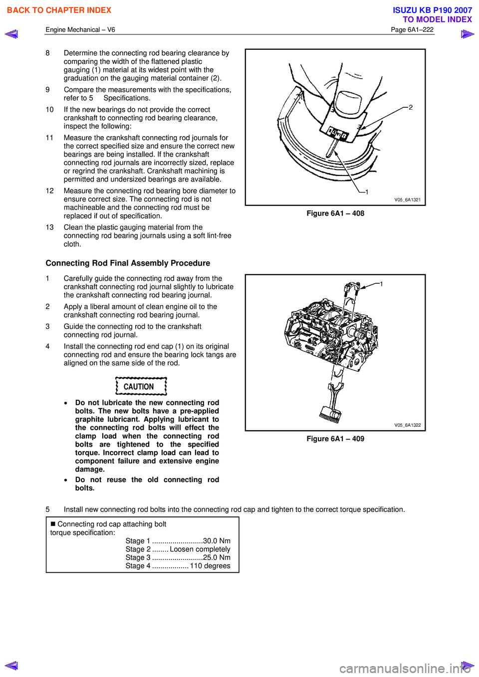
8 Determine the connecting rod bearing clearance by
comparing the width of the flattened plastic
gauging (1) material at its widest point with the
graduation on the gauging material container (2).
9 Compare the measurements with the specifications, refer to 5 Specifications.
10 If the new bearings do not provide the correct crankshaft to connecting rod bearing clearance,
inspect the following:
11 Measure the crankshaft connecting rod journals for the correct specified size and ensure the correct new
bearings are being installed. If the crankshaft
connecting rod journals are incorrectly sized, replace
or regrind the crankshaft. Crankshaft machining is
permitted and undersized bearings are available.
12 Measure the connecting rod bearing bore diameter to ensure correct size. The connecting rod is not
machineable and the connecting rod must be
replaced if out of specification.
13 Clean the plastic gauging material from the connecting rod bearing journals using a soft lint-free
cloth.
Figure 6A1 – 408
Connecting Rod Final Assembly Procedure
1 Carefully guide the connecting rod away from the crankshaft connecting rod journal slightly to lubricate
the crankshaft connecting rod bearing journal.
2 Apply a liberal amount of clean engine oil to the crankshaft connecting rod bearing journal.
3 Guide the connecting rod to the crankshaft connecting rod journal.
4 Install the connecting rod end cap (1) on its original connecting rod and ensure the bearing lock tangs are
aligned on the same side of the rod.
CAUTION
• Do not lubricate the new connecting rod
bolts. The new bolts have a pre-applied
graphite lubricant. Applying lubricant to
the connecting rod bolts will effect the
clamp load when the connecting rod
bolts are tightened to the specified
torque. Incorrect clamp load can lead to
component failure and extensive engine
damage.
• Do not reuse the old connecting rod
bolts.
Figure 6A1 – 409
5 Install new connecting rod bolts into the connecting rod cap and tighten to the correct torque specification. �„ Connecting rod cap attaching bolt
torque specification:
Stage 1 .........................30.0 Nm
Stage 2 ........ Loosen completely
Stage 3 .........................25.0 Nm
Stage 4 .................. 110 degrees
BACK TO CHAPTER INDEX
TO MODEL INDEX
ISUZU KB P190 2007
Page 2702 of 6020
Engine Mechanical – V6 Page 6A1–223
NOTE
During and after installation, ensure each piston
is positioned correctly in the correct cylinder. The
locating arrow on the top of each piston must be
pointing toward the front of the engine.
6 Repeat these procedures for the remaining piston/connecting rod assemblies.
7 Reinstall the oil pan and oil pump pick up assembly, refer to 4.2 Oil Pan and Oil Pump Suction Pipe Assembly.
8 Reinstall the cylinder heads, refer to 3.22 Cylinder Head Assembly.
9 Reinstall the engine assembly, refer to 4.1 Engine .
4.6 Crankshaft and Main Bearings
1 Remove the engine assembly, refer to 4.1 Engine .
2 Remove both cylinder head assemblies, refer to 3.22 Cylinder Head Assembly.
3 Remove the oil pan assembly, refer to 4.2 Oil Pan and Oil Pump Suction Pipe Assembly.
4 Remove the piston and connecting rod assemblies, refer to 4.5 Pistons, Pins, Rings, Connecting Rods and Big- end Bearings.
5 Remove the oil pump assembly, refer to 3.17 Oil Pump Assembly.
6 Remove the crankshaft rear oil seal and plate assembly, refer to 4.4 Crankshaft Rear Seal and Plate Assembly.
7 Remove the crankshaft position sensor, refer to 6C1-3 Engine Management – V6 – Service Operations.
Crankshaft End Play Measurement
1 Place a dial indicator at the end of the crankshaft nose.
2 Gently force the crankshaft towards the front and rear of the cylinder block with a lever while monitoring the movement of the dial indicator.
3 The crankshaft endplay should not exceed specifications, refer to 5 Specifications.
4 If the specifications are exceeded, inspect the thrust bearing thrust outer diameter and the crankshaft thrust wall for wear and/or excessive runout. Compare the values with the specifications, refer to 5 Specifications.
5 Replace the thrust bearing or crankshaft as required.
Remove
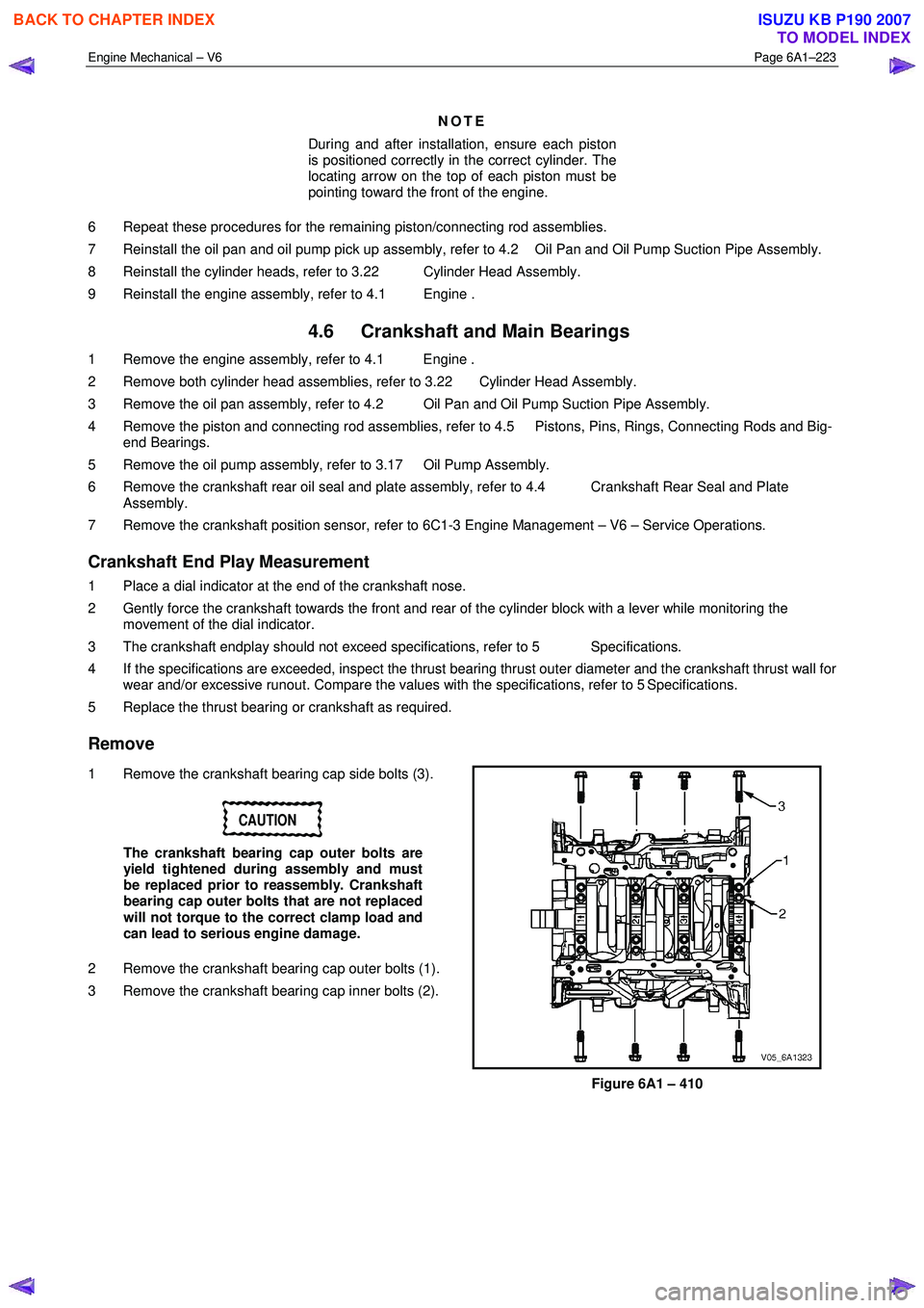
1 Remove the crankshaft bearing cap side bolts (3).
CAUTION
The crankshaft bearing cap outer bolts are
yield tightened during assembly and must
be replaced prior to reassembly. Crankshaft
bearing cap outer bolts that are not replaced
will not torque to the correct clamp load and
can lead to serious engine damage.
2 Remove the crankshaft bearing cap outer bolts (1).
3 Remove the crankshaft bearing cap inner bolts (2).
Figure 6A1 – 410
BACK TO CHAPTER INDEX
TO MODEL INDEX
ISUZU KB P190 2007
Page 2703 of 6020
Engine Mechanical – V6 Page 6A1–224
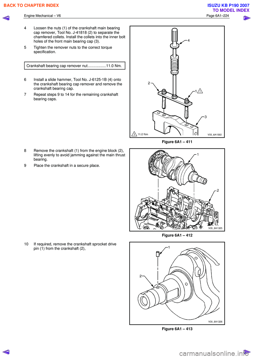
4 Loosen the nuts (1) of the crankshaft main bearing
cap remover, Tool No. J-41818 (2) to separate the
chamfered collets. Install the collets into the inner bolt
holes of the front main bearing cap (3).
5 Tighten the remover nuts to the correct torque specification.
Crankshaft bearing cap remover nut .................11.0 Nm.
6 Install a slide hammer, Tool No. J-6125-1B (4) onto the crankshaft bearing cap remover and remove the
crankshaft bearing cap.
7 Repeat steps 9 to 14 for the remaining crankshaft bearing caps.
Figure 6A1 – 411
8 Remove the crankshaft (1) from the engine block (2), lifting evenly to avoid jamming against the main thrust
bearing.
9 Place the crankshaft in a secure place.
Figure 6A1 – 412
10 If required, remove the crankshaft sprocket drive pin (1) from the crankshaft (2),
Figure 6A1 – 413
BACK TO CHAPTER INDEX
TO MODEL INDEX
ISUZU KB P190 2007
Page 2704 of 6020
Engine Mechanical – V6 Page 6A1–225
Crankshaft Bearing
1 Prepare a piece of cardboard or similar, numbered 1
– 4 for bearing identification.
NOTE
Main bearing journals are numbered from the
front of the engine.
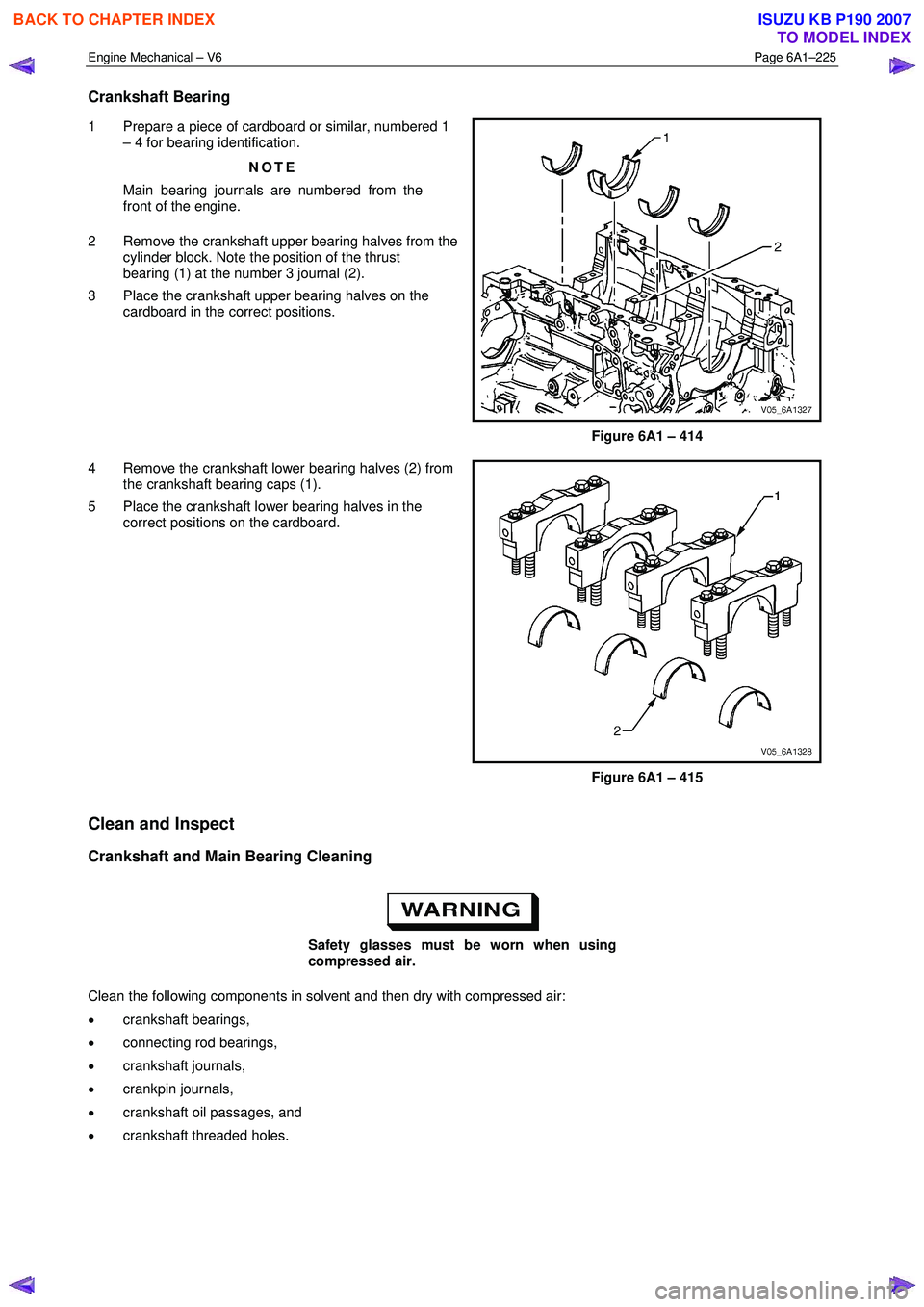
2 Remove the crankshaft upper bearing halves from the cylinder block. Note the position of the thrust
bearing (1) at the number 3 journal (2).
3 Place the crankshaft upper bearing halves on the cardboard in the correct positions.
Figure 6A1 – 414
4 Remove the crankshaft lower bearing halves (2) from the crankshaft bearing caps (1).
5 Place the crankshaft lower bearing halves in the correct positions on the cardboard.
Figure 6A1 – 415
Clean and Inspect
Crankshaft and Main Bearing Cleaning
Safety glasses must be worn when using
compressed air.
Clean the following components in solvent and then dry with compressed air:
• crankshaft bearings,
• connecting rod bearings,
• crankshaft journals,
• crankpin journals,
• crankshaft oil passages, and
• crankshaft threaded holes.
BACK TO CHAPTER INDEX
TO MODEL INDEX
ISUZU KB P190 2007
Page 2705 of 6020
Engine Mechanical – V6 Page 6A1–226
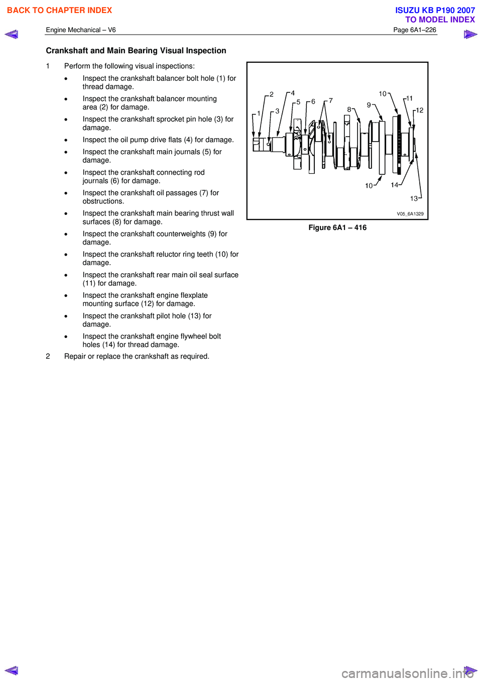
Crankshaft and Main Bearing Visual Inspection
1 Perform the following visual inspections:
• Inspect the crankshaft balancer bolt hole (1) for
thread damage.
• Inspect the crankshaft balancer mounting
area (2) for damage.
• Inspect the crankshaft sprocket pin hole (3) for
damage.
• Inspect the oil pump drive flats (4) for damage.
• Inspect the crankshaft main journals (5) for
damage.
• Inspect the crankshaft connecting rod
journals (6) for damage.
• Inspect the crankshaft oil passages (7) for
obstructions.
• Inspect the crankshaft main bearing thrust wall
surfaces (8) for damage.
• Inspect the crankshaft counterweights (9) for
damage.
• Inspect the crankshaft reluctor ring teeth (10) for
damage.
• Inspect the crankshaft rear main oil seal surface
(11) for damage.
• Inspect the crankshaft engine flexplate
mounting surface (12) for damage.
• Inspect the crankshaft pilot hole (13) for
damage.
• Inspect the crankshaft engine flywheel bolt
holes (14) for thread damage.
2 Repair or replace the crankshaft as required.
Figure 6A1 – 416
BACK TO CHAPTER INDEX
TO MODEL INDEX
ISUZU KB P190 2007
Page 2706 of 6020
Engine Mechanical – V6 Page 6A1–227
Crankshaft Main Bearing Inspection
CAUTION
All connecting rod and main journal bearings
that have been used in a running engine must
be replaced. Never re-use the crankshaft or
connecting rod bearings.
NOTE
The following bearing wear conditions should be
used to diagnose engine operating conditions or
root cause of a condition.
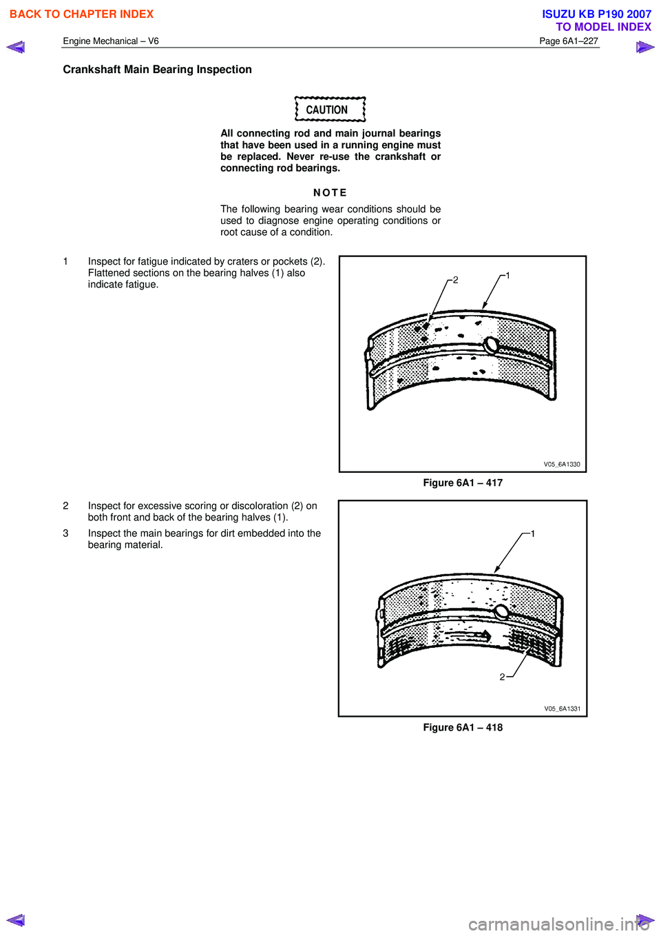
1 Inspect for fatigue indicated by craters or pockets (2). Flattened sections on the bearing halves (1) also
indicate fatigue.
Figure 6A1 – 417
2 Inspect for excessive scoring or discoloration (2) on both front and back of the bearing halves (1).
3 Inspect the main bearings for dirt embedded into the bearing material.
Figure 6A1 – 418
BACK TO CHAPTER INDEX
TO MODEL INDEX
ISUZU KB P190 2007
Page 2707 of 6020
Engine Mechanical – V6 Page 6A1–228
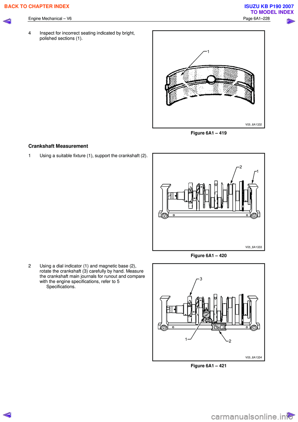
4 Inspect for incorrect seating indicated by bright,
polished sections (1).
Figure 6A1 – 419
Crankshaft Measurement
1 Using a suitable fixture (1), support the crankshaft (2).
Figure 6A1 – 420
2 Using a dial indicator (1) and magnetic base (2), rotate the crankshaft (3) carefully by hand. Measure
the crankshaft main journals for runout and compare
with the engine specifications, refer to 5
Specifications.
Figure 6A1 – 421
BACK TO CHAPTER INDEX
TO MODEL INDEX
ISUZU KB P190 2007
Page 2708 of 6020
Engine Mechanical – V6 Page 6A1–229
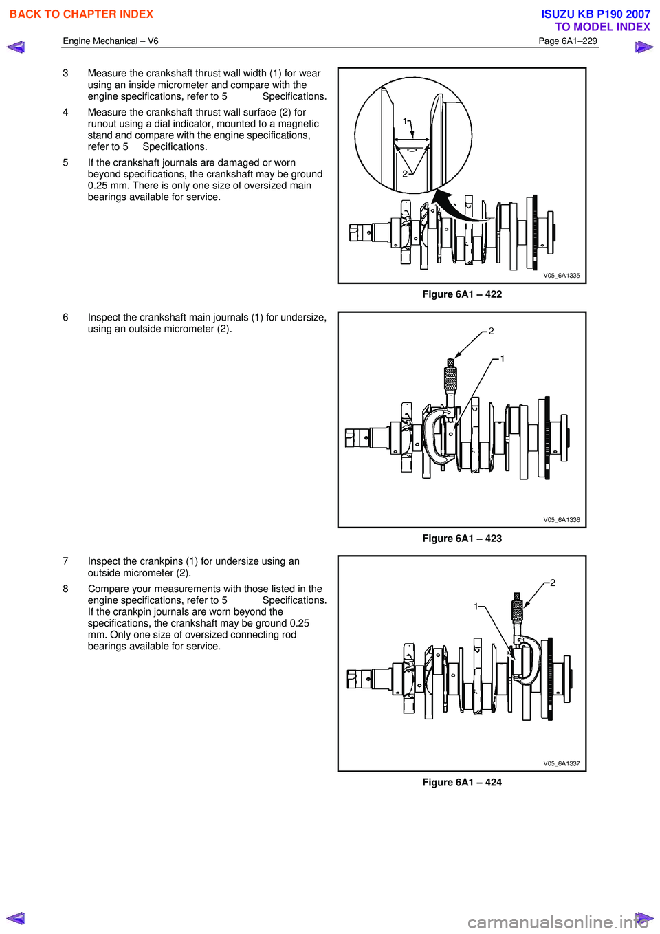
3 Measure the crankshaft thrust wall width (1) for wear
using an inside micrometer and compare with the
engine specifications, refer to 5 Specifications.
4 Measure the crankshaft thrust wall surface (2) for runout using a dial indicator, mounted to a magnetic
stand and compare with the engine specifications,
refer to 5 Specifications.
5 If the crankshaft journals are damaged or worn beyond specifications, the crankshaft may be ground
0.25 mm. There is only one size of oversized main
bearings available for service.
Figure 6A1 – 422
6 Inspect the crankshaft main journals (1) for undersize, using an outside micrometer (2).
Figure 6A1 – 423
7 Inspect the crankpins (1) for undersize using an outside micrometer (2).
8 Compare your measurements with those listed in the engine specifications, refer to 5 Specifications.
If the crankpin journals are worn beyond the
specifications, the crankshaft may be ground 0.25
mm. Only one size of oversized connecting rod
bearings available for service.
Figure 6A1 – 424
BACK TO CHAPTER INDEX
TO MODEL INDEX
ISUZU KB P190 2007
Page 2709 of 6020
Engine Mechanical – V6 Page 6A1–230
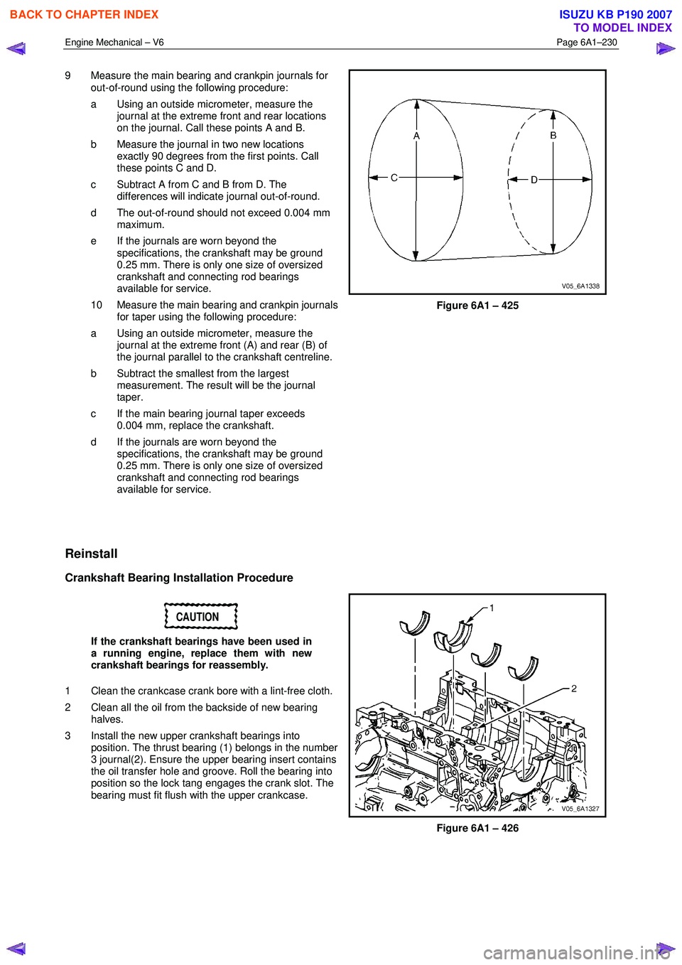
9 Measure the main bearing and crankpin journals for
out-of-round using the following procedure:
a Using an outside micrometer, measure the journal at the extreme front and rear locations
on the journal. Call these points A and B.
b Measure the journal in two new locations exactly 90 degrees from the first points. Call
these points C and D.
c Subtract A from C and B from D. The differences will indicate journal out-of-round.
d The out-of-round should not exceed 0.004 mm maximum.
e If the journals are worn beyond the specifications, the crankshaft may be ground
0.25 mm. There is only one size of oversized
crankshaft and connecting rod bearings
available for service.
10 Measure the main bearing and crankpin journals for taper using the following procedure:
a Using an outside micrometer, measure the journal at the extreme front (A) and rear (B) of
the journal parallel to the crankshaft centreline.
b Subtract the smallest from the largest measurement. The result will be the journal
taper.
c If the main bearing journal taper exceeds 0.004 mm, replace the crankshaft.
d If the journals are worn beyond the specifications, the crankshaft may be ground
0.25 mm. There is only one size of oversized
crankshaft and connecting rod bearings
available for service.
Figure 6A1 – 425
Reinstall
Crankshaft Bearing Installation Procedure
CAUTION
If the crankshaft bearings have been used in
a running engine, replace them with new
crankshaft bearings for reassembly.
1 Clean the crankcase crank bore with a lint-free cloth.
2 Clean all the oil from the backside of new bearing halves.
3 Install the new upper crankshaft bearings into position. The thrust bearing (1) belongs in the number
3 journal(2). Ensure the upper bearing insert contains
the oil transfer hole and groove. Roll the bearing into
position so the lock tang engages the crank slot. The
bearing must fit flush with the upper crankcase.
Figure 6A1 – 426
BACK TO CHAPTER INDEX
TO MODEL INDEX
ISUZU KB P190 2007
Page 2710 of 6020
Engine Mechanical – V6 Page 6A1–231
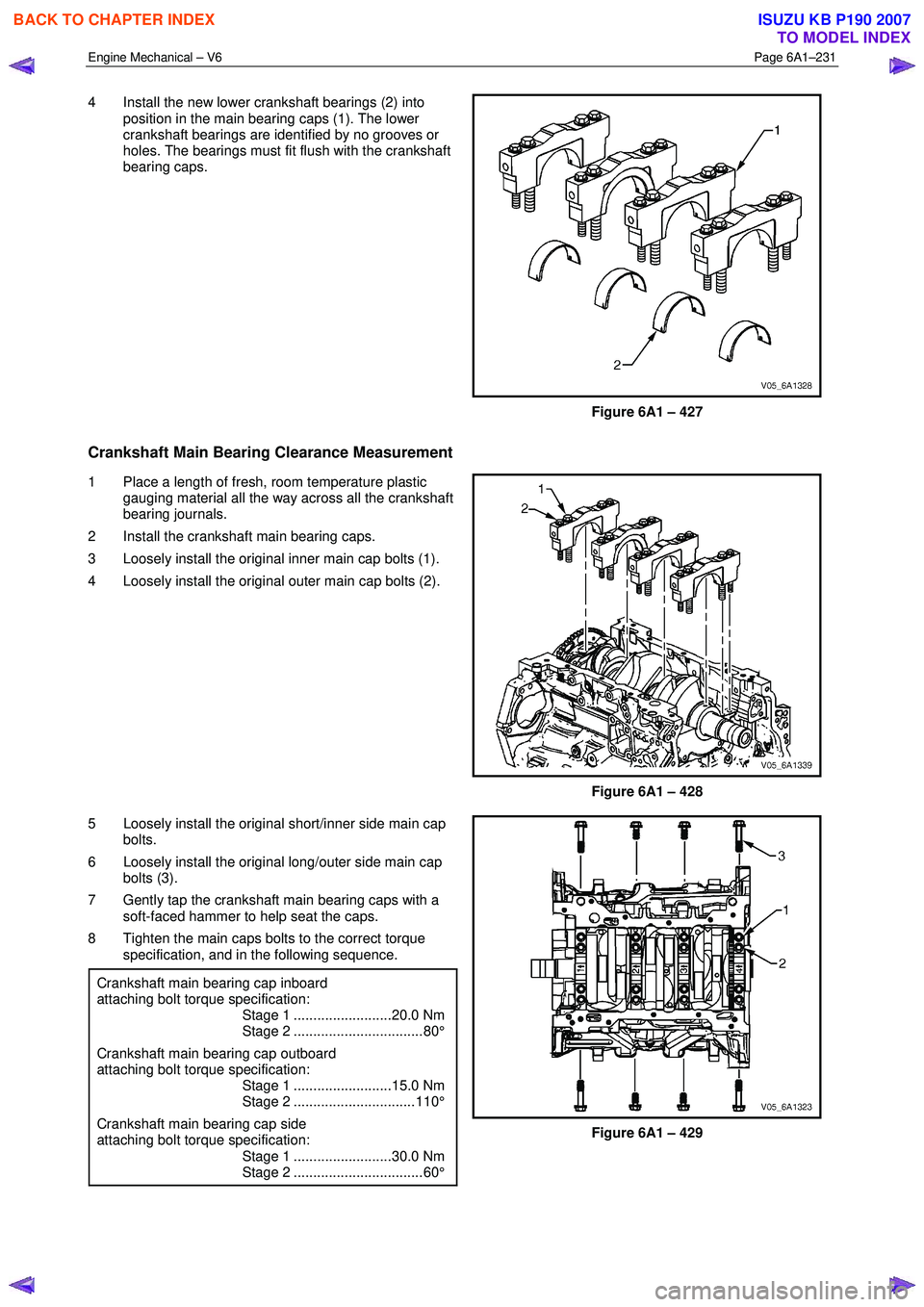
4 Install the new lower crankshaft bearings (2) into
position in the main bearing caps (1). The lower
crankshaft bearings are identified by no grooves or
holes. The bearings must fit flush with the crankshaft
bearing caps.
Figure 6A1 – 427
Crankshaft Main Bearing Clearance Measurement
1 Place a length of fresh, room temperature plastic gauging material all the way across all the crankshaft
bearing journals.
2 Install the crankshaft main bearing caps.
3 Loosely install the original inner main cap bolts (1).
4 Loosely install the original outer main cap bolts (2).
Figure 6A1 – 428
5 Loosely install the original short/inner side main cap bolts.
6 Loosely install the original long/outer side main cap bolts (3).
7 Gently tap the crankshaft main bearing caps with a soft-faced hammer to help seat the caps.
8 Tighten the main caps bolts to the correct torque specification, and in the following sequence.
Crankshaft main bearing cap inboard
attaching bolt torque specification:
Stage 1 .........................20.0 Nm
Stage 2 ................................. 80°
Crankshaft main bearing cap outboard
attaching bolt torque specification:
Stage 1 .........................15.0 Nm
Stage 2 ............................... 110°
Crankshaft main bearing cap side
attaching bolt torque specification:
Stage 1 .........................30.0 Nm
Stage 2 ................................. 60°
Figure 6A1 – 429
BACK TO CHAPTER INDEX
TO MODEL INDEX
ISUZU KB P190 2007