ISUZU KB P190 2007 Workshop Repair Manual
Manufacturer: ISUZU, Model Year: 2007, Model line: KB P190, Model: ISUZU KB P190 2007Pages: 6020, PDF Size: 70.23 MB
Page 2681 of 6020

Engine Mechanical – V6 Page 6A1–202
1 Install a new oil suction tube seal onto the oil suction
tube.
2 Install the oil suction pipe and tighten the attaching bolts to the correct torque specification.
Oil suction pipe attaching
bolt torque specification .....................................10.0 Nm
3 Install the crankshaft oil deflector into the oil pan assembly and tighten the attaching bolts to the
correct torque specification.
Crankshaft oil deflector
attaching bolt torque specification ......................10.0 Nm
4 Install the oil level sensor into the oil pan assembly and tighten to the correct torque specification.
Oil level sensor torque specification...................20.0 Nm
Figure 6A1 – 358
5 Install the oil pan drain plug into the oil pan assembly and tighten to the correct torque specification. Oil pan drain plug
torque specification ............................................25.0 Nm
Reinstall
1 Install the guide pins, Tool No. EN-46109 (1) into the oil pan rail bolt hole on each side of the engine block.
Figure 6A1 – 359
2 Place a 3mm bead (1) of RTV sealant on the cylinder block pan rail and crankshaft rear oil seal housing to
oil pan mating surfaces.
3 Position the oil pan onto the cylinder block.
4 Remove the guide pins, Tool No. EN-46109 from the cylinder block.
Figure 6A1 – 360
BACK TO CHAPTER INDEX
TO MODEL INDEX
ISUZU KB P190 2007
Page 2682 of 6020
Engine Mechanical – V6 Page 6A1–203
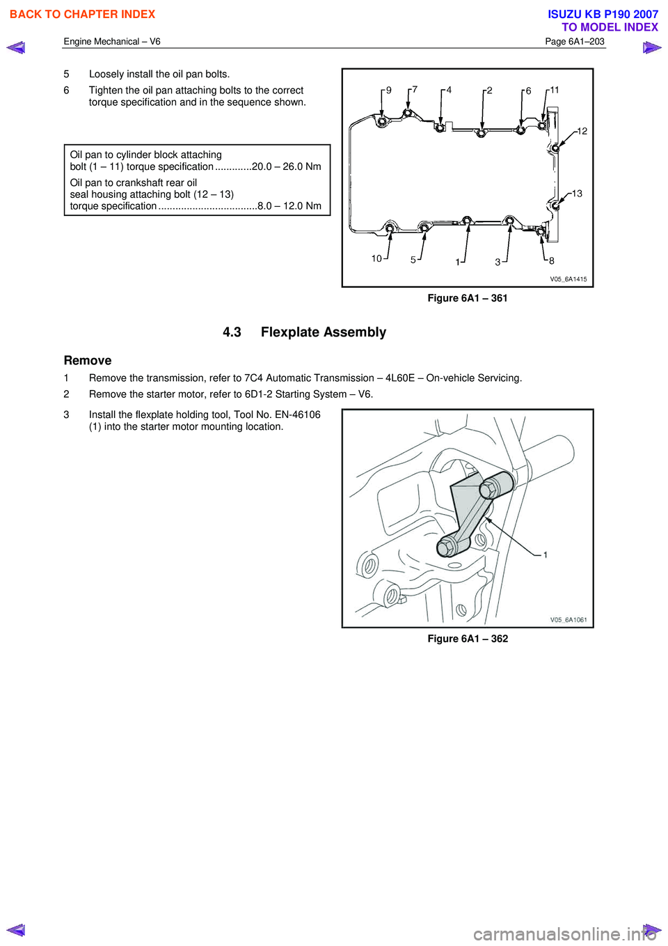
5 Loosely install the oil pan bolts.
6 Tighten the oil pan attaching bolts to the correct torque specification and in the sequence shown.
Oil pan to cylinder block attaching
bolt (1 – 11) torque specification .............20.0 – 26.0 Nm
Oil pan to crankshaft rear oil
seal housing attaching bolt (12 – 13)
torque specification ...................................8.0 – 12.0 Nm
Figure 6A1 – 361
4.3 Flexplate Assembly
Remove
1 Remove the transmission, refer to 7C4 Automatic Transmission – 4L60E – On-vehicle Servicing.
2 Remove the starter motor, refer to 6D1-2 Starting System – V6.
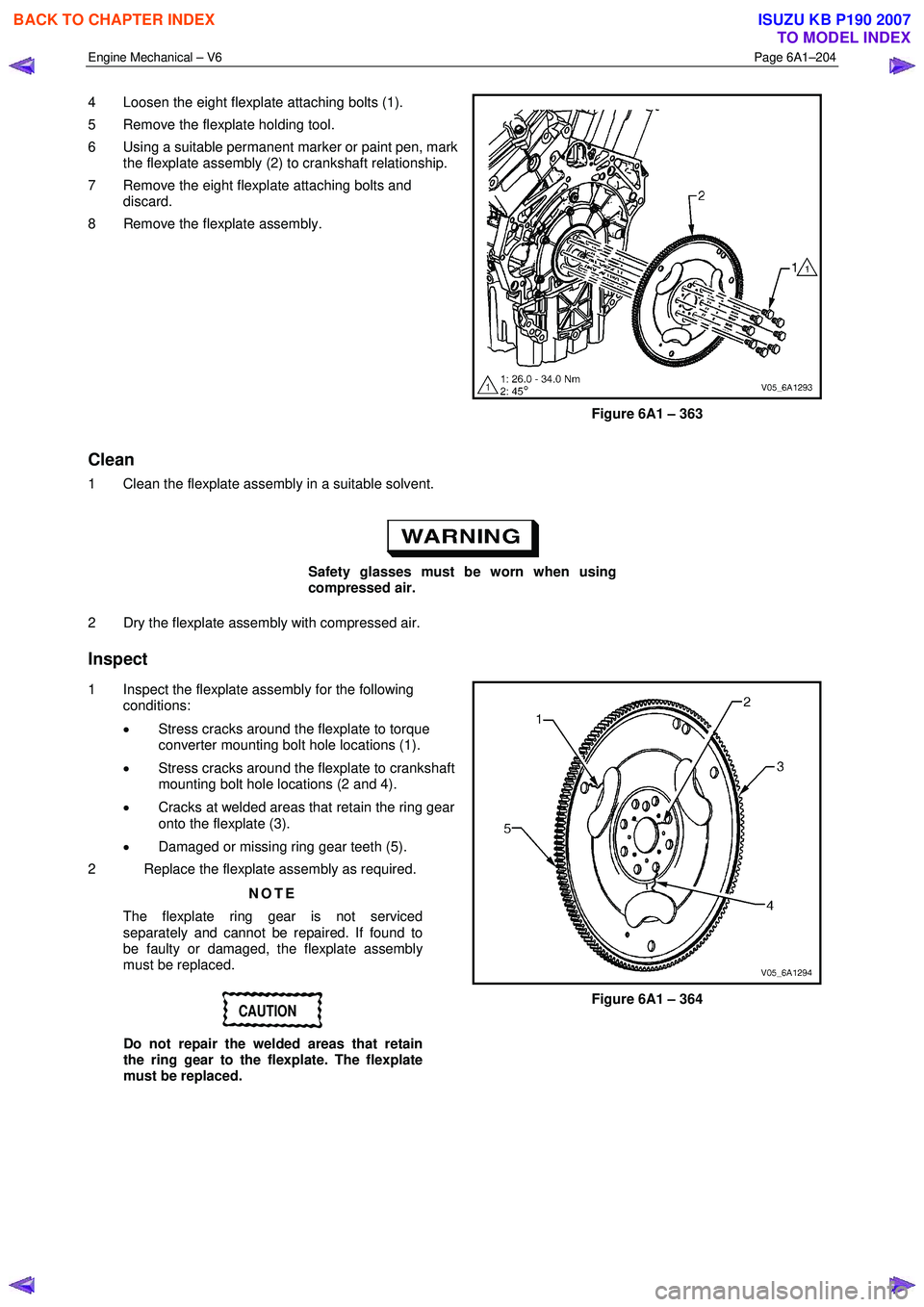
3 Install the flexplate holding tool, Tool No. EN-46106 (1) into the starter motor mounting location.
Figure 6A1 – 362
BACK TO CHAPTER INDEX
TO MODEL INDEX
ISUZU KB P190 2007
Page 2683 of 6020
Engine Mechanical – V6 Page 6A1–204
4 Loosen the eight flexplate attaching bolts (1).
5 Remove the flexplate holding tool.
6 Using a suitable permanent marker or paint pen, mark the flexplate assembly (2) to crankshaft relationship.
7 Remove the eight flexplate attaching bolts and discard.
8 Remove the flexplate assembly.
Figure 6A1 – 363
Clean
1 Clean the flexplate assembly in a suitable solvent.
Safety glasses must be worn when using
compressed air.
2 Dry the flexplate assembly with compressed air.
Inspect
1 Inspect the flexplate assembly for the following conditions:
• Stress cracks around the flexplate to torque
converter mounting bolt hole locations (1).
• Stress cracks around the flexplate to crankshaft
mounting bolt hole locations (2 and 4).
• Cracks at welded areas that retain the ring gear
onto the flexplate (3).
• Damaged or missing ring gear teeth (5).
2 Replace the flexplate assembly as required.
NOTE
The flexplate ring gear is not serviced
separately and cannot be repaired. If found to
be faulty or damaged, the flexplate assembly
must be replaced.
CAUTION
Do not repair the welded areas that retain
the ring gear to the flexplate. The flexplate
must be replaced.
Figure 6A1 – 364
BACK TO CHAPTER INDEX
TO MODEL INDEX
ISUZU KB P190 2007
Page 2684 of 6020
Engine Mechanical – V6 Page 6A1–205
Reinstall
NOTE
The bolt holes are unevenly spaced to enable
flexplate fitment in the one position only.
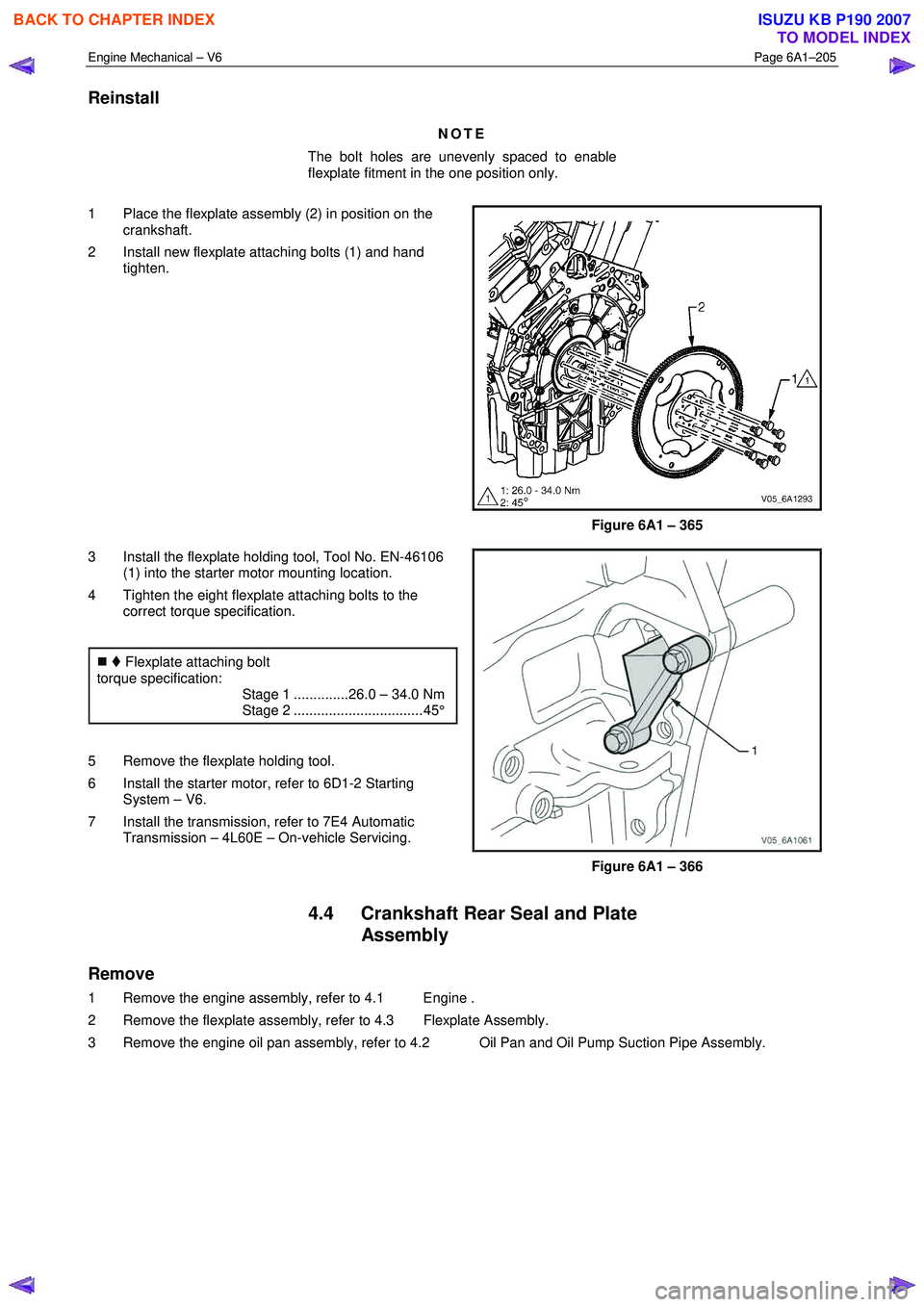
1 Place the flexplate assembly (2) in position on the crankshaft.
2 Install new flexplate attaching bolts (1) and hand tighten.
Figure 6A1 – 365
3 Install the flexplate holding tool, Tool No. EN-46106 (1) into the starter motor mounting location.
4 Tighten the eight flexplate attaching bolts to the correct torque specification.
�„ Flexplate attaching bolt
torque specification:
Stage 1 ..............26.0 – 34.0 Nm
Stage 2 ................................. 45°
5 Remove the flexplate holding tool.
6 Install the starter motor, refer to 6D1-2 Starting System – V6.
7 Install the transmission, refer to 7E4 Automatic Transmission – 4L60E – On-vehicle Servicing.
Figure 6A1 – 366
4.4 Crankshaft Rear Seal and Plate Assembly
Remove
1 Remove the engine assembly, refer to 4.1 Engine .
2 Remove the flexplate assembly, refer to 4.3 Flexplate Assembly.
3 Remove the engine oil pan assembly, refer to 4.2 Oil Pan and Oil Pump Suction Pipe Assembly.
BACK TO CHAPTER INDEX
TO MODEL INDEX
ISUZU KB P190 2007
Page 2685 of 6020
Engine Mechanical – V6 Page 6A1–206
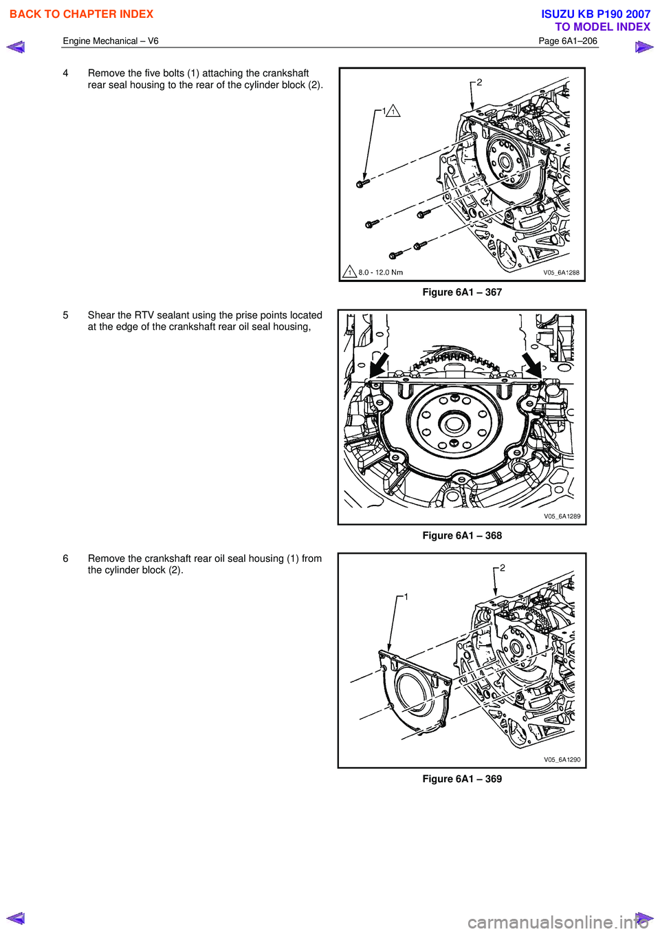
4 Remove the five bolts (1) attaching the crankshaft
rear seal housing to the rear of the cylinder block (2).
Figure 6A1 – 367
5 Shear the RTV sealant using the prise points located at the edge of the crankshaft rear oil seal housing,
Figure 6A1 – 368
6 Remove the crankshaft rear oil seal housing (1) from the cylinder block (2).
Figure 6A1 – 369
BACK TO CHAPTER INDEX
TO MODEL INDEX
ISUZU KB P190 2007
Page 2686 of 6020
Engine Mechanical – V6 Page 6A1–207
Reinstall
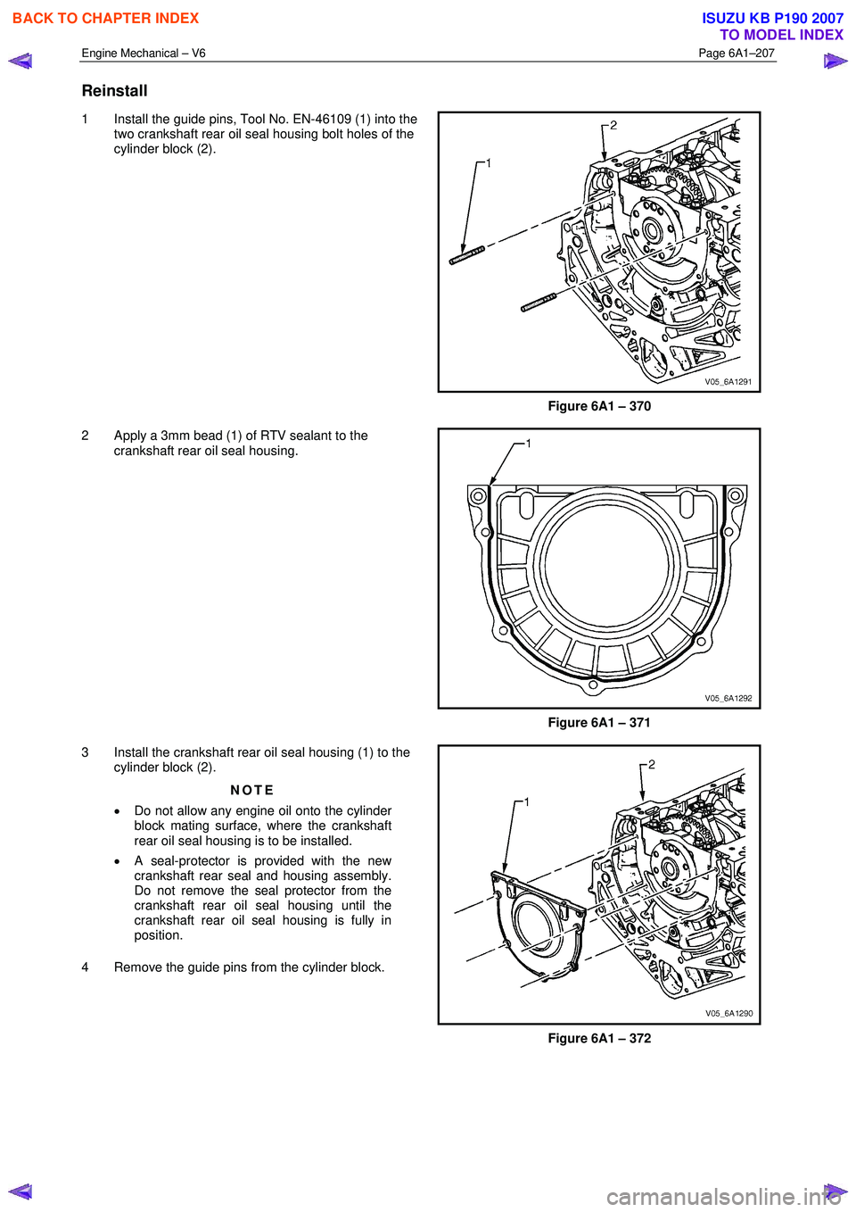
1 Install the guide pins, Tool No. EN-46109 (1) into the
two crankshaft rear oil seal housing bolt holes of the
cylinder block (2).
Figure 6A1 – 370
2 Apply a 3mm bead (1) of RTV sealant to the crankshaft rear oil seal housing.
Figure 6A1 – 371
3 Install the crankshaft rear oil seal housing (1) to the cylinder block (2).
NOTE
• Do not allow any engine oil onto the cylinder
block mating surface, where the crankshaft
rear oil seal housing is to be installed.
• A seal-protector is provided with the new
crankshaft rear seal and housing assembly.
Do not remove the seal protector from the
crankshaft rear oil seal housing until the
crankshaft rear oil seal housing is fully in
position.
4 Remove the guide pins from the cylinder block.
Figure 6A1 – 372
BACK TO CHAPTER INDEX
TO MODEL INDEX
ISUZU KB P190 2007
Page 2687 of 6020

Engine Mechanical – V6 Page 6A1–208
5 Install the crankshaft rear oil seal housing attaching
bolts (1) to the cylinder block (2) and tighten to the
correct torque specification.
Crankshaft rear oil seal housing
attaching bolt torque specification .............8.0 – 12.0 Nm
Figure 6A1 – 373
4.5 Pistons, Pins, Rings, Connecting Rods and Big-end Bearings
Remove
1 Remove the engine assembly, refer to 4.1 Engine .
2 Remove both cylinder head assemblies, refer to 3.22 Cylinder Head Assembly.
3 Remove the oil pan assembly, refer to 4.2 Oil Pan and Oil Pump Suction Pipe Assembly.
4 Mark the top of the piston being removed to identify its specific bore.
5 Install Tool No. EN-46111 (1) onto the crankshaft (2).
6 Rotate the crankshaft until the piston being removed is at the bottom of its stroke; bottom dead centre
(BDC).
Figure 6A1 – 374
CAUTION
If the connecting rod bearings have been
used in a running engine, they must be
replaced with new connecting rod bearings
for reassembly.
7 Before removing the connecting rods, check the connecting rod side clearance using the following procedure: a Tap the connecting rod to one end of the crankshaft journal with a dead blow or wooden hammer.
b Using feeler gauges, measure the clearance between the crankshaft counterweight and the connecting rod.
c The connecting rod side clearance should not exceed specifications, refer to 5 Specifications.
BACK TO CHAPTER INDEX
TO MODEL INDEX
ISUZU KB P190 2007
Page 2688 of 6020
Engine Mechanical – V6 Page 6A1–209
d If the endplay exceeds the specified limits, measure the width of the crankpin end of the connecting rod, refer
to 5 Specifications.
e If the connecting rod width is significantly smaller than specified and severe wear is present on the side of the connecting rod, replace the connecting rod.
f If the connecting rod width is within specification and excessive scoring is present on the crankshaft journals, replace the crankshaft.
CAUTION
Do not use a stamp, punch or any other
method that may distort or stress the
connecting rod and cap. Extensive engine
damage may result from a connecting rod that
is distorted or stressed.
8 Mark the cylinder number on the connecting rod and the connecting rod cap with a paint stick or permanent marker.
CAUTION
Powdered metal connecting rods have rod
bolts which yield when tighten to the
specified torque. If the bolts are loosened or
removed they must be replaced. Rod bolts
that are not replaced will not torque to the
correct clamp load and can lead to serious
engine damage.
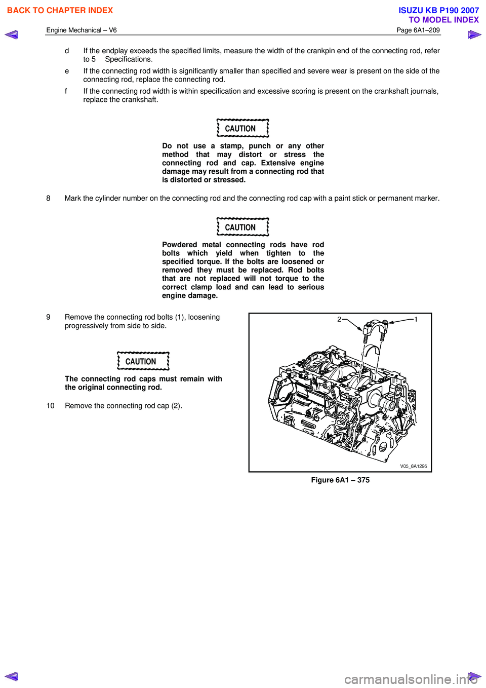
9 Remove the connecting rod bolts (1), loosening progressively from side to side.
CAUTION
The connecting rod caps must remain with
the original connecting rod.
10 Remove the connecting rod cap (2).
Figure 6A1 – 375
BACK TO CHAPTER INDEX
TO MODEL INDEX
ISUZU KB P190 2007
Page 2689 of 6020
Engine Mechanical – V6 Page 6A1–210
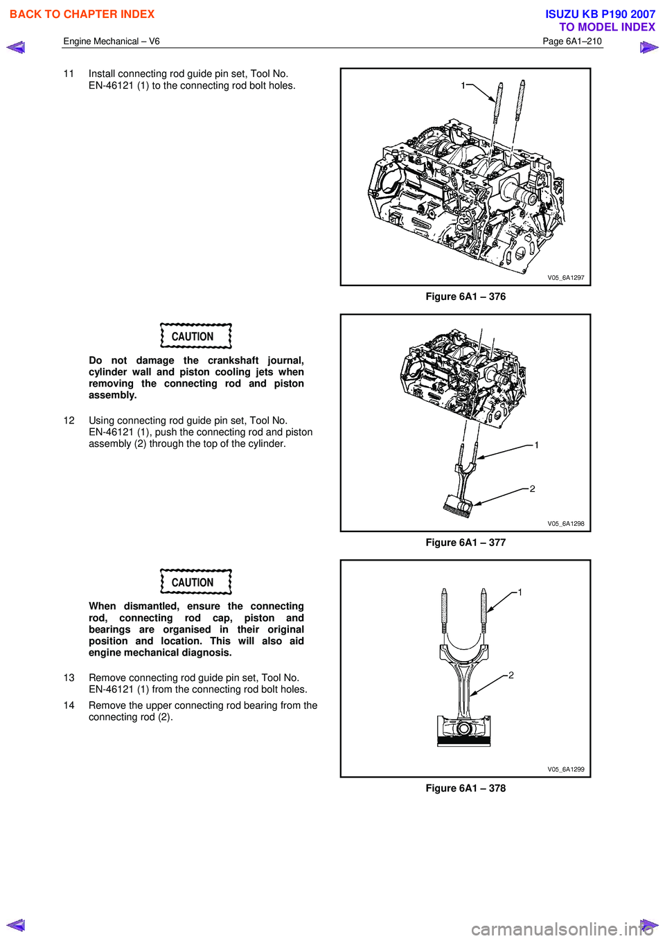
11 Install connecting rod guide pin set, Tool No.
EN-46121 (1) to the connecting rod bolt holes.
Figure 6A1 – 376
CAUTION
Do not damage the crankshaft journal,
cylinder wall and piston cooling jets when
removing the connecting rod and piston
assembly.
12 Using connecting rod guide pin set, Tool No. EN-46121 (1), push the connecting rod and piston
assembly (2) through the top of the cylinder.
Figure 6A1 – 377
CAUTION
When dismantled, ensure the connecting
rod, connecting rod cap, piston and
bearings are organised in their original
position and location. This will also aid
engine mechanical diagnosis.
13 Remove connecting rod guide pin set, Tool No. EN-46121 (1) from the connecting rod bolt holes.
14 Remove the upper connecting rod bearing from the connecting rod (2).
Figure 6A1 – 378
BACK TO CHAPTER INDEX
TO MODEL INDEX
ISUZU KB P190 2007
Page 2690 of 6020
Engine Mechanical – V6 Page 6A1–211
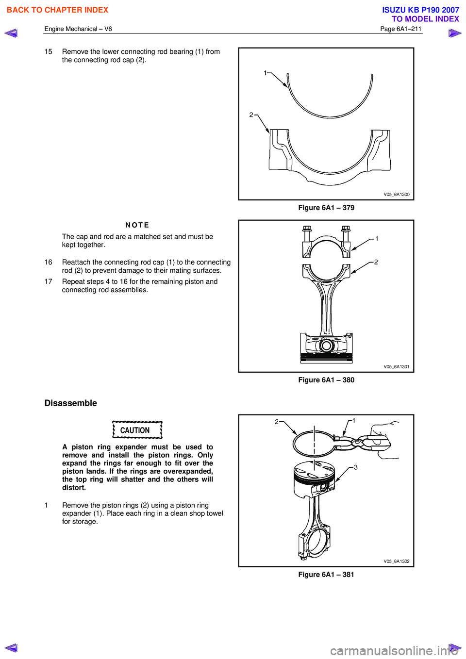
15 Remove the lower connecting rod bearing (1) from
the connecting rod cap (2).
Figure 6A1 – 379
NOTE
The cap and rod are a matched set and must be
kept together.
16 Reattach the connecting rod cap (1) to the connecting rod (2) to prevent damage to their mating surfaces.
17 Repeat steps 4 to 16 for the remaining piston and connecting rod assemblies.
Figure 6A1 – 380
Disassemble
CAUTION
A piston ring expander must be used to
remove and install the piston rings. Only
expand the rings far enough to fit over the
piston lands. If the rings are overexpanded,
the top ring will shatter and the others will
distort.
1 Remove the piston rings (2) using a piston ring expander (1). Place each ring in a clean shop towel
for storage.
Figure 6A1 – 381
BACK TO CHAPTER INDEX
TO MODEL INDEX
ISUZU KB P190 2007