ISUZU KB P190 2007 Workshop Repair Manual
KB P190 2007
ISUZU
ISUZU
https://www.carmanualsonline.info/img/61/57177/w960_57177-0.png
ISUZU KB P190 2007 Workshop Repair Manual
Trending: fuel tank capacity, spark plugs, tyre pressure, ignition, weight, tires, instrument panel
Page 2891 of 6020
Engine Mechanical – V6 Page 6A1–114
Page 6A1–114
Remove
Right-hand Secondary Timing Chain
CAUTION
After removing the upper intake manifold, and
spark plugs, plug any openings to prevent dirt
and other contaminants from entering.
1 Remove the engine front cover assembly, refer to 3.15 Front Cover Assembly.
2 Remove the spark plugs to aid crankshaft/engine rotation, refer to Section 6C1-3 Engine Management – V6 –
Service Operations .
3 Install Tool No. EN46111 (1) onto the crankshaft (2).
Figure 6A1 – 103
4 Using Tool No. EN46111 (1), rotate the crankshaft in a clockwise direction until the crankshaft sprocket
timing mark (2) is aligned with the indexing mark (3)
on the oil pump housing.
NOTE
Graphic shows 'Early Type' crankshaft sprocket,
'Late Type' similar.
Figure 6A1 – 104
BACK TO CHAPTER INDEX
TO MODEL INDEX
ISUZU KB P190 2007
Page 2892 of 6020
Engine Mechanical – V6 Page 6A1–115
Page 6A1–115
5 After aligning the crankshaft sprocket timing mark,
check that the camshaft flats (1) at the rear of the
right-hand cylinder head are parallel with the
camshaft cover rail (2).
6 If the camshaft flats are not as shown, rotate the crankshaft 360 °.
Figure 6A1 – 105
7 Install Tool No. EN 46105–1 (1) onto the rear of the right-hand cylinder head camshafts (2).
Figure 6A1 – 106
8 Install Tool No. EN 46105–2 (1) onto the rear of the left-hand cylinder head camshafts (2).
Figure 6A1 – 107
BACK TO CHAPTER INDEX
TO MODEL INDEX
ISUZU KB P190 2007
Page 2893 of 6020
Engine Mechanical – V6 Page 6A1–116
Page 6A1–116
9 Remove the right-hand secondary timing chain
tensioner bolts (1) and remove the tensioner (2).
NOTE
Take care when removing the tensioner bolts.
The tensioner plunger is subjected to spring
tension and may spring apart during tensioner
removal.
Figure 6A1 – 108
10 Remove the tensioner gaske t (1) from the tensioner
(2) and discard the gasket.
11 Inspect the tensioner m ounting surface on the right-
hand cylinder head for burrs or any defects that would
affect the sealing of a new tensioner gasket.
Figure 6A1 – 109
12 Remove the right-hand secondary timing chain shoe bolt (1).
Figure 6A1 – 110
BACK TO CHAPTER INDEX
TO MODEL INDEX
ISUZU KB P190 2007
Page 2894 of 6020
Engine Mechanical – V6 Page 6A1–117
Page 6A1–117
13 Remove the right-hand secondary timing chain shoe
(1).
Figure 6A1 – 111
14 Remove the two right-hand secondary timing chain guide bolts (1) and remove the guide (2).
Figure 6A1 – 112
15 Remove the right-hand secondary timing chain (1) from the camshaft positi on actuators (2) and the
camshaft intermediate sprocket (3).
Figure 6A1 – 113
BACK TO CHAPTER INDEX
TO MODEL INDEX
ISUZU KB P190 2007
Page 2895 of 6020
Engine Mechanical – V6 Page 6A1–118
Page 6A1–118
Primary Timing Chain
1 Remove the right-hand secondary timing chain, refer to Right-hand Secondary Timing Chain in this Section.
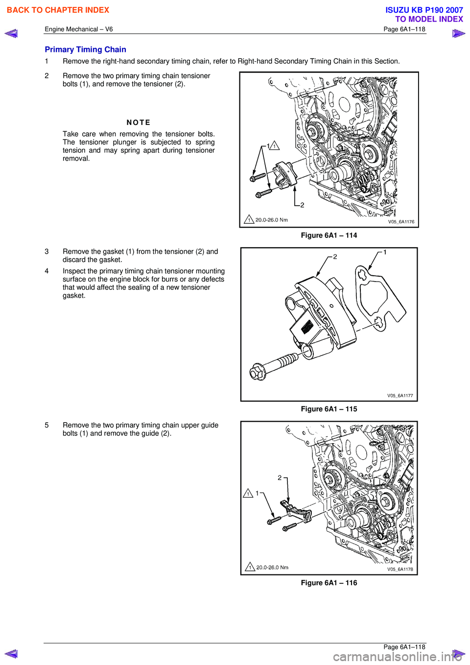
2 Remove the two primary timing chain tensioner bolts (1), and remove the tensioner (2).
NOTE
Take care when removing the tensioner bolts.
The tensioner plunger is subjected to spring
tension and may spring apart during tensioner
removal.
Figure 6A1 – 114
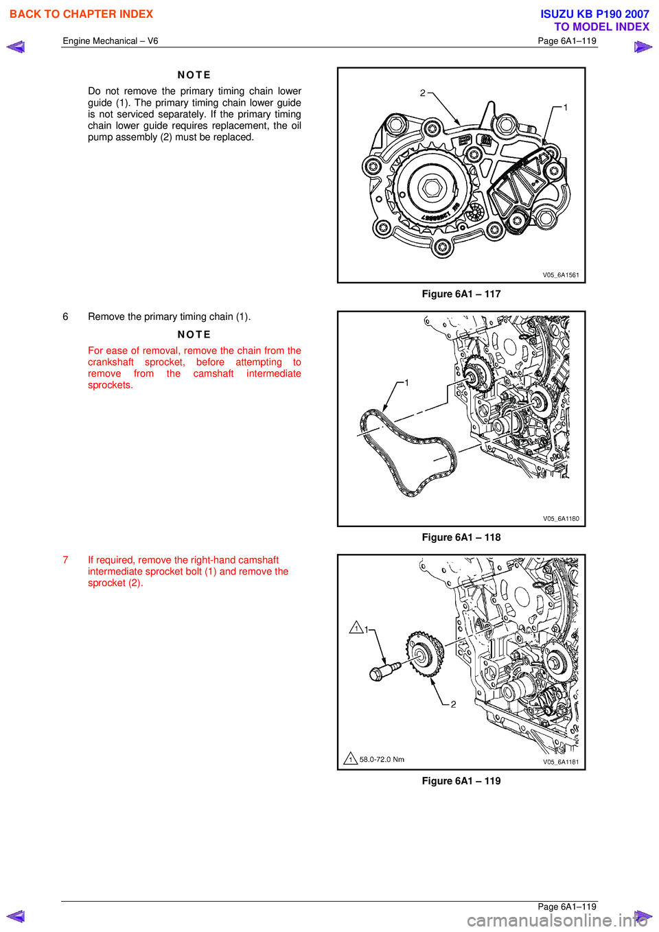
3 Remove the gasket (1) from the tensioner (2) and discard the gasket.
4 Inspect the primary timi ng chain tensioner mounting
surface on the engine block for burrs or any defects
that would affect the s ealing of a new tensioner
gasket.
Figure 6A1 – 115
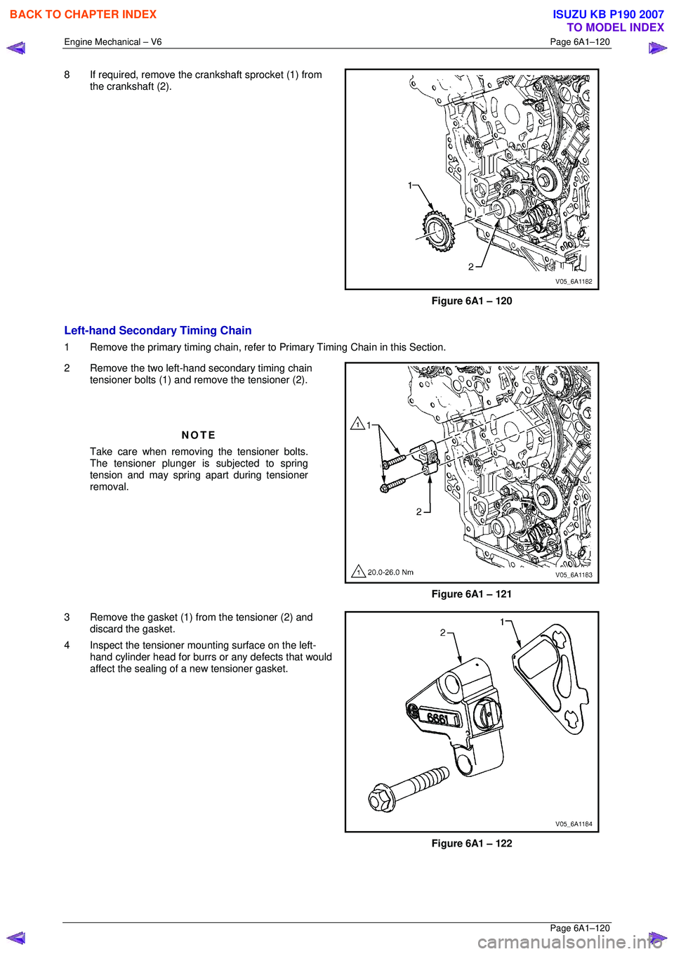
5 Remove the two primary timing chain upper guide bolts (1) and remove the guide (2).
Figure 6A1 – 116
BACK TO CHAPTER INDEX
TO MODEL INDEX
ISUZU KB P190 2007
Page 2896 of 6020
Engine Mechanical – V6 Page 6A1–119
Page 6A1–119
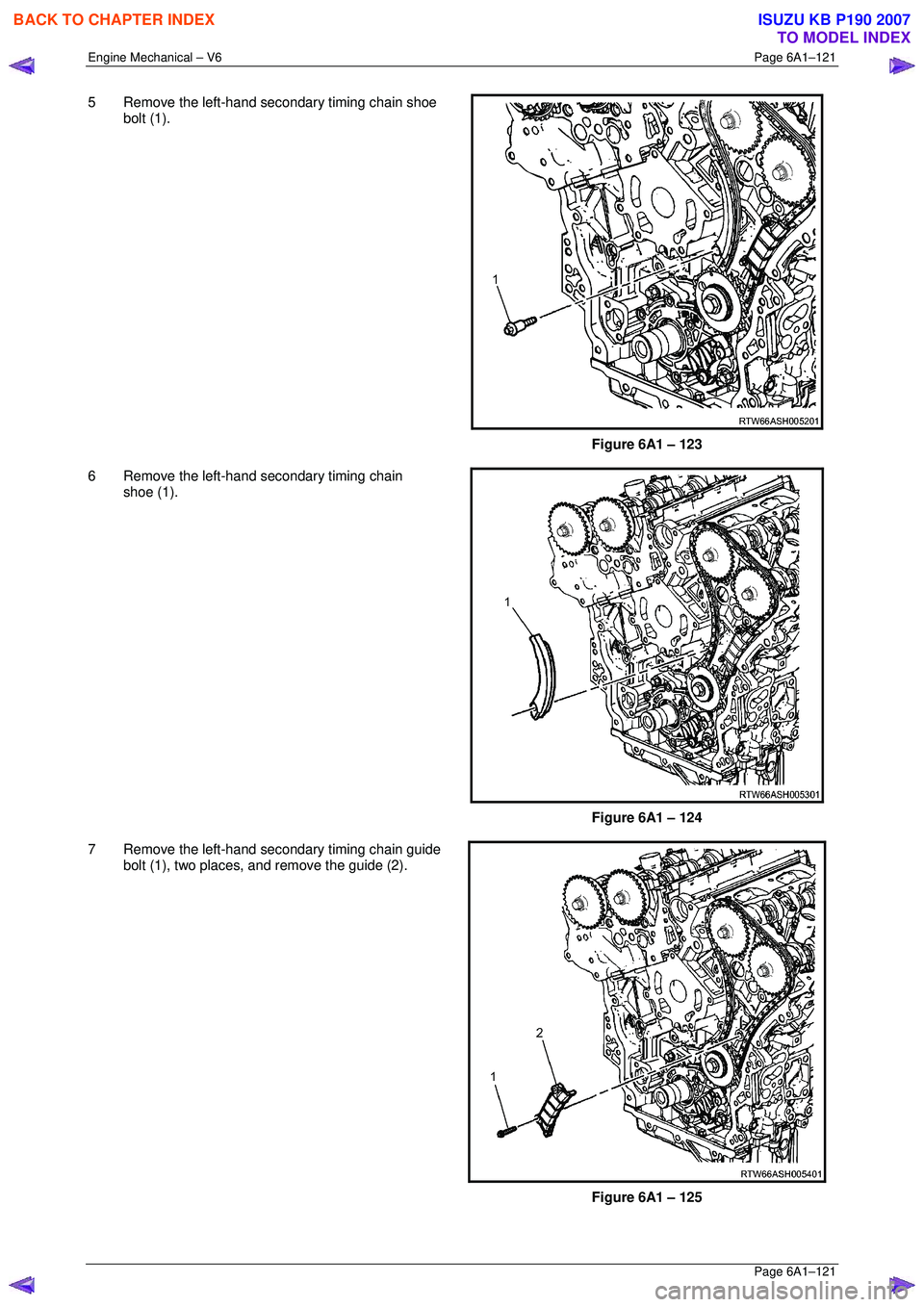
NOTE
Do not remove the primary timing chain lower
guide (1). The primary timing chain lower guide
is not serviced separately. If the primary timing
chain lower guide requires replacement, the oil
pump assembly (2) must be replaced.
Figure 6A1 – 117
6 Remove the primary timing chain (1). NOTE
For ease of removal, remove the chain from the
crankshaft sprocket, bef ore attempting to
remove from the camshaft intermediate
sprockets.
Figure 6A1 – 118
7 If required, remove the right-hand camshaft intermediate sprocket bolt (1) and remove the
sprocket (2).
Figure 6A1 – 119
BACK TO CHAPTER INDEX
TO MODEL INDEX
ISUZU KB P190 2007
Page 2897 of 6020
Engine Mechanical – V6 Page 6A1–120
Page 6A1–120
8 If required, remove the crankshaft sprocket (1) from
the crankshaft (2).
Figure 6A1 – 120
Left-hand Secondary Timing Chain
1 Remove the primary timing chain, refer to Primary Timing Chain in this Section.
2 Remove the two left-hand secondary timing chain tensioner bolts (1) and remove the tensioner (2).
NOTE
Take care when removing the tensioner bolts.
The tensioner plunger is subjected to spring
tension and may spring apart during tensioner
removal.
Figure 6A1 – 121
3 Remove the gasket (1) from the tensioner (2) and discard the gasket.
4 Inspect the tensioner m ounting surface on the left-
hand cylinder head for burrs or any defects that would
affect the sealing of a new tensioner gasket.
Figure 6A1 – 122
BACK TO CHAPTER INDEX
TO MODEL INDEX
ISUZU KB P190 2007
Page 2898 of 6020
Engine Mechanical – V6 Page 6A1–121
Page 6A1–121
5 Remove the left-hand secondary timing chain shoe
bolt (1).
Figure 6A1 – 123
6 Remove the left-hand secondary timing chain shoe (1).
Figure 6A1 – 124
7 Remove the left-hand secondary timing chain guide bolt (1), two places, and remove the guide (2).
Figure 6A1 – 125
BACK TO CHAPTER INDEX
TO MODEL INDEX
ISUZU KB P190 2007
Page 2899 of 6020
Engine Mechanical – V6 Page 6A1–122
Page 6A1–122
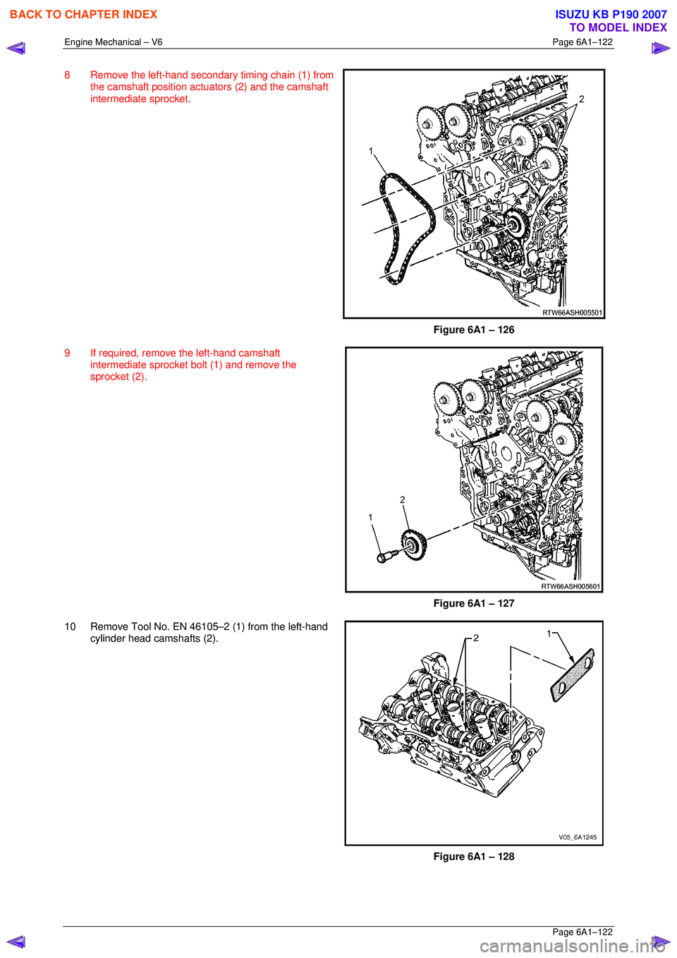
8 Remove the left-hand secondary timing chain (1) from
the camshaft position actuators (2) and the camshaft
intermediate sprocket.
Figure 6A1 – 126
9 If required, remove the left-hand camshaft intermediate sprocket bolt (1) and remove the
sprocket (2).
Figure 6A1 – 127
10 Remove Tool No. EN 46105–2 (1) from the left-hand cylinder head camshafts (2).
Figure 6A1 – 128
BACK TO CHAPTER INDEX
TO MODEL INDEX
ISUZU KB P190 2007
Page 2900 of 6020
Engine Mechanical – V6 Page 6A1–123
Page 6A1–123
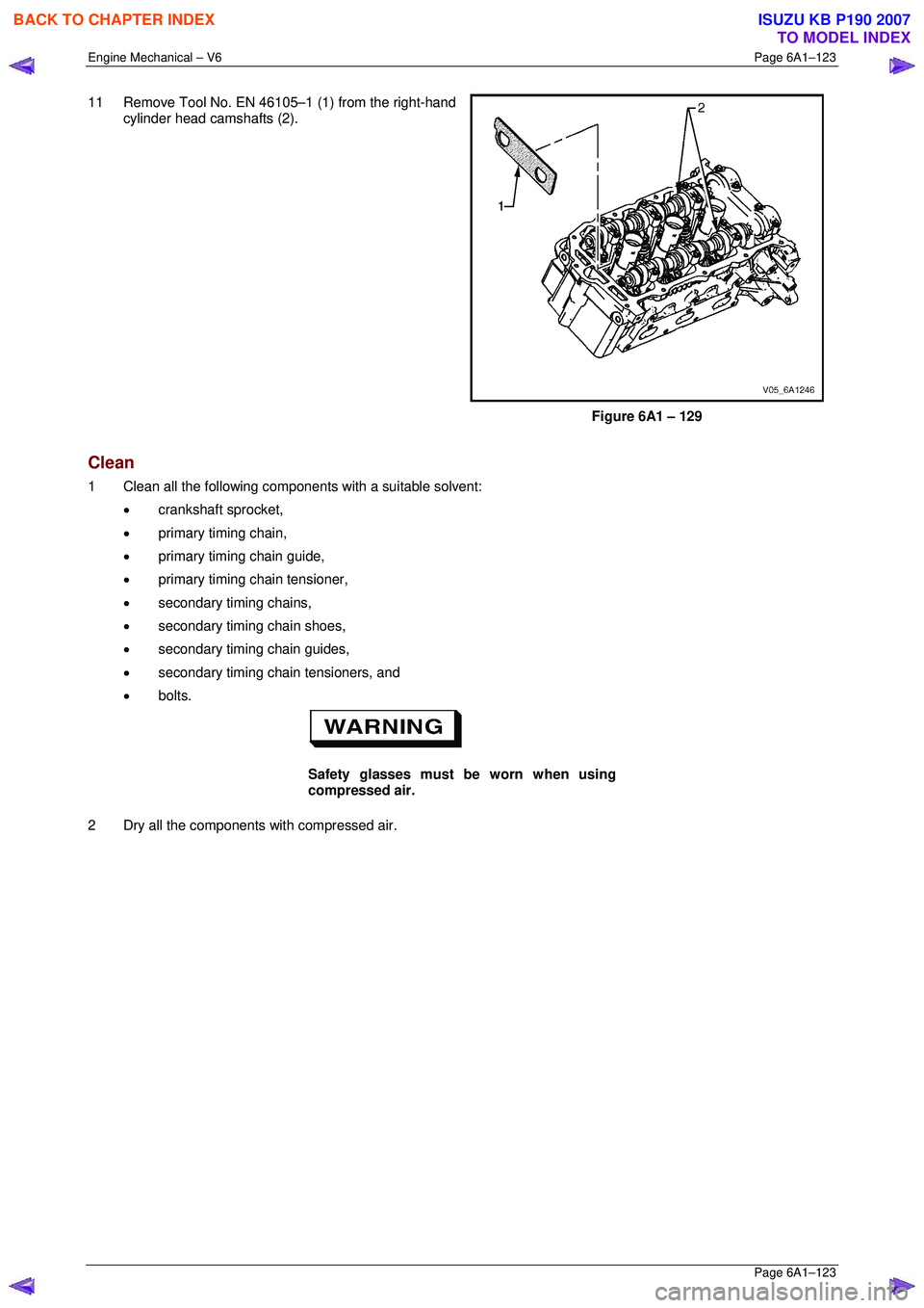
11 Remove Tool No. EN 46105–1 (1) from the right-hand
cylinder head camshafts (2).
Figure 6A1 – 129
Clean
1 Clean all the following components with a suitable solvent:
• crankshaft sprocket,
• primary timing chain,
• primary timing chain guide,
• primary timing chain tensioner,
• secondary timing chains,
• secondary timing chain shoes,
• secondary timing chain guides,
• secondary timing chain tensioners, and
• bolts.
Safety glasses must be worn when using
compressed air.
2 Dry all the components with compressed air.
BACK TO CHAPTER INDEX
TO MODEL INDEX
ISUZU KB P190 2007
Trending: center console, fuse, change key battery, front differential, change time, Alarm, relay
