ISUZU KB P190 2007 Workshop Repair Manual
Manufacturer: ISUZU, Model Year: 2007, Model line: KB P190, Model: ISUZU KB P190 2007Pages: 6020, PDF Size: 70.23 MB
Page 3201 of 6020
Engine Cooling – V6 Engine Page 6B1–66
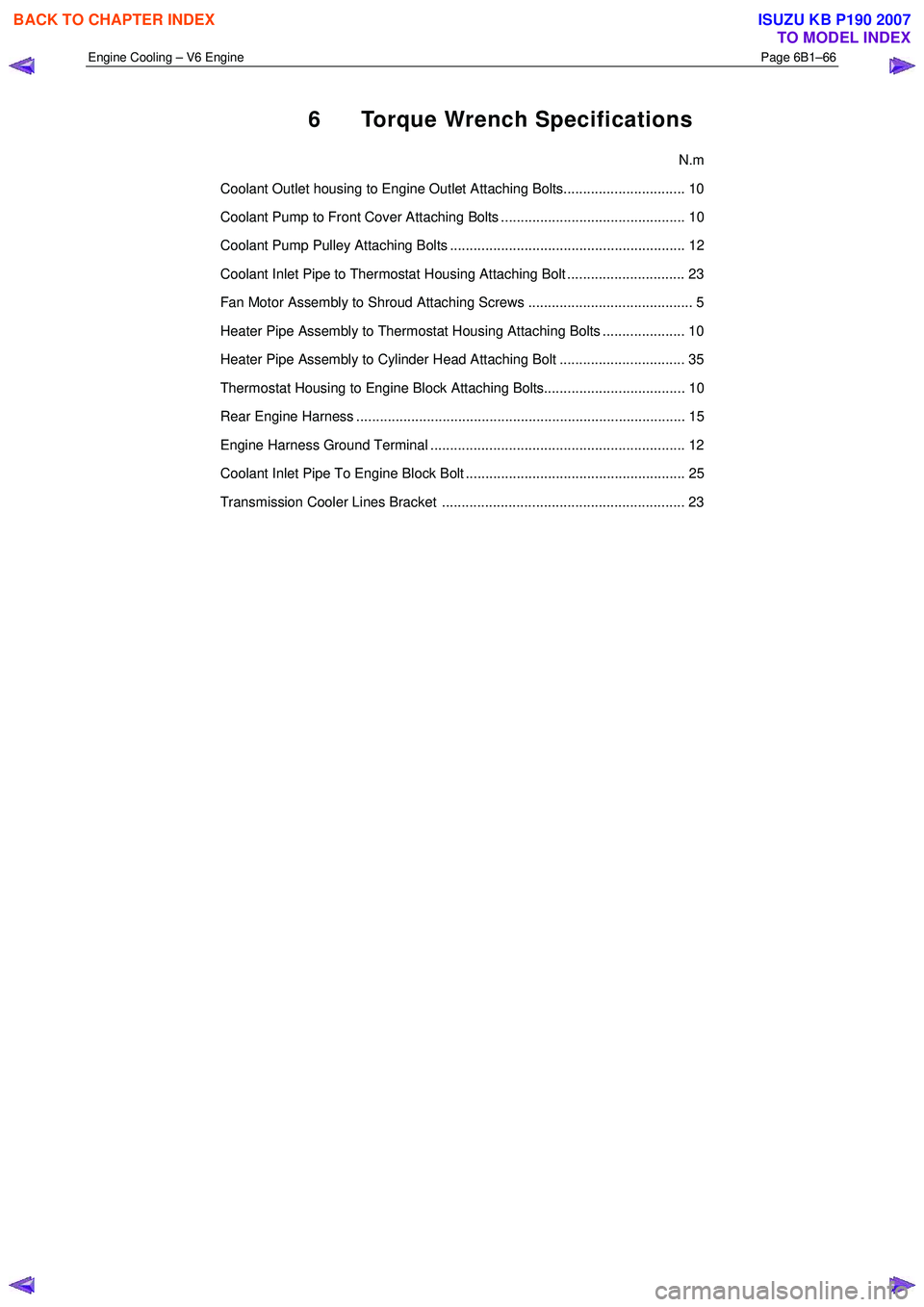
6 Torque Wrench Specifications
N.m
Coolant Outlet housing to Engine Outlet Attaching Bolts............................... 10
Coolant Pump to Front Cover Attaching Bolts ............................................... 10
Coolant Pump Pulley Attaching Bolts ............................................................ 12
Coolant Inlet Pipe to Thermostat Housing Attaching Bolt .............................. 23
Fan Motor Assembly to Shroud Attaching Screws .......................................... 5
Heater Pipe Assembly to Thermostat Housing Attaching Bolts ..................... 10
Heater Pipe Assembly to Cylinder Head Attaching Bolt ................................ 35
Thermostat Housing to Engine Block Attaching Bolts.................................... 10
Rear Engine Harness .................................................................................... 15
Engine Harness Ground Terminal ................................................................. 12
Coolant Inlet Pipe To Engine Block Bolt ........................................................ 25
Transmission Cooler Lines Bracket .............................................................. 23
BACK TO CHAPTER INDEX
TO MODEL INDEX
ISUZU KB P190 2007
Page 3202 of 6020
Engine Cooling – V6 Engine Page 6B1–67
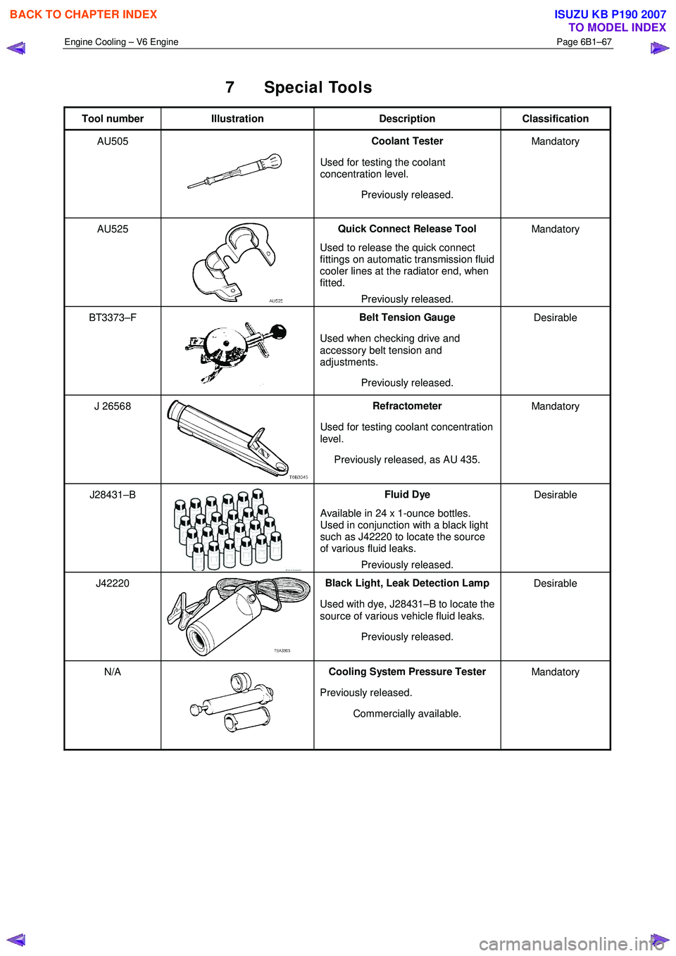
7 Special Tools
Tool number Illustration Description Classification
AU505
Coolant Tester
Used for testing the coolant
concentration level.
Previously released. Mandatory
AU525
Quick Connect Release Tool
Used to release the quick connect
fittings on automatic transmission fluid
cooler lines at the radiator end, when
fitted.
Previously released. Mandatory
BT3373–F
Belt Tension Gauge
Used when checking drive and
accessory belt tension and
adjustments.
Previously released. Desirable
J 26568 Refractometer
Used for testing coolant concentration
level.
Previously released, as AU 435. Mandatory
J28431–B Fluid Dye
Available in 24 x 1-ounce bottles.
Used in conjunction with a black light
such as J42220 to locate the source
of various fluid leaks.
Previously released. Desirable
J42220 Black Light, Leak Detection Lamp
Used with dye, J28431–B to locate the
source of various vehicle fluid leaks.
Previously released. Desirable
N/A Cooling System Pressure Tester
Previously released. Commercially available. Mandatory
BACK TO CHAPTER INDEX
TO MODEL INDEX
ISUZU KB P190 2007
Page 3203 of 6020
Fuel System – V6 Page 6C – 1
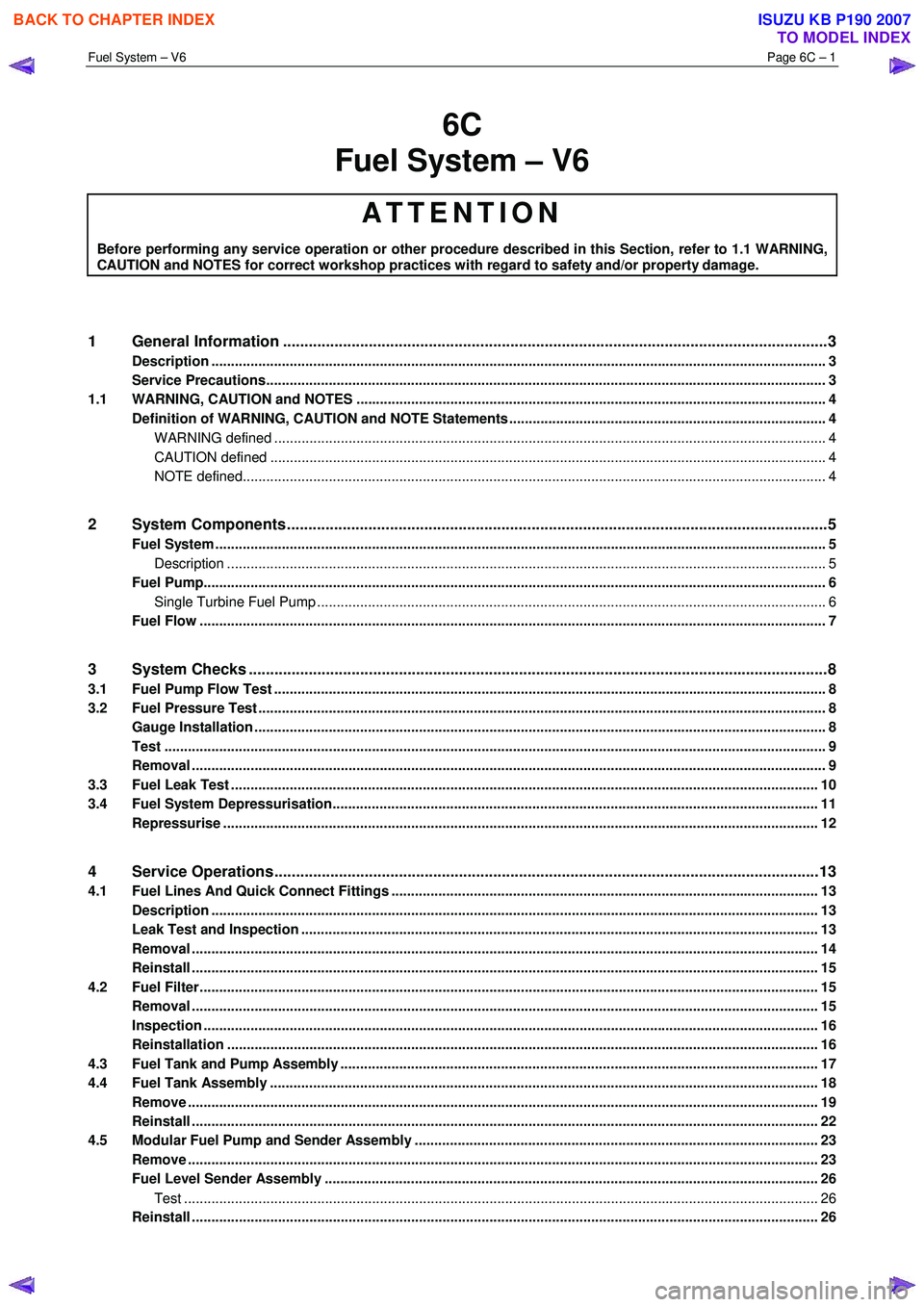
6C
Fuel System – V6
ATTENTION
Before performing any service operation or other procedure described in this Section, refer to 1.1 WARNING,
CAUTION and NOTES for correct workshop practices with regard to safety and/or property damage.
1 General Information ............................................................................................................ ...................3
Description ............................................................................................................................................................. 3
Service Precautions............................................................................................................................................... 3
1.1 WARNING, CAUTION and NOTES ..................................................................................................... ................... 4
Definition of WARNING, CAUTION and NOTE Statements ............................................................................. .... 4
WARNING defined ............................................................................................................................................. 4
CAUTION defined .............................................................................................................................................. 4
NOTE defined..................................................................................................................................................... 4
2 System Components .............................................................................................................. ................5
Fuel System ............................................................................................................................................................ 5
Description ......................................................................................................................................................... 5
Fuel Pump............................................................................................................................................................... 6
Single Turbine Fuel Pump ....................................................................................................... ........................... 6
Fuel Flow ................................................................................................................................................................ 7
3 System Checks .......................................................................................................................................8
3.1 Fuel Pump Flow Test ............................................................................................................................................. 8
3.2 Fuel Pressure Test ................................................................................................................................................. 8
Gauge Installation .................................................................................................................................................. 8
Test ......................................................................................................................................................................... 9
Removal .................................................................................................................................................................. 9
3.3 Fuel Leak Test ...................................................................................................................................................... 10
3.4 Fuel System Depressurisation................................................................................................... ......................... 11
Repressurise ........................................................................................................................................................ 12
4 Service Operations ...............................................................................................................................13
4.1 Fuel Lines And Quick Connect Fittings .......................................................................................... ................... 13
Description ........................................................................................................................................................... 13
Leak Test and Inspection .................................................................................................................................... 13
Removal ................................................................................................................................................................ 14
Reinstall ................................................................................................................................................................ 15
4.2 Fuel Filter.............................................................................................................................................................. 15
Removal ........................................................................................................................ ........................................ 15
Inspection ............................................................................................................................................................. 16
Reinstallation ................................................................................................................. ...................................... 16
4.3 Fuel Tank and Pump Assembly .................................................................................................... ...................... 17
4.4 Fuel Tank Assembly ............................................................................................................................................ 18
Remove ................................................................................................................................................................. 19
Reinstall ................................................................................................................................................................ 22
4.5 Modular Fuel Pump and Sender Assembly .......................................................................................... ............. 23
Remove ................................................................................................................................................................. 23
Fuel Level Sender Assembly ..................................................................................................... ......................... 26
Test .................................................................................................................................................................. 26
Reinstall ................................................................................................................................................................ 26
BACK TO CHAPTER INDEX
TO MODEL INDEX
ISUZU KB P190 2007
Page 3204 of 6020
Fuel System – V6 Page 6C – 2
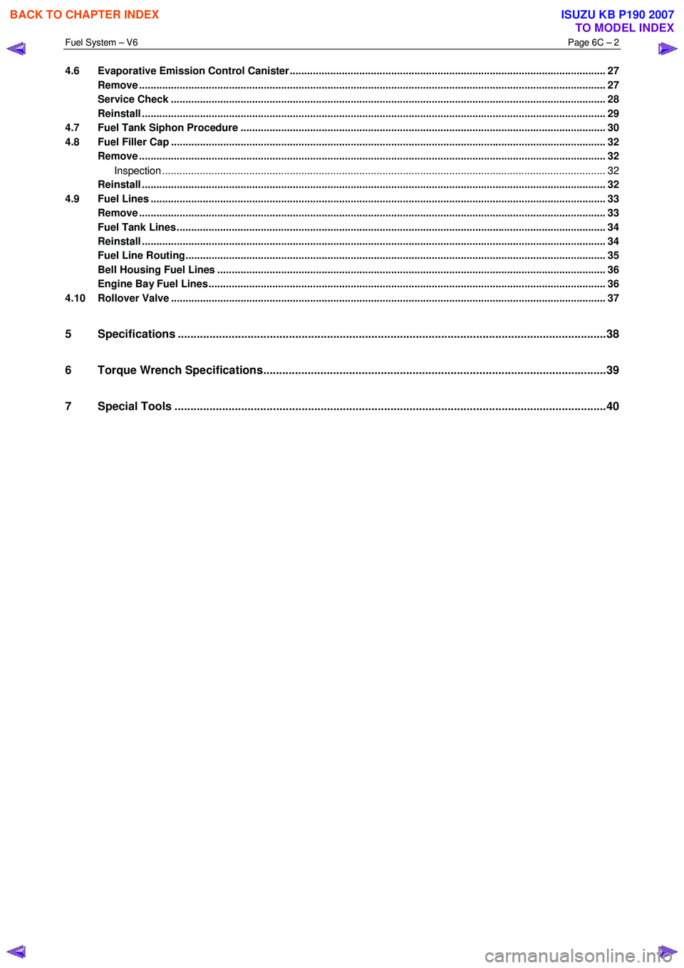
4.6 Evaporative Emission Control Canister............................................................................................................. 27
Remove ................................................................................................................................................................. 27
Service Check .................................................................................................................. .................................... 28
Reinstall ................................................................................................................................................................ 29
4.7 Fuel Tank Siphon Procedure ..................................................................................................... ......................... 30
4.8 Fuel Filler Cap ...................................................................................................................................................... 32
Remove ................................................................................................................................................................. 32
Inspection ......................................................................................................................................................... 32
Reinstall ................................................................................................................................................................ 32
4.9 Fuel Lines ..................................................................................................................... ........................................ 33
Remove ................................................................................................................................................................. 33
Fuel Tank Lines ................................................................................................................ .................................... 34
Reinstall ................................................................................................................................................................ 34
Fuel Line Routing.............................................................................................................. ................................... 35
Bell Housing Fuel Lines ........................................................................................................ .............................. 36
Engine Bay Fuel Lines......................................................................................................................................... 36
4.10 Rollover Valve ...................................................................................................................................................... 37
5 Specifications .......................................................................................................................................38
6 Torque Wrench Specifications................................................................................................... .........39
7 Special Tools ........................................................................................................................................40
BACK TO CHAPTER INDEX
TO MODEL INDEX
ISUZU KB P190 2007
Page 3205 of 6020
Fuel System – V6 Page 6C – 3
1 General Information
Description
Fuel is injected into the engine by separate fuel injectors that are mounted in the intake manifold (common chamber).
Fuel is supplied to the injectors under pressure from the fuel tank through the fuel lines and the fuel rail, which is
attached to the top of the common chamber.
A fuel pressure control valve is installed on the fuel rail to maintain fuel line pressure across the injectors under all
operating conditions. Fuel pressure is maintained by controlling the amount of fuel that is supplied from the fuel tank,
based on the demand of the engine via the engine control module (ECM).
Two interchangeable “O” rings are used on the fuel injector and must be replaced when the injectors are removed.
The Multiport Fuel Injection system utilizes an injection system where the injectors turn on at every crankshaft revolution.
The ECM controls the injector on time so that the correct amount of fuel is metered depending on driving conditions.
The V6 engine is designed to use only unleaded petrol.
Unleaded petrol must be used for correct emission control system operation and its use will also minimize spark plug
fouling and extend engine oil life.
Using leaded petrol can damage the emission control system and could void the vehicle warranty. All vehicles are
equipped with an Evaporative Emission Control System. The purpose of the system is to minimize the escape of fuel
vapours into the atmosphere.
Service Precautions
• Use extreme care when working on the fuel system and follow all safety precautions.
• W hen working on the fuel system, disconnect the battery ground cable except for tests where battery voltage is
required.
• Always keep a dry chemical (class B) fire extinguisher near the work area.
• Relace all fuel lines and fittings with the same type of line and fitting as those removed.
• Clean and inspect “O” rings carefully and replace if required.
• Always depressurize the fuel lines before servicing any fuel system components.
• Do not attempt any repairs on the fuel system until, all warnings and instructions, relating to that repair have been
read and ensure all notices and cautions are adhered to.
• Do not allow any naked frames or sparks near the work area when working on the fuel system.
• If draining of the fuel system is required, this should be done in a well ventilated area.
• Protect the fuel lines and associated parts from thermal damage, spattering when welding.
BACK TO CHAPTER INDEX
TO MODEL INDEX
ISUZU KB P190 2007
Page 3206 of 6020

Fuel System – V6 Page 6C – 4
1.1 WARNING, CAUTION and NOTES
This Section contains various W ARNINGS, CAUTIONS and NOTE statements that you must observe carefully to reduce
the risk of death or injury during service, repair procedures or vehicle operation. Incorrect service or repair procedures
may damage the vehicle or cause operational faults. W ARNINGS, CAUTION and NOTE statements are not exhaustive.
GM HOLDEN LTD can not possibly warn of all the potentially hazardous consequences of failure to follow these
instructions.
Definition of WARNING, CAUTION and NOTE Statements
Diagnosis and repair procedures in this Section contain both general and specific W ARNING, CAUTION and NOTE
statements. GM HOLDEN LTD is dedicated to the presentation of service information that helps the technician to
diagnose and repair the systems necessary for proper operation of the vehicle. Certain procedures may present a hazard
to the technician if they are not followed in the recommended manner. W ARNING, CAUTION and NOTE statements are
designed to help prevent these hazards from occurring, but not all hazards can be foreseen.
WARNING defined
A W ARNING statement immediately precedes an operating procedure or maintenance practice which, if not correctly
followed, could result in death or injury. A W ARNING statement alerts you to take necessary action or not to take a
prohibited action. If a W ARNING statement is ignored, the following consequences may occur:
• Death or injury to the technician or other personnel working on the vehicle,
• Death or injury to other people in or near the workplace area, and / or
• Death or injury to the driver / or passenger(s) of the vehicle or other people, if the vehicle has been improperly
repaired.
CAUTION defined
A CAUTION statement immediately precedes an operating procedure or maintenance practice which, if not correctly
followed, could result in damage to or destruction of equipment, or corruption of data. If a CAUTION statement is ignored,
the following consequences may occur:
• Damage to the vehicle,
• Unnecessary vehicle repairs or component replacement,
• Faulty operation or performance of any system or component being repaired,
• Damage to any system or components which depend on the proper operation of the system or component being
repaired,
• Faulty operation or performance of any systems or components which depend on the proper operation or
performance of the system or component under repair,
• Damage to fasteners, basic tools or special tools and / or
• Leakage of coolant, lubricant or other vital fluids.
NOTE defined
A NOTE statement immediately precedes or follows an operating procedure, maintenance practice or condition that
requires highlighting. A NOTE statement also emphasises necessary characteristics of a diagnostic or repair procedure.
A NOTE statement is designed to:
• Clarify a procedure,
• Present additional information for accomplishing a procedure,
• Give insight into the reasons for performing a procedure in the recommended manner, and / or
• Present information that gives the technician the benefit of past experience in accomplishing a procedure with
greater ease.
BACK TO CHAPTER INDEX
TO MODEL INDEX
ISUZU KB P190 2007
Page 3207 of 6020
Fuel System – V6 Page 6C – 5
2 System Components
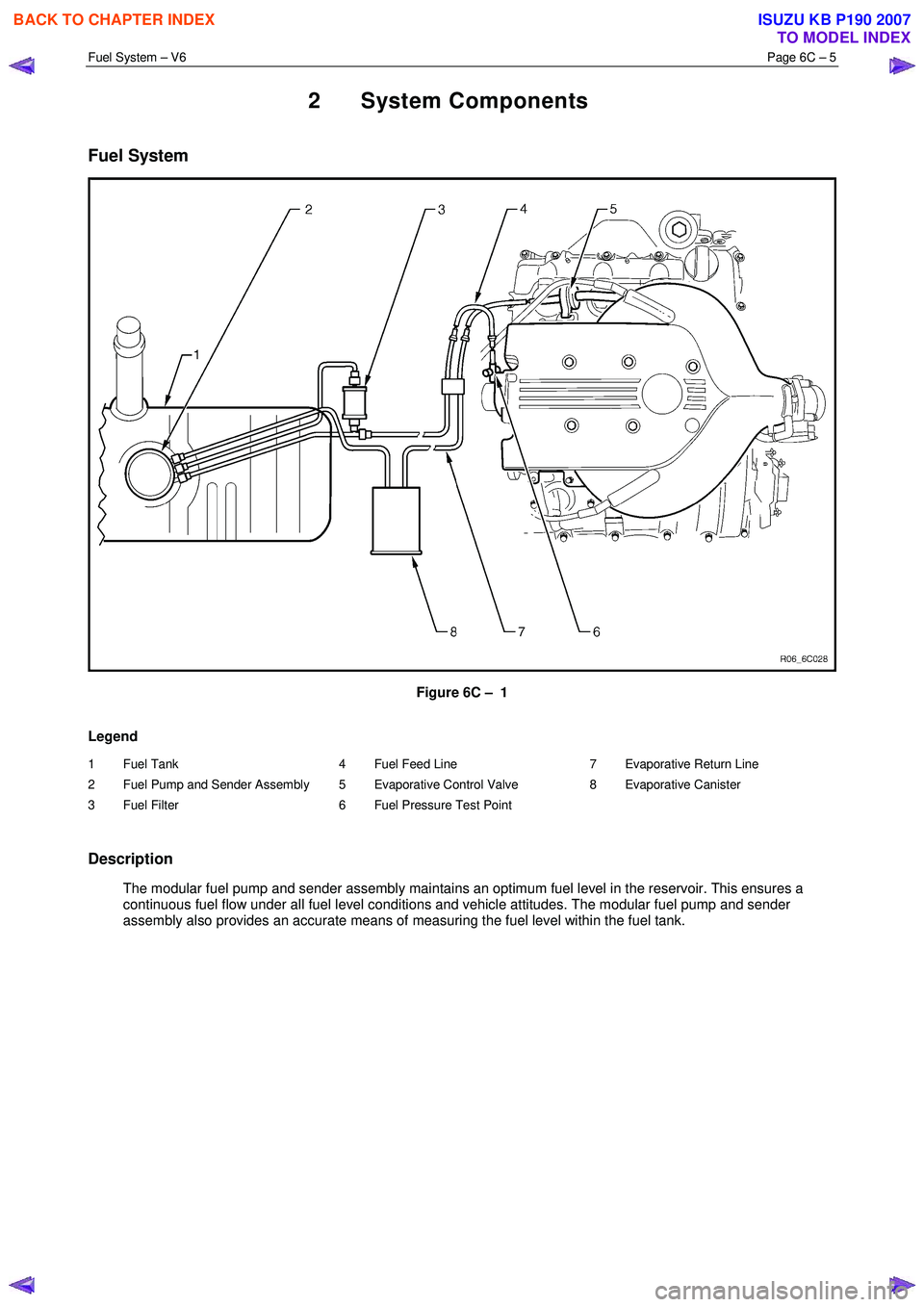
Fuel System
Figure 6C – 1
Legend
1 Fuel Tank
2 Fuel Pump and Sender Assembly
3 Fuel Filter 4 Fuel Feed Line
5 Evaporative Control Valve
6 Fuel Pressure Test Point 7 Evaporative Return Line
8 Evaporative Canister
Description
The modular fuel pump and sender assembly maintains an optimum fuel level in the reservoir. This ensures a continuous fuel flow under all fuel level conditions and vehicle attitudes. The modular fuel pump and sender
assembly also provides an accurate means of measuring the fuel level within the fuel tank.
BACK TO CHAPTER INDEX
TO MODEL INDEX
ISUZU KB P190 2007
Page 3208 of 6020
Fuel System – V6 Page 6C – 6
Fuel Pump
Single Turbine Fuel Pump
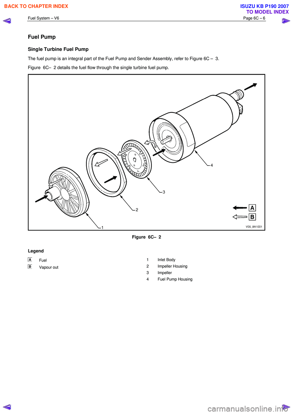
The fuel pump is an integral part of the Fuel Pump and Sender Assembly, refer to Figure 6C – 3.
Figure 6C– 2 details the fuel flow through the single turbine fuel pump.
Figure 6C– 2
Legend
Fuel
Vapour out 1 Inlet Body
2 Impeller Housing
3 Impeller
4 Fuel Pump Housing
BACK TO CHAPTER INDEX
TO MODEL INDEX
ISUZU KB P190 2007
Page 3209 of 6020
Fuel System – V6 Page 6C – 7
Fuel Flow
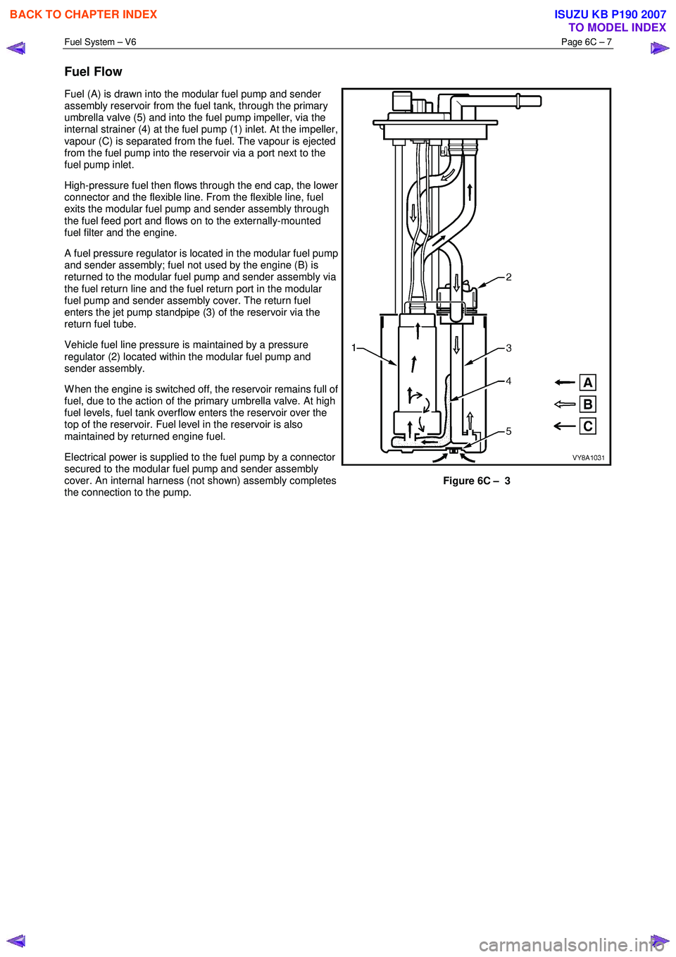
Fuel (A) is drawn into the modular fuel pump and sender
assembly reservoir from the fuel tank, through the primary
umbrella valve (5) and into the fuel pump impeller, via the
internal strainer (4) at the fuel pump (1) inlet. At the impeller,
vapour (C) is separated from the fuel. The vapour is ejected
from the fuel pump into the reservoir via a port next to the
fuel pump inlet.
High-pressure fuel then flows through the end cap, the lower
connector and the flexible line. From the flexible line, fuel
exits the modular fuel pump and sender assembly through
the fuel feed port and flows on to the externally-mounted
fuel filter and the engine.
A fuel pressure regulator is located in the modular fuel pump
and sender assembly; fuel not used by the engine (B) is
returned to the modular fuel pump and sender assembly via
the fuel return line and the fuel return port in the modular
fuel pump and sender assembly cover. The return fuel
enters the jet pump standpipe (3) of the reservoir via the
return fuel tube.
Vehicle fuel line pressure is maintained by a pressure
regulator (2) located within the modular fuel pump and
sender assembly.
W hen the engine is switched off, the reservoir remains full of
fuel, due to the action of the primary umbrella valve. At high
fuel levels, fuel tank overflow enters the reservoir over the
top of the reservoir. Fuel level in the reservoir is also
maintained by returned engine fuel.
Electrical power is supplied to the fuel pump by a connector
secured to the modular fuel pump and sender assembly
cover. An internal harness (not shown) assembly completes
the connection to the pump.
Figure 6C – 3
BACK TO CHAPTER INDEX
TO MODEL INDEX
ISUZU KB P190 2007
Page 3210 of 6020

Fuel System – V6 Page 6C – 8
3 System Checks
3.1 Fuel Pump Flow Test
If a reduction of the fuel supply is suspected, perform the following checks.
1 Ensure there is sufficient fuel in the tank.
2 W ith the engine running, check the fuel lines from the fuel tank to the injectors for evidence of leakage.
Retighten, if the lines or the connections are loose.
Also, check the fuel lines for restrictions such as
squashed or clogged fuel line.
3 Depressurize the fuel system, refer to 3.4 Fuel System Depressurisation.
4 Disconnect the fuel line at the fuel rail.
5 Connect a hose from the fuel line and place the open end into a clean container.
6 Connect the fuel pump relay terminals (2) with a jumper wire (1) as shown, then turn the ignition to the
ON position to operate the fuel pump, then check the
fuel pump flow rate.
Do not generate any sparks when connecting
the jumper wire.
Fuel delivery test time ....................................... 15.0 Sec
Fuel delivery rate .....................................0.38 Litres Min
NOTE
If the fuel flow rate is below the minimum value,
conduct a fuel pressure test, refer to 3.2
Fuel Pressure Test.
Figure 6C – 4
3.2 Fuel Pressure Test
To reduce the risk of fire or personal injury,
depressurise the fuel system before servicing
any fuel system components, refer to 3.4
Fuel System Depressurisation.
Gauge Installation
1 Turn the ignition switch off.
2 Depressurise the fuel system, refer to 3.4 Fuel System Depressurisation.
BACK TO CHAPTER INDEX
TO MODEL INDEX
ISUZU KB P190 2007