ISUZU KB P190 2007 Workshop Repair Manual
Manufacturer: ISUZU, Model Year: 2007, Model line: KB P190, Model: ISUZU KB P190 2007Pages: 6020, PDF Size: 70.23 MB
Page 3211 of 6020
Fuel System – V6 Page 6C – 9
A small amount of fuel may be released when
connecting the fuel pressure gauge to the fuel
pressure test point. Cover the fittings with a
shop towel to absorb any fuel spillage before
connecting the fuel pressure gauge. After the
fuel pressure test procedure, place the soiled
towel in an approved container for disposal.
3 At the fuel pressure test point, remove the Schrader valve sealing cap.
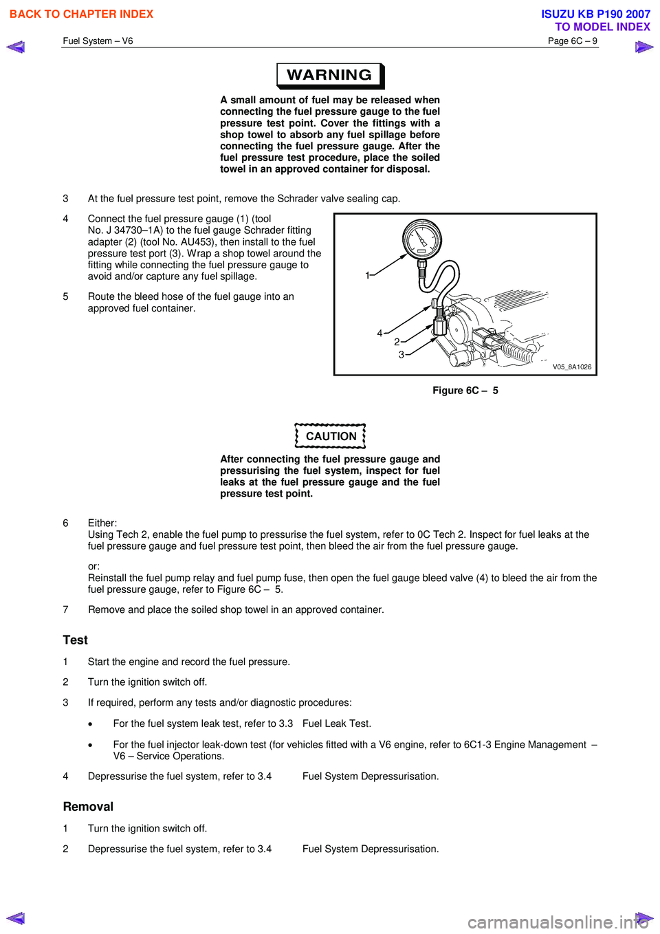
4 Connect the fuel pressure gauge (1) (tool No. J 34730–1A) to the fuel gauge Schrader fitting
adapter (2) (tool No. AU453), then install to the fuel
pressure test port (3). W rap a shop towel around the
fitting while connecting the fuel pressure gauge to
avoid and/or capture any fuel spillage.
5 Route the bleed hose of the fuel gauge into an approved fuel container.
Figure 6C – 5
After connecting the fuel pressure gauge and
pressurising the fuel system, inspect for fuel
leaks at the fuel pressure gauge and the fuel
pressure test point.
6 Either: Using Tech 2, enable the fuel pump to pressurise the fuel system, refer to 0C Tech 2. Inspect for fuel leaks at the
fuel pressure gauge and fuel pressure test point, then bleed the air from the fuel pressure gauge.
or: Reinstall the fuel pump relay and fuel pump fuse, then open the fuel gauge bleed valve (4) to bleed the air from the
fuel pressure gauge, refer to Figure 6C – 5.
7 Remove and place the soiled shop towel in an approved container.
Test
1 Start the engine and record the fuel pressure.
2 Turn the ignition switch off.
3 If required, perform any tests and/or diagnostic procedures:
• For the fuel system leak test, refer to 3.3 Fuel Leak Test.
• For the fuel injector leak-down test (for vehicles fitted with a V6 engine, refer to 6C1-3 Engine Management –
V6 – Service Operations.
4 Depressurise the fuel system, refer to 3.4 Fuel System Depressurisation.
Removal
1 Turn the ignition switch off.
2 Depressurise the fuel system, refer to 3.4 Fuel System Depressurisation.
BACK TO CHAPTER INDEX
TO MODEL INDEX
ISUZU KB P190 2007
Page 3212 of 6020
Fuel System – V6 Page 6C – 10
After relieving the fuel system pressure, a
small amount of fuel may be released when
servicing the fuel lines or connections. Cover
the fittings with a shop towel before
disconnecting. This catches any leaking fuel.
Place the soiled towel in an approved
container when disconnection is completed.
3 W rap a shop towel around the fuel pressure test point to absorb any fuel spillage.
4 Remove the fuel pressure gauge and drain any fuel remaining in the fuel pressure gauge into an approved fuel container.
5 Remove the soiled shop towel and place in an approved container.
6 Repressurise the fuel system, refer to 3.4 Fuel System Depressurisation.
7 Road-test the vehicle and check for correct operation.
3.3 Fuel Leak Test
After installing any fuel system component
and before starting the engine, check the fuel
system for leaks.
NOTE
For the fuel injector leak-down test (for vehicles
fitted with a V6 engine), refer to 6C1-3 Engine
Management – V6 – Service Operations.
1 Turn the ignition switch on for two seconds.
2 Turn the ignition switch off for 10 seconds.
3 Turn the ignition switch on.
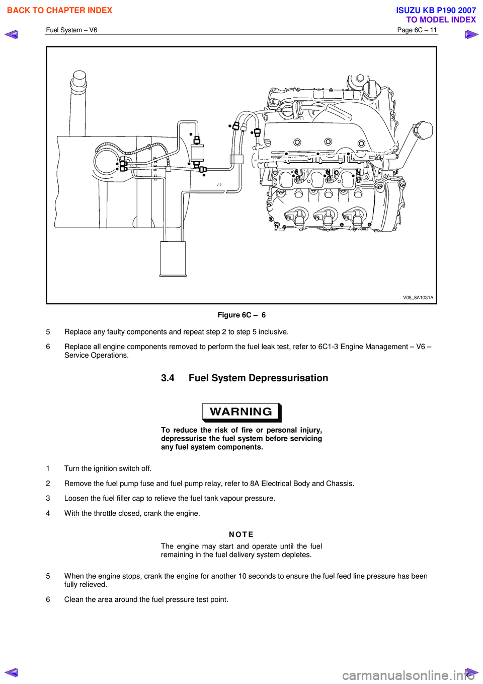
4 Check for fuel leaks, particularly at points marked �z (that is, quick-connect fittings, fuel rails, fuel injectors,
Schrader valve and evaporative emission control canister purge solenoid, refer to Figure 6C – 6.
BACK TO CHAPTER INDEX
TO MODEL INDEX
ISUZU KB P190 2007
Page 3213 of 6020
Fuel System – V6 Page 6C – 11
Figure 6C – 6
5 Replace any faulty components and repeat step 2 to step 5 inclusive.
6 Replace all engine components removed to perform the fuel leak test, refer to 6C1-3 Engine Management – V6 – Service Operations.
3.4 Fuel System Depressurisation
To reduce the risk of fire or personal injury,
depressurise the fuel system before servicing
any fuel system components.
1 Turn the ignition switch off.
2 Remove the fuel pump fuse and fuel pump relay, refer to 8A Electrical Body and Chassis.
3 Loosen the fuel filler cap to relieve the fuel tank vapour pressure.
4 W ith the throttle closed, crank the engine.
NOTE
The engine may start and operate until the fuel
remaining in the fuel delivery system depletes.
5 W hen the engine stops, crank the engine for another 10 seconds to ensure the fuel feed line pressure has been fully relieved.
6 Clean the area around the fuel pressure test point.
BACK TO CHAPTER INDEX
TO MODEL INDEX
ISUZU KB P190 2007
Page 3214 of 6020
Fuel System – V6 Page 6C – 12
A small amount of fuel may be released when
pressing on the Schrader valve. Cover the
fitting with a shop towel to absorb any fuel
spillage before removing the Schrader valve
sealing cap. Place the soiled towel in an
approved container for disposal.
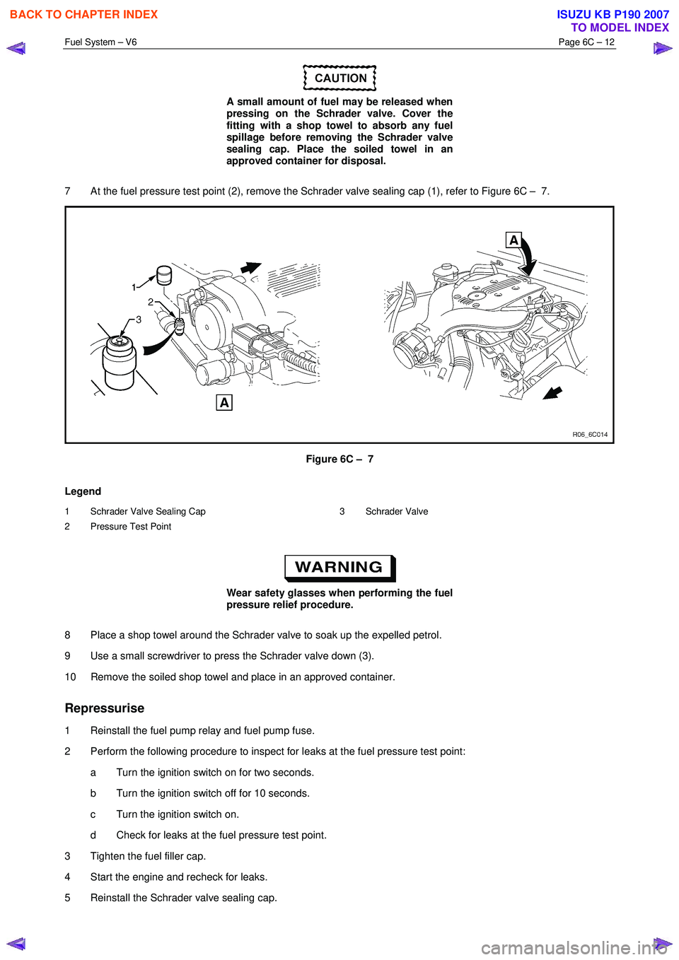
7 At the fuel pressure test point (2), remove the Schrader valve sealing cap (1), refer to Figure 6C – 7.
Figure 6C – 7
Legend
1 Schrader Valve Sealing Cap
2 Pressure Test Point 3 Schrader Valve
Wear safety glasses when performing the fuel
pressure relief procedure.
8 Place a shop towel around the Schrader valve to soak up the expelled petrol.
9 Use a small screwdriver to press the Schrader valve down (3).
10 Remove the soiled shop towel and place in an approved container.
Repressurise
1 Reinstall the fuel pump relay and fuel pump fuse.
2 Perform the following procedure to inspect for leaks at the fuel pressure test point: a Turn the ignition switch on for two seconds.
b Turn the ignition switch off for 10 seconds.
c Turn the ignition switch on.
d Check for leaks at the fuel pressure test point.
3 Tighten the fuel filler cap.
4 Start the engine and recheck for leaks.
5 Reinstall the Schrader valve sealing cap.
BACK TO CHAPTER INDEX
TO MODEL INDEX
ISUZU KB P190 2007
Page 3215 of 6020
Fuel System – V6 Page 6C – 13
4 Service Operations
4.1 Fuel Lines And Quick Connect Fittings
Description
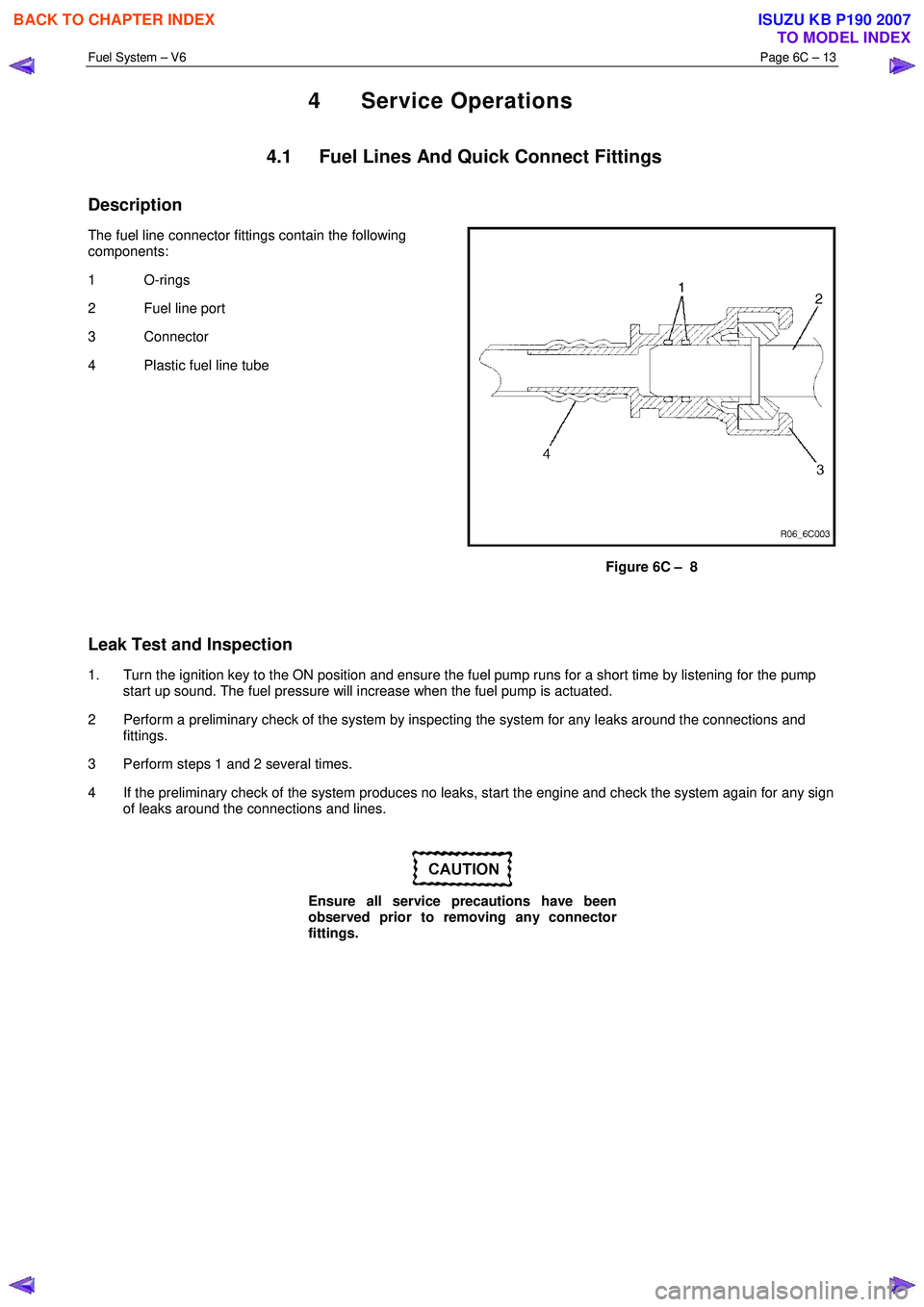
The fuel line connector fittings contain the following
components:
1 O-rings
2 Fuel line port
3 Connector
4 Plastic fuel line tube
Figure 6C – 8
Leak Test and Inspection
1. Turn the ignition key to the ON position and ensure the fuel pump runs for a short time by listening for the pump start up sound. The fuel pressure will increase when the fuel pump is actuated.
2 Perform a preliminary check of the system by inspecting the system for any leaks around the connections and fittings.
3 Perform steps 1 and 2 several times.
4 If the preliminary check of the system produces no leaks, start the engine and check the system again for any sign of leaks around the connections and lines.
Ensure all service precautions have been
observed prior to removing any connector
fittings.
BACK TO CHAPTER INDEX
TO MODEL INDEX
ISUZU KB P190 2007
Page 3216 of 6020
Fuel System – V6 Page 6C – 14
Removal
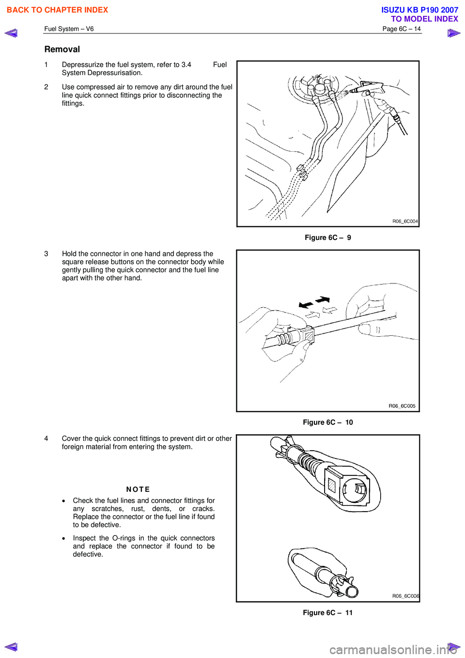
1 Depressurize the fuel system, refer to 3.4 Fuel
System Depressurisation.
2 Use compressed air to remove any dirt around the fuel line quick connect fittings prior to disconnecting the
fittings.
Figure 6C – 9
3 Hold the connector in one hand and depress the square release buttons on the connector body while
gently pulling the quick connector and the fuel line
apart with the other hand.
Figure 6C – 10
4 Cover the quick connect fittings to prevent dirt or other foreign material from entering the system.
NOTE
• Check the fuel lines and connector fittings for
any scratches, rust, dents, or cracks.
Replace the connector or the fuel line if found
to be defective.
• Inspect the O-rings in the quick connectors
and replace the connector if found to be
defective.
Figure 6C – 11
BACK TO CHAPTER INDEX
TO MODEL INDEX
ISUZU KB P190 2007
Page 3217 of 6020
Fuel System – V6 Page 6C – 15
Reinstall
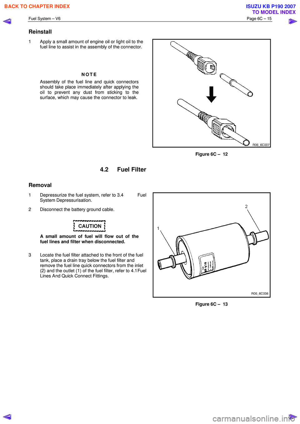
1 Apply a small amount of engine oil or light oil to the
fuel line to assist in the assembly of the connector.
NOTE
Assembly of the fuel line and quick connectors
should take place immediately after applying the
oil to prevent any dust from sticking to the
surface, which may cause the connector to leak.
Figure 6C – 12
4.2 Fuel Filter
Removal
1 Depressurize the fuel system, refer to 3.4 Fuel
System Depressurisation.
2 Disconnect the battery ground cable.
A small amount of fuel will flow out of the
fuel lines and filter when disconnected.
3 Locate the fuel filter attached to the front of the fuel tank, place a drain tray below the fuel filter and
remove the fuel line quick connectors from the inlet
(2) and the outlet (1) of the fuel filter, refer to 4.1 Fuel
Lines And Quick Connect Fittings.
Figure 6C – 13
BACK TO CHAPTER INDEX
TO MODEL INDEX
ISUZU KB P190 2007
Page 3218 of 6020
Fuel System – V6 Page 6C – 16
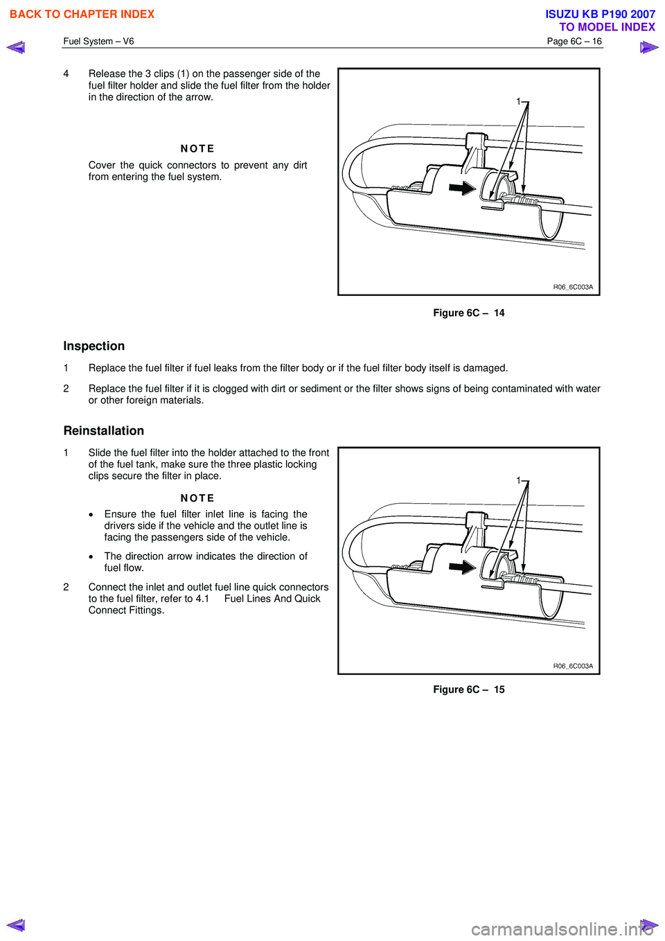
4 Release the 3 clips (1) on the passenger side of the
fuel filter holder and slide the fuel filter from the holder
in the direction of the arrow.
NOTE
Cover the quick connectors to prevent any dirt
from entering the fuel system.
Figure 6C – 14
Inspection
1 Replace the fuel filter if fuel leaks from the filter body or if the fuel filter body itself is damaged.
2 Replace the fuel filter if it is clogged with dirt or sediment or the filter shows signs of being contaminated with water or other foreign materials.
Reinstallation
1 Slide the fuel filter into the holder attached to the front of the fuel tank, make sure the three plastic locking
clips secure the filter in place.
NOTE
• Ensure the fuel filter inlet line is facing the
drivers side if the vehicle and the outlet line is
facing the passengers side of the vehicle.
• The direction arrow indicates the direction of
fuel flow.
2 Connect the inlet and outlet fuel line quick connectors to the fuel filter, refer to 4.1 Fuel Lines And Quick
Connect Fittings.
Figure 6C – 15
BACK TO CHAPTER INDEX
TO MODEL INDEX
ISUZU KB P190 2007
Page 3219 of 6020
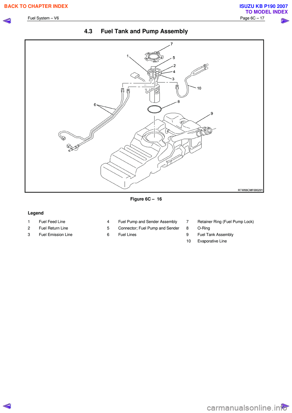
Fuel System – V6 Page 6C – 17
4.3 Fuel Tank and Pump Assembly
Figure 6C – 16
Legend
1 Fuel Feed Line
2 Fuel Return Line
3 Fuel Emission Line
4 Fuel Pump and Sender Assembly
5 Connector; Fuel Pump and Sender
6 Fuel Lines
7 Retainer Ring (Fuel Pump Lock)
8 O-Ring
9 Fuel Tank Assembly
10 Evaporative Line
BACK TO CHAPTER INDEX
TO MODEL INDEX
ISUZU KB P190 2007
Page 3220 of 6020
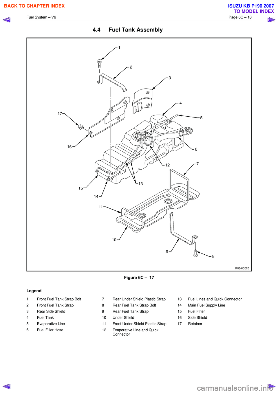
Fuel System – V6 Page 6C – 18
4.4 Fuel Tank Assembly
Figure 6C – 17
Legend
1 Front Fuel Tank Strap Bolt
2 Front Fuel Tank Strap
3 Rear Side Shield
4 Fuel Tank
5 Evaporative Line
6 Fuel Filler Hose 7 Rear Under Shield Plastic Strap
8 Rear Fuel Tank Strap Bolt
9 Rear Fuel Tank Strap
10 Under Shield
11 Front Under Shield Plastic Strap
12 Evaporative Line and Quick Connector 13 Fuel Lines and Quick Connector
14 Main Fuel Supply Line
15 Fuel Filter
16 Side Shield
17 Retainer
BACK TO CHAPTER INDEX
TO MODEL INDEX
ISUZU KB P190 2007