ISUZU KB P190 2007 Workshop Repair Manual
Manufacturer: ISUZU, Model Year: 2007, Model line: KB P190, Model: ISUZU KB P190 2007Pages: 6020, PDF Size: 70.23 MB
Page 3631 of 6020
Starting System – V6 Page 6D1-2–23
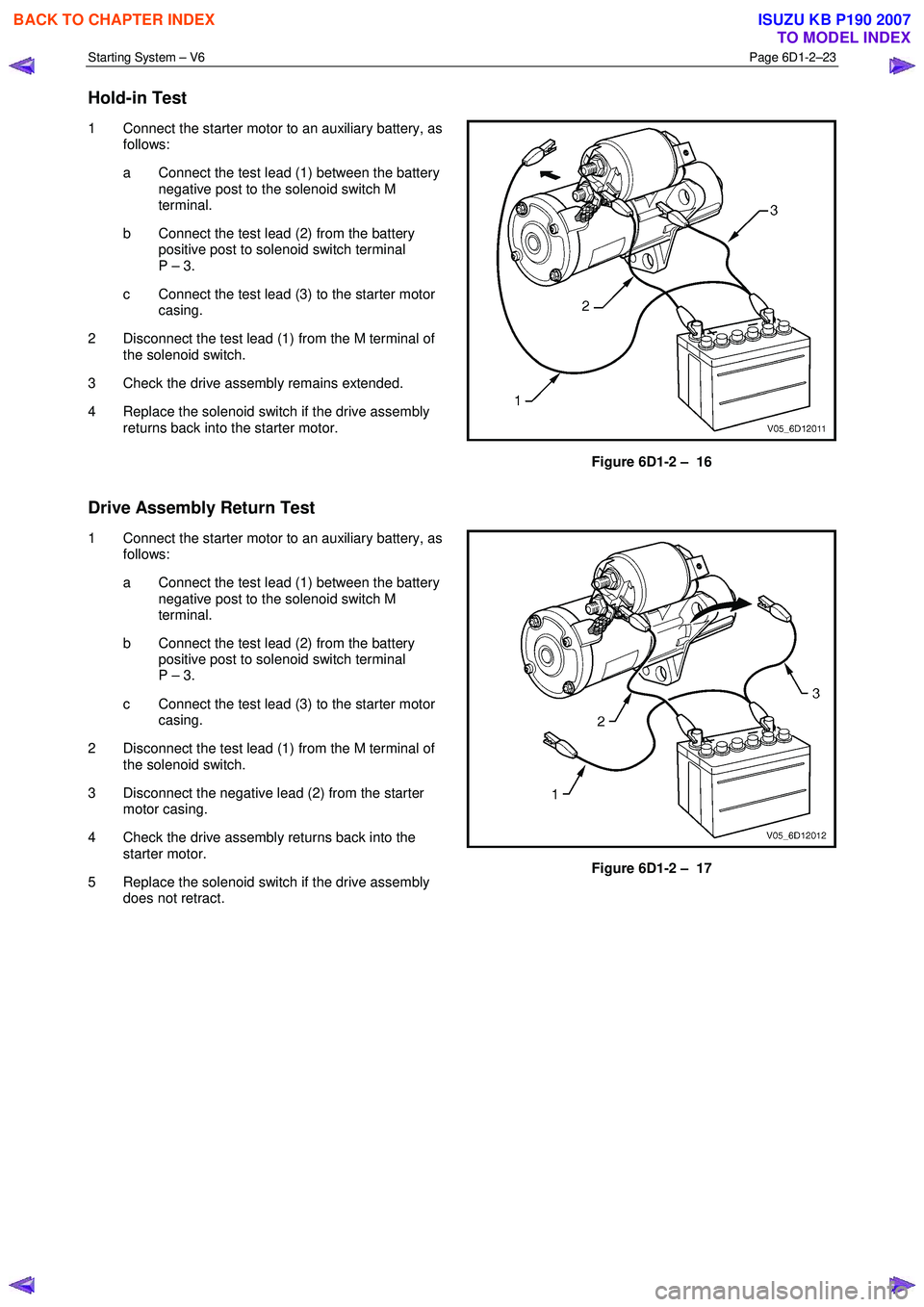
Hold-in Test
1 Connect the starter motor to an auxiliary battery, as
follows:
a Connect the test lead (1) between the battery negative post to the solenoid switch M
terminal.
b Connect the test lead (2) from the battery positive post to solenoid switch terminal
P – 3.
c Connect the test lead (3) to the starter motor casing.
2 Disconnect the test lead (1) from the M terminal of the solenoid switch.
3 Check the drive assembly remains extended.
4 Replace the solenoid switch if the drive assembly returns back into the starter motor.
Figure 6D1-2 – 16
Drive Assembly Return Test
1 Connect the starter motor to an auxiliary battery, as follows:
a Connect the test lead (1) between the battery negative post to the solenoid switch M
terminal.
b Connect the test lead (2) from the battery positive post to solenoid switch terminal
P – 3.
c Connect the test lead (3) to the starter motor casing.
2 Disconnect the test lead (1) from the M terminal of the solenoid switch.
3 Disconnect the negative lead (2) from the starter motor casing.
4 Check the drive assembly returns back into the starter motor.
5 Replace the solenoid switch if the drive assembly does not retract.
Figure 6D1-2 – 17
BACK TO CHAPTER INDEX
TO MODEL INDEX
ISUZU KB P190 2007
Page 3632 of 6020
Starting System – V6 Page 6D1-2–24
No Load Test
1 Clamp the starter motor securely to a test bench.
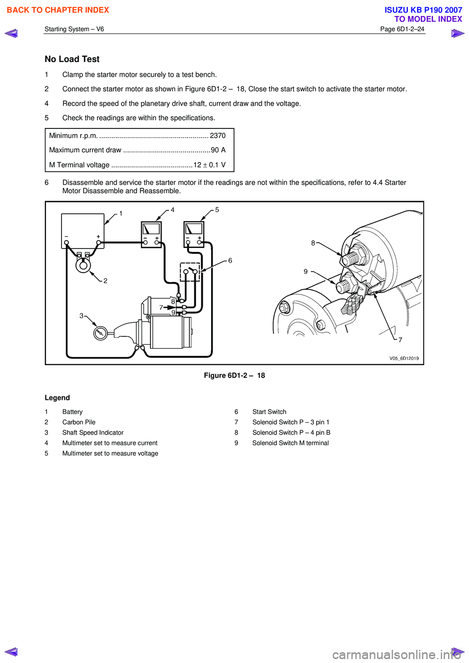
2 Connect the starter motor as shown in Figure 6D1-2 – 18, Close the start switch to activate the starter motor.
4 Record the speed of the planetary drive shaft, current draw and the voltage.
5 Check the readings are within the specifications.
Minimum r.p.m. ....................................................... 2370
Maximum current draw ............................................ 90 A
M Terminal voltage ......................................... 12 ± 0.1 V
6 Disassemble and service the starter motor if the readings are not within the specifications, refer to 4.4 Starter
Motor Disassemble and Reassemble.
Figure 6D1-2 – 18
Legend
1 Battery
2 Carbon Pile
3 Shaft Speed Indicator
4 Multimeter set to measure current
5 Multimeter set to measure voltage 6 Start Switch
7 Solenoid Switch P – 3 pin 1
8 Solenoid Switch P – 4 pin B
9 Solenoid Switch M terminal
BACK TO CHAPTER INDEX
TO MODEL INDEX
ISUZU KB P190 2007
Page 3633 of 6020
Starting System – V6 Page 6D1-2–25
4.4 Starter Motor Disassemble and
Reassemble
Disassemble
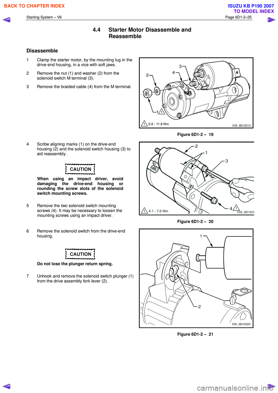
1 Clamp the starter motor, by the mounting lug in the drive-end housing, in a vice with soft jaws.
2 Remove the nut (1) and washer (2) from the solenoid switch M terminal (3).
3 Remove the braided cable (4) from the M terminal.
Figure 6D1-2 – 19
4 Scribe aligning marks (1) on the drive-end housing (2) and the solenoid switch housing (3) to
aid reassembly.
When using an impact driver, avoid
damaging the drive-end housing or
rounding the screw slots of the solenoid
switch mounting screws.
5 Remove the two solenoid switch mounting screws (4). It may be necessary to loosen the
mounting screws using an impact driver.
Figure 6D1-2 – 20
6 Remove the solenoid switch from the drive-end housing.
Do not lose the plunger return spring.
7 Unhook and remove the solenoid switch plunger (1) from the drive assembly fork lever (2).
Figure 6D1-2 – 21
BACK TO CHAPTER INDEX
TO MODEL INDEX
ISUZU KB P190 2007
Page 3634 of 6020

Starting System – V6 Page 6D1-2–26
Reassemble
1 Reassemble the solenoid in the reverse order of the disassembly procedure noting the following points.
Dry all parts thoroughly before assembly,
taking care not to breathe in any vapours.
2 Lightly coat the solenoid switch plunger with 10% molybdenum disulphide grease.
Excess grease can enter the contact chamber
of the solenoid switch and cause contact
problems. Do not use too much grease.
3 Hook the plunger over the fork lever.
4 Insert the return spring into the plunger.
5 Slide solenoid switch over the plunger.
6 Align the solenoid switch with drive-end housing ensuring the solenoid switch terminal P – 4 faces away from the pole housing.
7 Install and tighten the solenoid switch mounting screws.
Solenoid switch mounting screw
torque specification .....................................4.1 – 7.6 Nm
8 W ith the starter motor reassembled, perform a No Load Test, refer to 4.3 Starter Motor Bench Tests.
9 If the starter motor fails the No Load Test specification, replace the starter motor.
4.5 Solenoid Switch Tests
Test the Solenoid Switch
1 Inspect the solenoid switch for any external damage.
2 Replace the solenoid switch if it displays significant damage.
3 Install the return spring and plunger into the solenoid switch.
4 Check the movement of the plunger, as follows: a Depress the plunger fully.
b Release the plunger.
c If the plunger sticks or binds in the switch bore, clean or replace the solenoid switch
assembly as required.
Figure 6D1-2 – 22
BACK TO CHAPTER INDEX
TO MODEL INDEX
ISUZU KB P190 2007
Page 3635 of 6020
Starting System – V6 Page 6D1-2–27
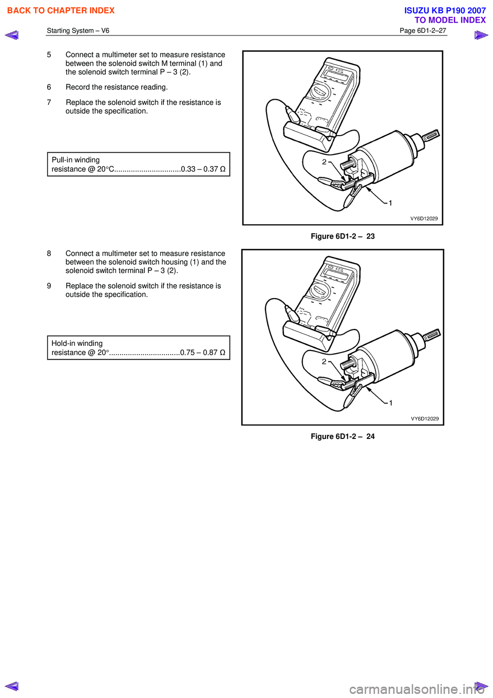
5 Connect a multimeter set to measure resistance
between the solenoid switch M terminal (1) and
the solenoid switch terminal P – 3 (2).
6 Record the resistance reading.
7 Replace the solenoid switch if the resistance is outside the specification.
Pull-in winding
resistance @ 20 °C................................0.33 – 0.37 Ω
Figure 6D1-2 – 23
8 Connect a multimeter set to measure resistance between the solenoid switch housing (1) and the
solenoid switch terminal P – 3 (2).
9 Replace the solenoid switch if the resistance is outside the specification.
Hold-in winding
resistance @ 20 °..................................0.75 – 0.87 Ω
Figure 6D1-2 – 24
BACK TO CHAPTER INDEX
TO MODEL INDEX
ISUZU KB P190 2007
Page 3636 of 6020
Starting System – V6 Page 6D1-2–28
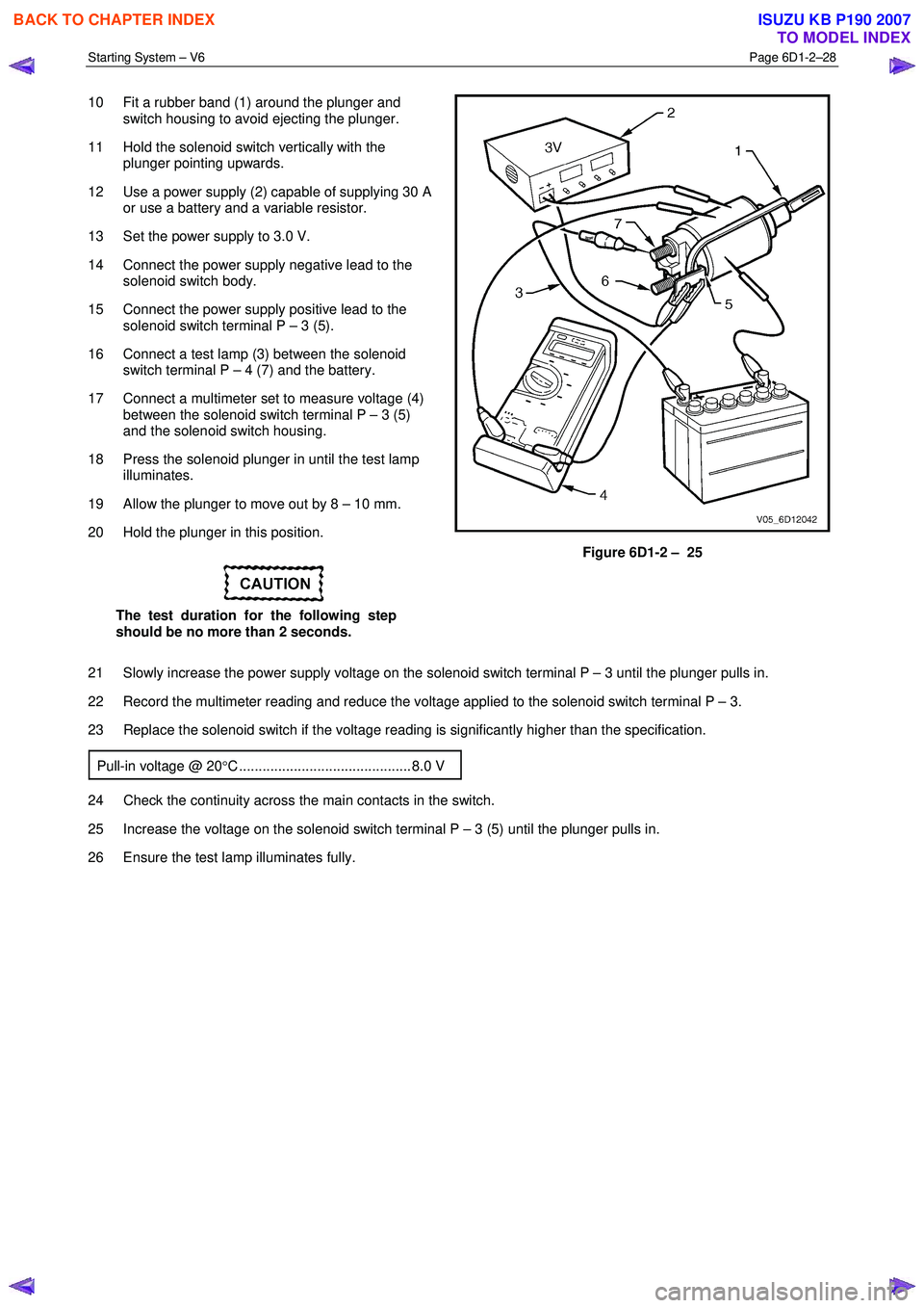
10 Fit a rubber band (1) around the plunger and
switch housing to avoid ejecting the plunger.
11 Hold the solenoid switch vertically with the plunger pointing upwards.
12 Use a power supply (2) capable of supplying 30 A or use a battery and a variable resistor.
13 Set the power supply to 3.0 V.
14 Connect the power supply negative lead to the solenoid switch body.
15 Connect the power supply positive lead to the solenoid switch terminal P – 3 (5).
16 Connect a test lamp (3) between the solenoid switch terminal P – 4 (7) and the battery.
17 Connect a multimeter set to measure voltage (4) between the solenoid switch terminal P – 3 (5)
and the solenoid switch housing.
18 Press the solenoid plunger in until the test lamp illuminates.
19 Allow the plunger to move out by 8 – 10 mm.
20 Hold the plunger in this position.
The test duration for the following step
should be no more than 2 seconds.
Figure 6D1-2 – 25
21 Slowly increase the power supply voltage on the solenoid switch terminal P – 3 until the plunger pulls in.
22 Record the multimeter reading and reduce the voltage applied to the solenoid switch terminal P – 3.
23 Replace the solenoid switch if the voltage reading is significantly higher than the specification.
Pull-in voltage @ 20 °C ............................................ 8.0 V
24 Check the continuity across the main contacts in the switch.
25 Increase the voltage on the solenoid switch terminal P – 3 (5) until the plunger pulls in.
26 Ensure the test lamp illuminates fully.
BACK TO CHAPTER INDEX
TO MODEL INDEX
ISUZU KB P190 2007
Page 3637 of 6020

Starting System – V6 Page 6D1-2–29
27 Replace the solenoid switch if the test lamp
illuminates poorly.
28 Set the power supply to 12 V (1).
29 Connect the power supply positive lead to the solenoid switch terminal P – 3 (2).
30 Connect the power supply negative lead to the solenoid switch housing (3).
31 Press the plunger in fully.
32 Release the plunger. The hold-in winding should hold the plunger in.
33 Replace the solenoid switch if the winding does not hold the plunger in.
34 Decrease the voltage until the plunger releases.
35 Record the multimeter reading.
36 Replace the solenoid switch if the voltage reading is significantly higher than the
specification.
Hold-in voltage @ 20 °C..........................1.7 – 3.0 V
37 Connect a test lamp between the solenoid
switch terminal P – 4 and the 12 volt power
supply.
38 Press the plunger in until the test lamp illuminates.
39 Attempt to press the plunger into the solenoid switch housing a further 1 mm.
40 Replace the solenoid switch if the plunger cannot move at least a further 1 mm.
Figure 6D1-2 – 26
41 Connect the positive lead of a 24 volt power supply (1) to the positive lead of a multimeter set
to measure voltage.
42 Connect the negative lead of a 24 volt power supply to the solenoid switch housing (2).
43 Connect the multimeter negative lead to the solenoid switch terminal P – 4 (3).
44 Press the plunger (4) in fully.
45 Release the plunger. The plunger should return to its rest position.
46 Replace the solenoid switch if the plunger does not return.
NOTE
This indicates the windings have an
internal winding short circuit. When the
solenoid switch is connected in this way,
the winding fields are in opposition to each
other.
Figure 6D1-2 – 27
BACK TO CHAPTER INDEX
TO MODEL INDEX
ISUZU KB P190 2007
Page 3638 of 6020
Starting System – V6 Page 6D1-2–30
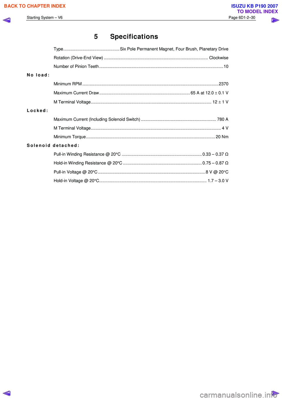
5 Specifications
Type............................................... Six Pole Permanent Magnet, Four Brush, Planetary Drive
Rotation (Drive-End View) ....................................................................................... Clockwise
Number of Pinion Teeth ........................................................................................................ 1 0
No load:
Minimum RPM .................................................................................................................. 23 70
Maximum Current Draw ............................................................................ 65 A at 12.0 ± 0.1 V
M Terminal Voltage..................................................................................................... 12 ± 1 V
Locked:
Maximum Current (Including Solenoid Switch) ............................................................... 780 A
M Terminal Voltage............................................................................................................. 4 V
Minimum Torque ............................................................................................................ 20 Nm
Solenoid detached:
Pull-in Winding Resistance @ 20°C ................................................................... 0.33 – 0.37 Ω
Hold-in Winding Resistance @ 20°C .................................................................. 0.75 – 0.87 Ω
Pull-in Voltage @ 20°C .......................................................................................... 8 V @ 20 °C
Hold-in Voltage @ 20°C.......................................................................................... 1.7 – 3.0 V
BACK TO CHAPTER INDEX
TO MODEL INDEX
ISUZU KB P190 2007
Page 3639 of 6020

Starting System – V6 Page 6D1-2–31
6 Torque Wrench Specifications
..................................................................................................................... Nm
Solenoid Switch Mounting Screw ........................................................ 4.1 – 7.6
Solenoid Switch Terminal M Nut ................................................................ 10.0
Solenoid Switch Terminal P – 3 Nut ........................................................... 10.0
Starter Motor Mounting Bolt........................................................................ 45.0
Knock Sensor Bolt ................................................................................ 23.0 Nm
Starter Motor Heat Shield Lower Bolt ................................................... 23.0 Nm
Starter Motor Heat Shield Upper Screw ........................................ 3.0 – 5.0 Nm
BACK TO CHAPTER INDEX
TO MODEL INDEX
ISUZU KB P190 2007
Page 3640 of 6020

Starting System – V6 Page 6D1-2–32
7 Special Tools
Tool Number Illustration Description Tool Classification
KM609
Connector Test Adaptor Kit
Used when carrying out electrical
diagnostic circuit checks.
Previously released
Desirable
3588
(J39200)
Digital Multimeter
Must have at least 10 M Ω input
impedance and be capable of reading
frequencies.
Previously released.
Available
EN – 46114 Engine Lifting Brackets
Available
BACK TO CHAPTER INDEX
TO MODEL INDEX
ISUZU KB P190 2007