sensor ISUZU KB P190 2007 Workshop Repair Manual
[x] Cancel search | Manufacturer: ISUZU, Model Year: 2007, Model line: KB P190, Model: ISUZU KB P190 2007Pages: 6020, PDF Size: 70.23 MB
Page 3839 of 6020
Automatic Transmission – 4L60E – Electrical Diagnosis Page 7C2–53
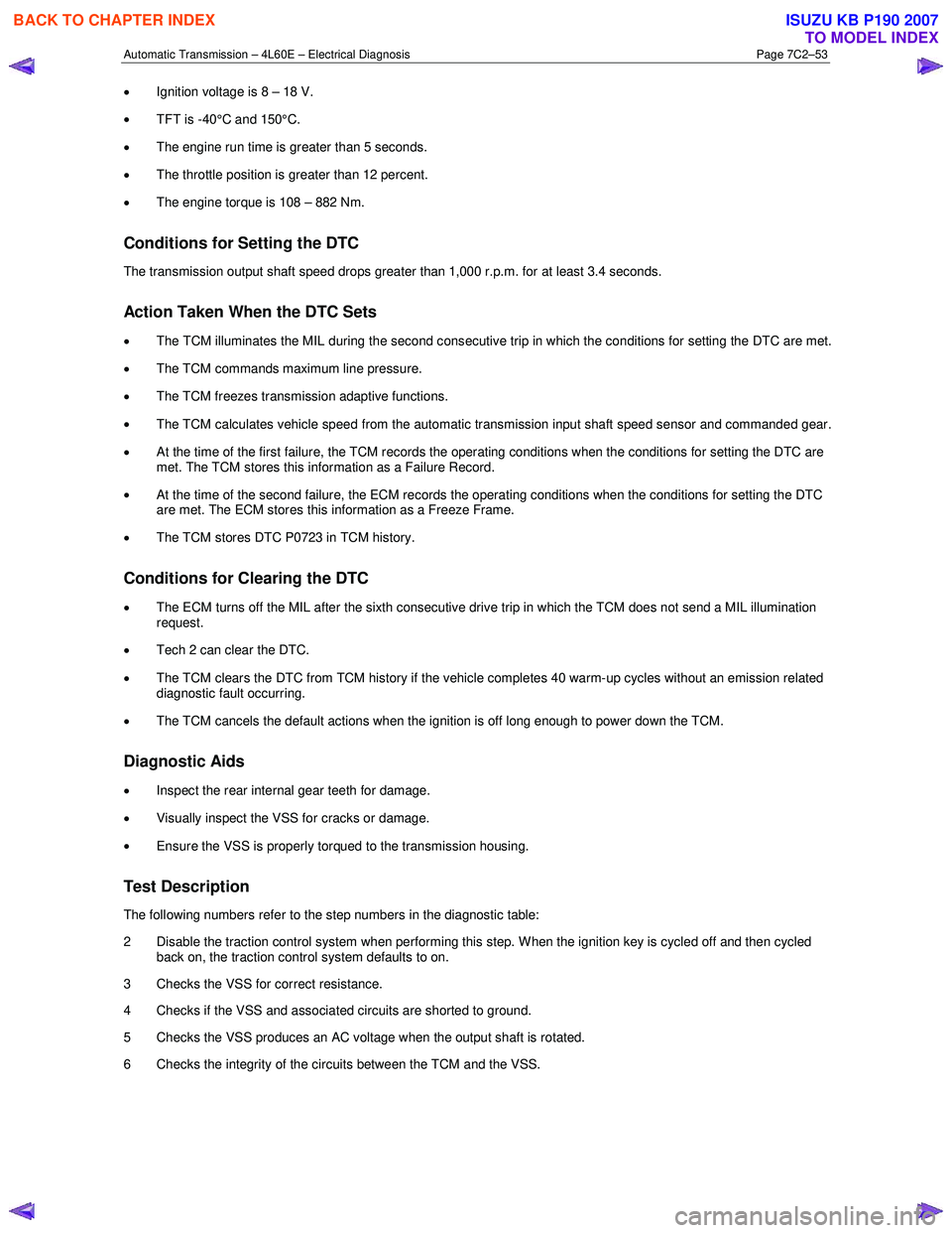
• Ignition voltage is 8 – 18 V.
• TFT is -40°C and 150°C.
• The engine run time is greater than 5 seconds.
• The throttle position is greater than 12 percent.
• The engine torque is 108 – 882 Nm.
Conditions for Setting the DTC
The transmission output shaft speed drops greater than 1,000 r.p.m. for at least 3.4 seconds.
Action Taken When the DTC Sets
• The TCM illuminates the MIL during the second consecutive trip in which the conditions for setting the DTC are met.
• The TCM commands maximum line pressure.
• The TCM freezes transmission adaptive functions.
• The TCM calculates vehicle speed from the automatic transmission input shaft speed sensor and commanded gear.
• At the time of the first failure, the TCM records the operating conditions when the conditions for setting the DTC are
met. The TCM stores this information as a Failure Record.
• At the time of the second failure, the ECM records the operating conditions when the conditions for setting the DTC
are met. The ECM stores this information as a Freeze Frame.
• The TCM stores DTC P0723 in TCM history.
Conditions for Clearing the DTC
• The ECM turns off the MIL after the sixth consecutive drive trip in which the TCM does not send a MIL illumination
request.
• Tech 2 can clear the DTC.
• The TCM clears the DTC from TCM history if the vehicle completes 40 warm-up cycles without an emission related
diagnostic fault occurring.
• The TCM cancels the default actions when the ignition is off long enough to power down the TCM.
Diagnostic Aids
•
Inspect the rear internal gear teeth for damage.
• Visually inspect the VSS for cracks or damage.
• Ensure the VSS is properly torqued to the transmission housing.
Test Description
The following numbers refer to the step numbers in the diagnostic table:
2 Disable the traction control system when performing this step. W hen the ignition key is cycled off and then cycled back on, the traction control system defaults to on.
3 Checks the VSS for correct resistance.
4 Checks if the VSS and associated circuits are shorted to ground.
5 Checks the VSS produces an AC voltage when the output shaft is rotated.
6 Checks the integrity of the circuits between the TCM and the VSS.
BACK TO CHAPTER INDEX
TO MODEL INDEX
ISUZU KB P190 2007
Page 3840 of 6020
Automatic Transmission – 4L60E – Electrical Diagnosis Page 7C2–54
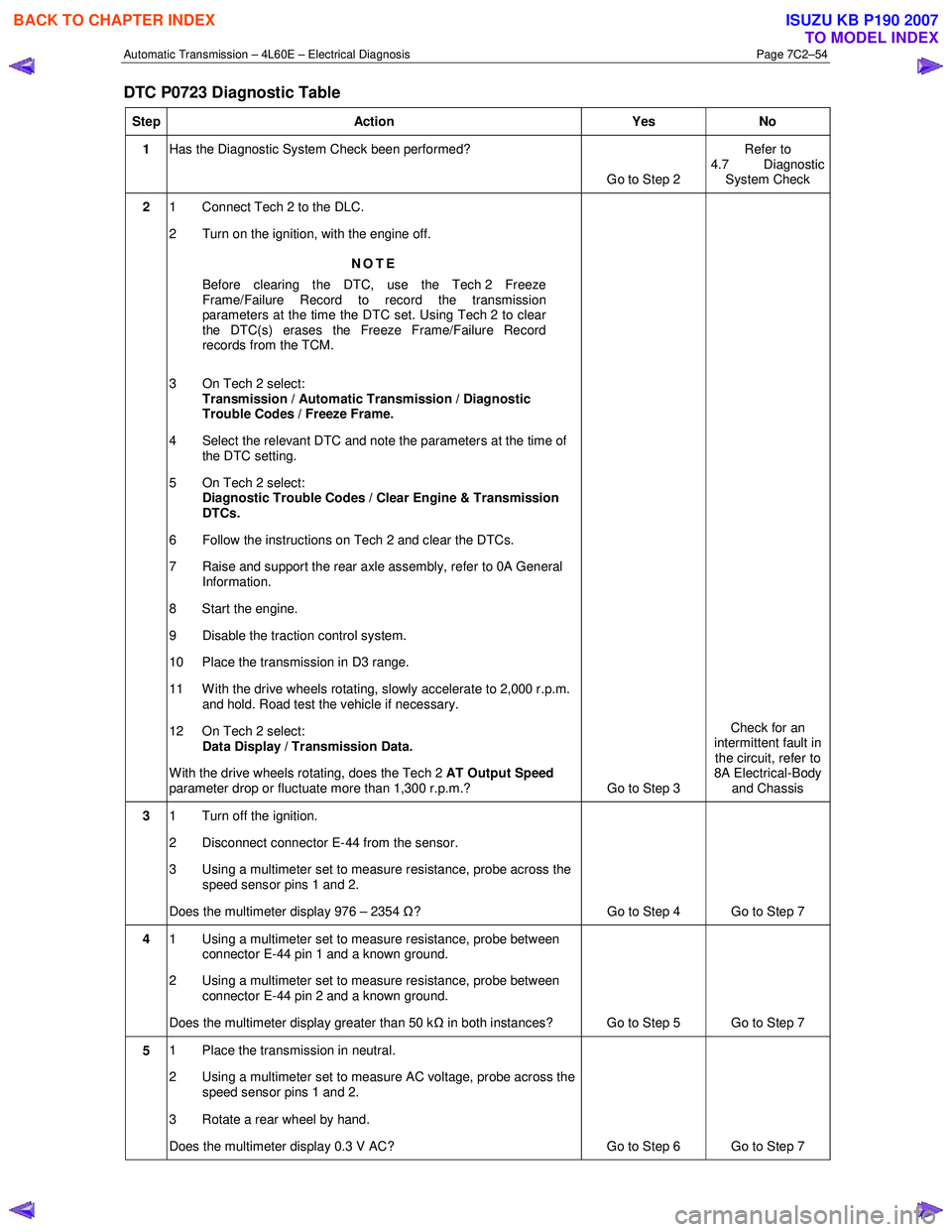
DTC P0723 Diagnostic Table
Step Action Yes No
1 Has the Diagnostic System Check been performed?
Go to Step 2 Refer to
4.7 Diagnostic System Check
2 1 Connect Tech 2 to the DLC.
2 Turn on the ignition, with the engine off.
NOTE
Before clearing the DTC, use the Tech 2 Freeze
Frame/Failure Record to record the transmission
parameters at the time the DTC set. Using Tech 2 to clear
the DTC(s) erases the Freeze Frame/Failure Record
records from the TCM.
3 On Tech 2 select: Transmission / Automatic Transmission / Diagnostic
Trouble Codes / Freeze Frame.
4 Select the relevant DTC and note the parameters at the time of the DTC setting.
5 On Tech 2 select:
Diagnostic Trouble Codes / Clear Engine & Transmission
DTCs.
6 Follow the instructions on Tech 2 and clear the DTCs.
7 Raise and support the rear axle assembly, refer to 0A General Information.
8 Start the engine.
9 Disable the traction control system.
10 Place the transmission in D3 range.
11 With the drive wheels rotating, slowly accelerate to 2,000 r.p.m. and hold. Road test the vehicle if necessary.
12 On Tech 2 select: Data Display / Transmission Data.
W ith the drive wheels rotating, does the Tech 2 AT Output Speed
parameter drop or fluctuate more than 1,300 r.p.m.? Go to Step 3 Check for an
intermittent fault in the circuit, refer to
8A Electrical-Body and Chassis
3 1 Turn off the ignition.
2 Disconnect connector E-44 from the sensor.
3 Using a multimeter set to measure resistance, probe across the speed sensor pins 1 and 2.
Does the multimeter display 976 – 2354 Ω? Go to Step 4 Go to Step 7
4 1 Using a multimeter set to measure resistance, probe between
connector E-44 pin 1 and a known ground.
2 Using a multimeter set to measure resistance, probe between connector E-44 pin 2 and a known ground.
Does the multimeter display greater than 50 k Ω in both instances? Go to Step 5 Go to Step 7
5 1 Place the transmission in neutral.
2 Using a multimeter set to measure AC voltage, probe across the speed sensor pins 1 and 2.
3 Rotate a rear wheel by hand.
Does the multimeter display 0.3 V AC? Go to Step 6 Go to Step 7
BACK TO CHAPTER INDEX
TO MODEL INDEX
ISUZU KB P190 2007
Page 3841 of 6020

Automatic Transmission – 4L60E – Electrical Diagnosis Page 7C2–55
Step Action Yes No
6 1 Disconnect connector C-96 from the TCM.
2 Test circuits speed sensor circuits (between C-96 pin 16 and E-44 pin 2; C-96 pin 41 and E-44 pin 1) for the following
conditions:
• Short to ground,
• Short to battery,
• Open circuit, and
• Short together.
Did you find and correct the condition? Go to Step 9 Go to Step 8
7 Replace the vehicle speed sensor, refer to 7C4 Automatic
Transmission – 4L60E – On-vehicle Service.
Did you complete the replacement? Go to Step 9 —
8 Replace the TCM, refer to 7C4 Automatic Transmission – 4L60E –
On-vehicle Service.
Did you complete the replacement? Go to Step 9 —
9 Perform the following procedure to verify the repair:
1 On Tech 2 select: Diagnostic Trouble Codes / Clear Engine & Transmission
DTCs.
2 Follow the instructions on Tech 2 and clear any DTCs.
3 On Tech 2 select: Data Display / Transmission Data.
4 Operate the vehicle ensuring the transmission output speed drop is less than 500 r.p.m. for 2 seconds and output speed is
greater than 500 r.p.m.
5 On Tech 2 select:
Diagnostic Trouble Codes / Read DTC Information.
Has DTC P0723 set? Go to Step 2 Go to Step 10
10 On Tech 2 select:
Diagnostic Trouble Codes / Read DTC Information.
Does Tech 2 display any DTCs you have not diagnosed? Refer to
4.8 Diagnostic Trouble Code List System OK
When all diagnosis and repairs are completed, check the system for correct operation.
4.17 DTC P0724 – Brake Switch Circuit Low
Input (Stuck Off)
DTC Description
This diagnostic procedure supports DTC P0724 Brake Switch Circuit Low Voltage.
Circuit Description
The transmission control module receives a direct input from the stop lamp switch assembly. When the brake pedal is
pressed, 12 V is supplied to the TCM through connector C-96 pin 42.
When the TCM detects an open or short to ground on the stop lamp signal circuit during stopping then DTC P0724 sets.
DTC P0724 is a type C DTC.
Refer to 2 W iring Diagrams and Connector Chart to aid in diagnosis.
BACK TO CHAPTER INDEX
TO MODEL INDEX
ISUZU KB P190 2007
Page 3842 of 6020
Automatic Transmission – 4L60E – Electrical Diagnosis Page 7C2–56
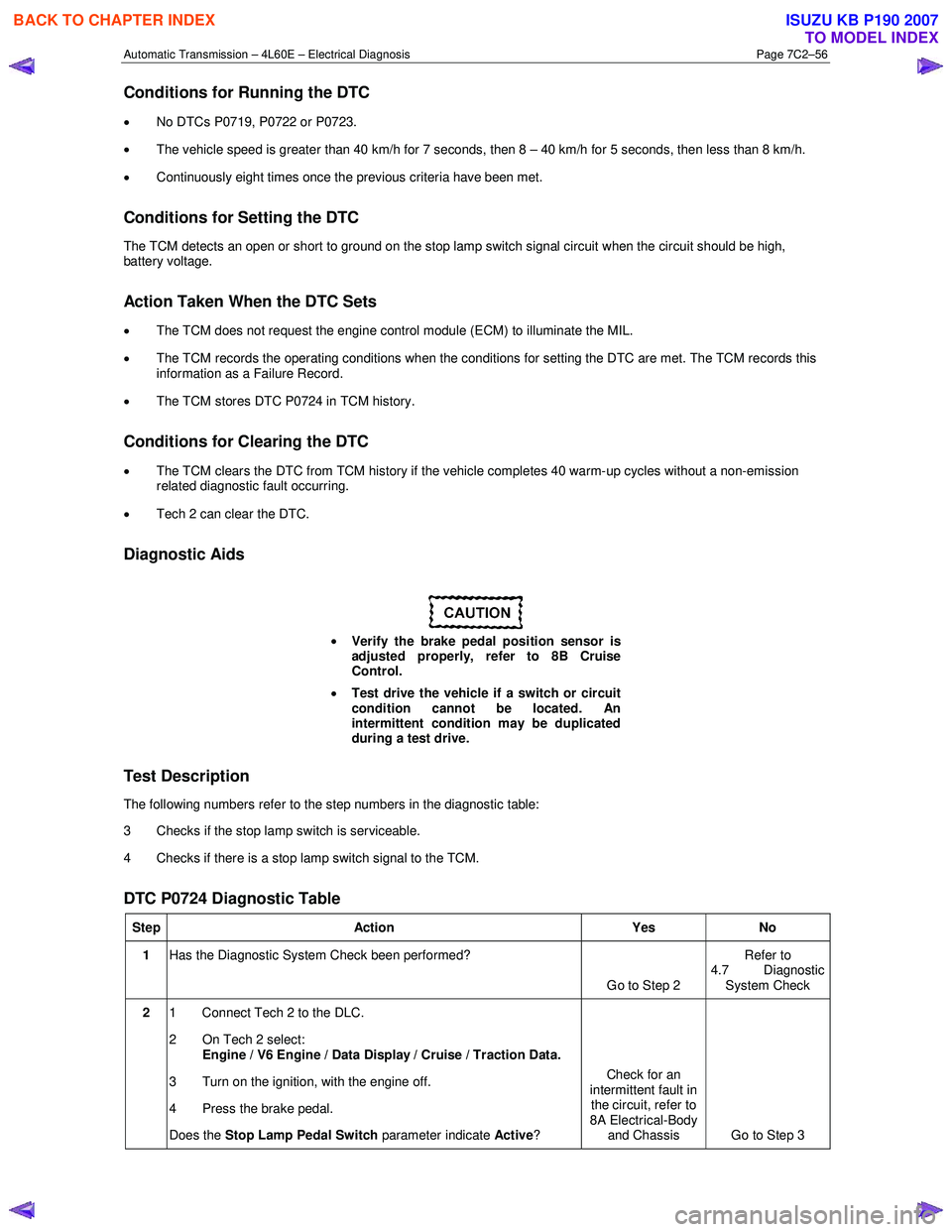
Conditions for Running the DTC
• No DTCs P0719, P0722 or P0723.
• The vehicle speed is greater than 40 km/h for 7 seconds, then 8 – 40 km/h for 5 seconds, then less than 8 km/h.
• Continuously eight times once the previous criteria have been met.
Conditions for Setting the DTC
The TCM detects an open or short to ground on the stop lamp switch signal circuit when the circuit should be high,
battery voltage.
Action Taken When the DTC Sets
• The TCM does not request the engine control module (ECM) to illuminate the MIL.
• The TCM records the operating conditions when the conditions for setting the DTC are met. The TCM records this
information as a Failure Record.
• The TCM stores DTC P0724 in TCM history.
Conditions for Clearing the DTC
•
The TCM clears the DTC from TCM history if the vehicle completes 40 warm-up cycles without a non-emission
related diagnostic fault occurring.
• Tech 2 can clear the DTC.
Diagnostic Aids
• Verify the brake pedal position sensor is
adjusted properly, refer to 8B Cruise
Control.
• Test drive the vehicle if a switch or circuit
condition cannot be located. An
intermittent condition may be duplicated
during a test drive.
Test Description
The following numbers refer to the step numbers in the diagnostic table:
3 Checks if the stop lamp switch is serviceable.
4 Checks if there is a stop lamp switch signal to the TCM.
DTC P0724 Diagnostic Table
Step Action Yes No
1 Has the Diagnostic System Check been performed?
Go to Step 2 Refer to
4.7 Diagnostic System Check
2 1 Connect Tech 2 to the DLC.
2 On Tech 2 select: Engine / V6 Engine / Data Display / Cruise / Traction Data.
3 Turn on the ignition, with the engine off.
4 Press the brake pedal.
Does the Stop Lamp Pedal Switch parameter indicate
Active? Check for an
intermittent fault in the circuit, refer to
8A Electrical-Body and Chassis Go to Step 3
BACK TO CHAPTER INDEX
TO MODEL INDEX
ISUZU KB P190 2007
Page 3889 of 6020

Automatic Transmission – 4L60E – Electrical Diagnosis Page 7C2–103
Step Action Yes No
6 Using a multimeter, test between E-95 pin 3 and C-96 pin 30 for a
short to voltage.
Did you find and correct the condition? Go to Step 8 Go to Step 7
7 Replace the TCM, refer to 7C4 Automatic Transmission – 4L60E –
On-vehicle Servicing
Did you complete the replacement? Go to Step 8 —
8 Perform the following procedure to verify the repair:
1 On Tech 2 select: Diagnostic Trouble Codes / Clear Engine & Transmission
DTCs.
2 Follow the instructions on Tech 2 and clear any DTCs.
3 On Tech 2 select: Data Display / 2-3 Shift Data.
4 Drive the vehicle in D4 and ensure the following conditions are met::
• The TCM commands the Shift Solenoid B On and the
Shift Solenoid B Circuit status parameter displays Okay.
• The TCM commands the Shift Solenoid B Off and the
Shift Solenoid B Circuit status parameter displays Okay.
• All conditions are met for 5 seconds.
4 On Tech 2 select:
Diagnostic Trouble Codes / Read DTC Information.
Has DTC P0977 set? Go to Step 2 Go to Step 9
9 On Tech 2 select:
Diagnostic Trouble Codes / Read DTC Information.
Does Tech 2 display any DTCs you have not diagnosed? Refer to
4.8 Diagnostic Trouble Code List System OK
When all diagnosis and repairs are completed, check the
system for correct operation.
4.32 DTC P1810, P1815 and P1816 –
Transmission Fluid Pressure Position
Switch
DTC Description
This diagnostic procedure supports the following DTCs:
• DTC P1810 Transmission Fluid Pressure (TFP) Position Switch Circuit.
• DTC P1815 Transmission Fluid Pressure (TFP) Valve Position Switch – Start in W rong Range.
• DTC P1816 Transmission Fluid Pressure (TFP) Valve Position Switch Indicates Park/Neutral (P/N) with Drive Ratio.
Circuit Description
The automatic transmission fluid pressure (TFP) manual valve position switch consists of five pressure switches
(two normally-closed and three normally-open) and a transmission fluid temperature (TFT) sensor combined into one unit.
The combined unit mounts on the valve body. The transmission control module (TCM) supplies ignition voltage for each
range signal. By grounding one or more of these circuits through various combinations of the pressure switches, the
TCM detects which manual valve position you select. The TCM compares the actual voltage combination of the switches
to a TFP manual valve position switch combination chart stored in memory.
The TFP manual valve position switch cannot distinguish between park and neutral because the monitored valve body
pressures are identical. W ith the engine off and the ignition switch on, the TFP manual valve position switch indicates
BACK TO CHAPTER INDEX
TO MODEL INDEX
ISUZU KB P190 2007
Page 3910 of 6020

Automatic Transmission – 4L60E – Electrical Diagnosis Page 7C2–124
5 Electrical Specifications
5.1 Transmission Fluid Temperature (TFT)
Sensor Specifications
Temperature Minimum Resistance Normal Resistance Maximum Resistance Signal
°C Ω Ω Ω Volts
-40 90636 100707 110778 5.00
-30 47416 52684 57952 4.78
-20 25809 28677 31545 4.34
-10 14558 16176 17794 3.89
0 8481 9423 10365 3.45
10 5104 5671 6238 3.01
20 3164 3515 3867 2.56
30 2013 2237 2461 1.80
40 1313 1459 1605 1.10
50 876 973 1070 3.25
60 600 667 734 2.88
70 420 467 514 2.56
80 299 332 365 2.24
90 217 241 265 1.70
100 159 177 195 1.42
110 119 132 145 1.15
120 89.9 99.9 109.9 0.87
130 69.1 76.8 84.5 0.60
140 53.8 59.8 65.8 0.32
150 42.5 47.2 51.9 0.00
5.2 Range Reference
Range Park Reverse Neutral 4 3 2 1
Gear 1st 2nd3rd4th1st2nd3rd1st ** 2nd 1st2nd ***
Shift
Solenoid A (1-2 Shift
Solenoid) ON* ON* ON* ON OFF OFF ON ON OFF OFF ON OFF ON OFF
Shift
Solenoid B (2-3 Shift
Solenoid) ON* ON* ON* ON ON OFF OFF ON ON OFF ON ON ON ON
2-4 Band - - - - A - A - A - - A - A
Reverse
Input Clutch - A - - - - - - - - - - - -
BACK TO CHAPTER INDEX
TO MODEL INDEX
ISUZU KB P190 2007
Page 3912 of 6020

Automatic Transmission – 4L60E – Electrical Diagnosis Page 7C2–126
5.5 Component Resistance
Component Pass/Thru Pins Resistance at 20°C Resistance at 100°C Resistance to Ground
(Case)
Shift Solenoid A (1-2
Shift Solenoid Valve) A, E 19 – 24
Ω 24 – 31 Ω Greater than 250 k Ω
Shift Solenoid B (2-3
Shift Solenoid Valve) B, E 19 – 24
Ω 24 – 31 Ω Greater than 250 k Ω
TCC Solenoid Valve T, E 21 – 26 Ω 26 – 33 Ω Greater than 250 k Ω
TCC PWM Solenoid
Valve U, E
10 – 11 Ω 13 – 15 Ω Greater than 250 k Ω
3-2 Shift Solenoid
Valve S, E 20 – 24
Ω 29 – 32 Ω Greater than 250 k Ω
Pressure Control
Solenoid Valve C, D
3 – 5 Ω 4 – 7 Ω Greater than 250 k Ω
*Transmission Fluid
Temperature (TFT) Sensor M, L
3088 – 3942 Ω 159.3 – 198.0 Ω Greater than 10 M Ω
Vehicle Speed Sensor A, B 1420Ω @ 25°C 2140 Ω @ 150°C Greater than 10 M Ω
*: The resistance of this device is necessarily temperature dependent and will therefore vary far more than any other
device. Refer to 5.1 Transmission Fluid Temperature (TFT) Sensor Specifications .
5.6 Shift Solenoid Valve State and Gear
Ratio
Gear 1-2 Shift Solenoid 2-3 Shift Solenoid Gear Ratio
1 ON ON 3.059:1
2 OFF ON 1.625:1
3 OFF OFF 1.000:1
4 ON OFF 0.696:1
5.7 Line Pressure
Pressure Control Solenoid Current (Amp) Approximate Line Pressure (PSI)
0.00 198 – 227
0.10 197 – 226
0.20 189 – 221
0.30 181 – 216
0.40 168 – 205
0.50 154 – 193
0.60 137 – 175
0.70 114 – 156
0.80 90 – 132
0.90 64 – 105
1.00 53 – 85
1.10 53 – 68
BACK TO CHAPTER INDEX
TO MODEL INDEX
ISUZU KB P190 2007
Page 3914 of 6020
Automatic Transmission – 4L60E – On-vehicle Servicing Page 7C4–1
7C4
Automatic Transmission – 4L60E –
On-vehicle Servicing
ATTENTION
Before performing any service operation or other procedure described in this Section, refer to General Information Warnings, Cautions and Notes for correct workshop practices with regard to safety and/or property damage.
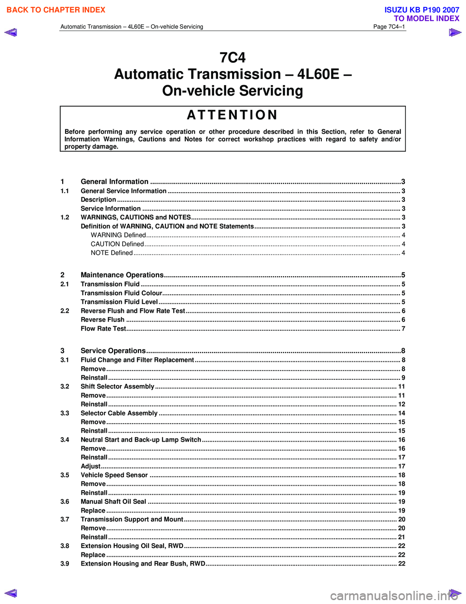
1 General Information ............................................................................................................ ...................3
1.1 General Service Information ................................................................................................................................. 3
Description ............................................................................................................................................................. 3
Service Information ............................................................................................................ ................................... 3
1.2 WARNINGS, CAUTIONS and NOTES................................................................................................... ................. 3
Definition of WARNING, CAUTION and NOTE Statements ............................................................................. .... 3
WARNING Defined............................................................................................................................................. 4
CAUTION Defined .............................................................................................................................................. 4
NOTE Defined .................................................................................................................................................... 4
2 Maintenance Operations......................................................................................................... ...............5
2.1 Transmission Fluid ................................................................................................................................................ 5
Transmission Fluid Colour...................................................................................................... .............................. 5
Transmission Fluid Level ...................................................................................................................................... 5
2.2 Reverse Flush and Flow Rate Test ............................................................................................... ........................ 6
Reverse Flush ........................................................................................................................................................ 6
Flow Rate Test........................................................................................................................................................ 7
3 Service Operations ............................................................................................................. ....................8
3.1 Fluid Change and Filter Replacement ............................................................................................ ...................... 8
Remove ................................................................................................................................................................... 8
Reinstall .................................................................................................................................................................. 9
3.2 Shift Selector Assembly ...................................................................................................................................... 11
Remove ................................................................................................................................................................. 11
Reinstall ................................................................................................................................................................ 12
3.3 Selector Cable Assembly .................................................................................................................................... 14
Remove ................................................................................................................................................................. 15
Reinstall ................................................................................................................................................................ 15
3.4 Neutral Start and Back-up Lamp Switch ............................................................................................................ 16
Remove ................................................................................................................................................................. 16
Reinstall ................................................................................................................................................................ 17
Adjust .................................................................................................................................................................... 17
3.5 Vehicle Speed Sensor ......................................................................................................................................... 18
Remove ................................................................................................................................................................. 18
Reinstall ................................................................................................................................................................ 19
3.6 Manual Shaft Oil Seal .......................................................................................................................................... 19
Replace ................................................................................................................................................................. 19
3.7 Transmission Support and Mount ................................................................................................. ..................... 20
Remove ................................................................................................................................................................. 20
Reinstall ................................................................................................................................................................ 21
3.8 Extension Housing Oil Seal, RWD ...................................................................................................................... 22
Replace ................................................................................................................................................................. 22
3.9 Extension Housing and Rear Bush, RWD ........................................................................................... ............... 22
BACK TO CHAPTER INDEX
TO MODEL INDEX
ISUZU KB P190 2007
Page 3931 of 6020
Automatic Transmission – 4L60E – On-vehicle Servicing Page 7C4–18
Ensure the four wheels are off the ground
before performing the starting test.
4 W ith the ignition switched to the ON position, check if the engine can only be started in the Park and Neutral shift selector positions and ensure the back-up lamps illuminate when Reverse is selected. A further minor adjustment
may be required to achieve this state.
NOTE
To gain access to the rear attaching screw (11) it
will be necessary to remove the connector.
5 After the switch has been adjusted, tighten the rear attaching screw (11) to the correct torque specification. Neutral start and back-up lamp switch
attaching screw torque specification .................. 25.0 Nm
6 Reinstall the connector and the CPA securing pin.
7 Remove the switch front attaching screw (1).
8 Install the heat shield (3) and tighten the attaching screws (1 and 2) to the correct torque specification.
Heat shield front attaching screw
torque specification ............................................ 25.0 Nm
Heat shield rear attaching screw torque specification ..............................................9.0 Nm
9 Lower the vehicle to the ground and re-check the operation of the neutral start and back-up lamp switch. The vehicle must start only with the shift selector in the Park or Neutral positions and the back-up lamps should only
illuminate when Reverse is selected.
3.5 Vehicle Speed Sensor
NOTE
For the speed sensor fitted to four wheel drive
vehicles (4WD), refer to 7D Transfer Case and
Adaptor Housing.
Remove
1 Raise the vehicle and support in a safe manner, refer
to 0A General Information for the location of support
points.
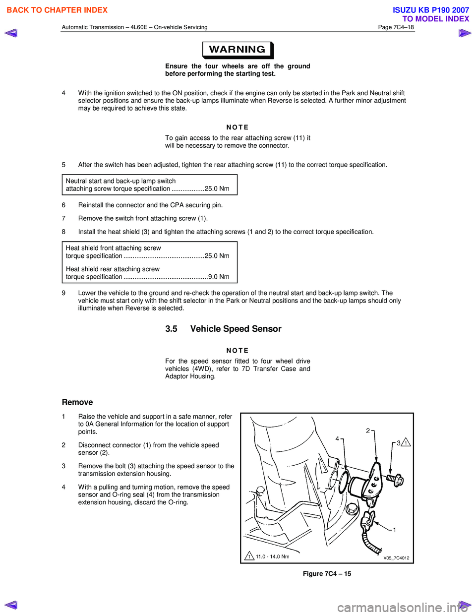
2 Disconnect connector (1) from the vehicle speed sensor (2).
3 Remove the bolt (3) attaching the speed sensor to the transmission extension housing.
4 With a pulling and turning motion, remove the speed sensor and O-ring seal (4) from the transmission
extension housing, discard the O-ring.
Figure 7C4 – 15
BACK TO CHAPTER INDEX
TO MODEL INDEX
ISUZU KB P190 2007
Page 3932 of 6020

Automatic Transmission – 4L60E – On-vehicle Servicing Page 7C4–19
Reinstall
1 Lubricate a new O-ring seal with petroleum jelly and install it to the vehicle speed sensor.
2 Install the speed sensor to the transmission extension housing.
3 Install the attaching bolt and tighten to the correct torque specification.
Vehicle speed sensor attaching bolt
torque specification ............................................ 12.0 Nm
4 Connect the connector to the speed sensor.
5 Lower the vehicle to the ground.
3.6 Manual Shaft Oil Seal
Replace
NOTE
This procedure requires the use of special tool
No. AU583.
1 Raise the vehicle and support in a safe manner, refer to 0A General Information for the location of support points.
2 Remove the neutral start and back-up lamp switch, refer to 3.4 Neutral Start and Back-up Lamp Switch.
3 Assemble the seal remover, Tool No. AU583-3 (1) by installing the remover nut, Tool No. AU583-4 (2) with
its threaded inner diameter closest to the hexagonal
head of the seal remover tool. Install the nut up to the
hexagonal head.
4 Install the assembled seal remover tool over the manual shaft (3) engaging the tapered thread end (4)
into the seal.
Do not over tighten the seal remover tool in
the seal.
5 Rotate the hexagonal head of the seal remover tool clockwise, until the thread grips the steel shell of the
seal.
Figure 7C4 – 16
6 W hile holding the hexagonal head of the seal remover tool (1) rotate the remover nut (2) clockwise, until it
contacts the transmission case.
7 Continue rotating the remover nut until the seal is pulled into the remover nut cavity.
8 Remove and discard the seal.
Figure 7C4 – 17
BACK TO CHAPTER INDEX
TO MODEL INDEX
ISUZU KB P190 2007