service ISUZU TROOPER 1995 Owners Manual
[x] Cancel search | Manufacturer: ISUZU, Model Year: 1995, Model line: TROOPER, Model: ISUZU TROOPER 1995Pages: 1928
Page 700 of 1928
6E2-4 DRIVEABILITY AND EMISSIONS
BASIC KNOWLEDGE REQUIRED
Before using this section of the Service Manual,
there are some areas that you should be familiar
with. Without this basic knowledge, you will have
trouble using the diagnostic procedures
contained in this section.
BASIC ELECTRIC CIRCUITS
You should understand the basic theory of
electricity, and know the meaning of voltage,
amps, and ohms. You should understand what
happens in a circuit with an open or a shorted
wire. You
should be able to read and understand a
wiring diagram. A shortto ground is referred to as
a ground to distinguish it from a short between
wires.
USE OF CIRCUIT TESTING TOOLS
You should know how to use a test light, how to
connect and use a tachometer, and
how to use
jumper wires to by-pass components to test
circuits. Care
should be taken to not deform the
terminal when testing.
USE OF DIGITAL VOLT-OHM METER
(DVOM)
You should be familiar with the Digital Volt-Ohm
Meter, particularly special tool J-39200 or
equivalent. You should be able to measure
voltage, resistance, and current and know how to
use the meter correctly.
The
Digital Volt-Ohm Meter is covered in the
"Special Tools" portion of this section.
DIAGNOSTIC INFORMATION
The diagnostic "Trouble Tree" charts and func
tional checks in this manual are designed to locate
a faulty circuit or component through logic based
on the process
of elimination. The charts are
prepared
with the requirement that the vehicle
functioned correctly at the time of assembly and
that there are no multiple failures.
The Engine Control Module (ECM) performs a
continual self-diagnosis on certain control
functions. This diagnostic capability is
complemented by the diagnostic procedures
contained in this
manual. The ECM's language for
communicating the source of a malfunction is a
system
of Diagnostic Trouble Codes (DTCs). The
DTC(s) are
two or three digit numbers that can
range from12 to
51. When a malfunction is
detected by the ECM, a DTC is set and the
Malfunction Indicator Lamp is illuminated.
"CHECK ENGINE" MALFUNCTION
INDICATOR
LAMP (MIL)
This light is on the instrument panel and has two
functions:
• It is used to tell the driver that a problem has
occurred, and that the
vehicle should be
taken
for service as soon as reasonably
possible.
• It
is used by the technician to read out
'Trouble Codes" to help diagnose system
problems.
As a bulb and system check, the light will come
"ON" with the key "ON" and the engine not
running. When the engine is started, the light will
turn off. If the light remains on, the self-diagnostic
system has detected a
problem. If the problem
goes away, the light will go out in most cases after
10 seconds, but a Trouble Code will remain stored
in the
ECM.
When the light remains "ON" while the engine is
running,
or when a malfunction is suspected due
to a
driveability or emissions problem, a on-board
diagnostic system check
must be performed. The
procedures
for these checks are given in Section
"A". These checks will expose malfunctions
which may
not be detected if other diagnostics
are performed
prematurely.
INTERMITTENT "CHECK ENGINE"
MALFUNCTION INDICATOR
LAMP (MIL)
In the case of an "intermittent" problem, the
"Check Engine"
malfunction indicator lamp will
light
for ten (1 0) seconds and then will go out.
However, the corresponding
trouble code will be
stored in the
memory of the ECM until the battery
positive
voltage to the ECM has been removed.
When unexpected DTC(s) appear during the
DTC
code reading process, one can assume that these
DTC(s) were set by an intermittent malfunction
and could be helpful in diagnosing the system.
An intermittent
DTC may or may not re-set. If it is
an intermittent failure, a DTC Chart is not used.
Consult the "Diagnostic Aids" on the intermittent
trouble code. Section "B" also covers the topic of
"intermittents". A physical inspection of the
applicable sub-system most often will resolve the
problem.
II
Page 702 of 1928
6E2-6 DRIVEABILITY AND EMISSIONS
FIELD SERVICE MODE
ENGINE
CONTROL MODULE (ECM)
LEARNING ABILITY
The Engine Control Module (ECM) has a
"learning"
ability which allows it to make
corrections
for minor variations in the fuel system
to improve driveability. If the battery is
disconnected to clear diagnostic codes, or for
repair, the "learning" process has to begin all over
again. A change
may be noted in the vehicle's
performance. To "teach" the vehicle, make sure
the engine is at operating temperature, and drive
at part throttle, with moderate acceleration and
idle conditions, until normal performance returns.
lfthe diagnostic test terminal is grounded with the
engine running, the system is in
"Open" or
"Closed Loop".
In "Open Loop" the "Check Engine" malfunction
indicator lamp flashes
two and one-halftimes per
seconds.
In "Closed Loop", the light flashes once per
second.
Also, in "Closed
Loop", the light will stay "OFF"
most of the time if the system is too lean. It will
stay"ON" mostofthetime if the system is too rich.
While the system is in Field Service Mode, the
ECM will be in the following diagnostic test mode:
1. New trouble codes cannot be stored in the
ECM.
2. The closed loop timer is bypassed.
STANDARD NOMENCLATURE FOR /
CERTAIN ELECTRICAL/ELECTRONIC COMPONENTS AND SYSTEMS /
Starting with the 1993 model, lsuzu Motors will be complying with the Society of Automotive ~ngineers
(SAE) Recommended Practice J 1930. J 1930 is an industry wide standard that was ad6pted into
government regulations and requires certain electrical and electronic components and
syster;ns be known
by the same
nomenclature that have the same function. This standard is also being applied to
abbreviations and acronyms.
This standard is being used in
all 1993 service publications.
To make this standard work, some names and abbreviations are being replaced
with those recommended
by the
SAE Standard. What follows is a partial listing of former ISUZU names and abbreviations besides
the
new ISUZU names and abbreviations.
Former ISUZU Name New ISUZU Name Term
3Gr
Third Gear -3GR
3rd Gear
Third Gear -3GR
4Gr
Fourth Gear -4GR
4th Gear
Fourth Gear -4GR
A/C Air Conditioning -A/C
A/C
Relay Air Conditioning Relay -A/C Relay
Absolute Presure Sensor
Manifofd Absolute Pressure Sensor -MAP Sensor
AC Air Conditioning -A/C
AC Generator . Generator -GEN
ACC Air Conditioning -A/C
Accel
Accelerator Pedal -AP
Accelerator
Accelerator Pedal -AP
ACG Generator -GEN
Air Cleaner Element(s) / Air Cleaner Filter -ACL Filter
Air Cleaner Filter Ele;nent Air Cleaner Filter -ACL Filter
Air Conditioning / Air Conditioning -A/C
Air Injection Reaction System Secondary Air Injection System -AIR System
ALDL Data Link Connector -
DLC
ALDL Diagnostic Connector DLC Diagnostic Connector -DLC Diagnostic Connector ,.
, ....
Page 708 of 1928
6E2-12 DRIVEABILITY AND EMISSIONS
L-LITER
A metric unit of capacity.
MALFUNCTION
A problem that causes the system to operate
incorrectly. Typical malfunctions are wiring harness
opens
or shorts, failed sensors or circuit components.
MAP-MANIFOLD ABSOLUTE PRESSURE
Air pressure in the intake manifold with reference to
zero or absolute vacuum.
MPH-MILE PER HOUR
A unit measuring speed needed to travel distance of
one mile (5280 feet) in one hour.
MIT -MANUAL TRANSMISSION
N.C.-NORMALLY CLOSED
State of relay contacts or solenoid plunger is close
when voltage is not applied.
N·m-NEWTON METER (Torque)
A metric unit describing force.
N.M.-NORMALLY OPEN
State of relay contacts or solenoid plung&r' is open
when voltage is applied.
NOx-NITROGEN OXIDES
One of the pullutants found in engirie exhaust.
02-0XYGEN (Sensor)
Monitors the oxygen contel)f of the exhaust system
and generates a
voltage signal to the Engine Control
Module (ECM).
OUTPUT
Result of a functi typically controlled by the ECM.
OXYGEN SE OR
Device that etects the amount of oxygen (02) in the
exhaust
stfeam. /
PCV-~OSITIVE CRANKCASE VENTILATION
Prey£nt fumes in crankcase from passing into
atmosphere.
PNP-PARK/NEUTRAL POSITION
PORT-EXHAUST OR INTAKE PORT
PWM-PULSE WIDTH MODULATE
RPM-REVOLUTION PER MINUTE
A measure of rotational speed.
SELF-DIAGNOSTIC TROl)SLE CODE
The ECM can detect malfunctions in the system. If a
malfunction occurs, the ECM turns on the malfunction
indicator lamp. A OTC can be obtained from the ECM
through the malfunction indicator lamp. This DTC will
indicate the area of the malfunction.
TACH-TACHOMETER
TB-THROTTLE BODY
TBI-THROTTLE BODY FUEL INJECTION
Computer Command Control using throttle body fuel
injection
TP SENSOR-THROTTLE POSITION SENSOR
VACUUM
Negative pressure; less than atmospheric pressure.
VIN-VEHICLE IDENTIFICATION NUMBER
VSS-VEHICLE SPEED SENSOR
Sensor which sends vehicle speed information to the
ECM.
VSV-VACUUM SWITCH VALVE
(Electronically Controlled)
VSV-VACUUM SWITCH VALVE
Temperature controlled vacuum switch, that is used to
route or exhaust vacuum at various engine
temperatures.
WOT -WIDE OPEN THROTTLE
DRIVEABILITV AND EMISSION SECTION SUMMARY
The Driveability and Emissions Sections are sub
divided into three sub sections:
SECTION A: CIRCUIT INFORMATION &
DIAGNOSIS
• Component Locations
• Wiring Diagrams
• ECM Terminal End View and Terminal
Definitions
• On-Board Diagnostic System Check. This
must be the first step of any diagnostic
procedure.
• DTC Charts with facing pages containing
circuit diagrams, circuit operation
information, and
helpful diagnostic
information.
SECTION B: DRIVEABILITY & EMISSIONS
SYMPTONS
• This sub-section assists in diagnosis of
intermittent problems or problems which
don't result in the storing of DTC(s). It is
arranged
by symptoms of poor driveability
and emissions and lists possible causes of
the problems.
SECTION C: COMPONENT CHECKS &
SERVICE
• Component and Circuit Descriptions
• On-Vehicle Service
• Functional
Checks/Diagnostic Charts
•
Page 712 of 1928
6E2-16 DRIVEABILITV AND EMISSIONS
LONG TERM (LT.) FUEL TRIM
There are from zero to seventeen different cells
which the Engine Control Module (ECM) learns at
depending on revolution per minute (rpm) and
manifold absolute pressure. This parameter
will
display what cell the ECM is using for the fuel
calculation at the time.
IDLE AIR CONTROL (lAC) COUNTS
This system is used to control engine idle speed to
the desired rpm, for different operating
conditions.
In this diagnostic test mode, the
numbers
will indicate what position the ECM
thinks the valve is in. The ECM moves the idle air
control in counts and these counts are displayed
on a
"Scan tool".
DESIRED REVOLUTION PER MINUTE
Indicates the rpm to which the ECM is trying to
control the idle.
AIR CONDITIONING (A/C) REQUEST
Displays the state of the Air Conditioning (A/C)
signal line to the ECM. Should read "YES"
whenever the A/C is requested.
AIR CONDITIONING {A/C) CLUTCH
Displays "ON" when the ECM has commanded
the
A/C Clutch "ON".
POWER STEERING PRESSURE (PSP)
SWITCH
Displays the state of switch. This reading may
vary
with the tool used and the type of switch
installed on the vehicle. The important thing is
that the reading changes state (switches) when
the steering is moved against the stops.
BA TTERV POSITIVE VOLTAGE
Displays the battery positive voltage detected at
the
ECM ignition input.
SPARK ADVANCE
This is a amount of total spark advance including
the base electronic ignition timing.
START UP ENGINE COOLANT
This parameter is the engine coolant temperature
at the
time the engine was started.
ENGINE SPEED (RPM)
RPM calculated during a crank mode, helpful in
diagnosing a NON-start condition.
FUEL TRIM ENABLE
This value is an indication when the Fuel Trim
Enable values are being updated within the ECM
program.
AIR/FUEL RATIO
This is the air to fuel ratio that is being
commanded to the injectors.
INDUCTION AIR CONTROL
The "Scan tool" will display the command being
given to the induction air control
plate system
solenoid.
SECTION B-DRIVEABILITY SYMPTOMS
Always start with Section "A" "On-Board Diagnostic
System Check" before proceeding to the driveability
symptoms.
Section "A" checks the ECM which may
cause the driveability problem. A definition
of each
symptom is included. This will then lead to the most
probable causes of the driveability problem.
SECTION C-COMPONENTS SYSTEMS
There are many component systems that are used to
control fuel and emissions. Section "C" introduces
each component system or control
with a general
description, diagnosis, and on-vehicle service.
Each
of the Section "C" diagnosis sections will contain
information on
how the "Scan tool" can be used for
diagnosing a particular component when a trouble
code has
not been set. (example: Section "C1" under
diagnosis
will explain how the "Scan tool" can be used
for diagnosis as well as what the normal readings
would be for the ECM Sensors.
•
Page 714 of 1928
6E2-18 DRIVEABILITV AND EMISSIONS
TOOLS NEEDED TO SERVICE THE SVSJEM
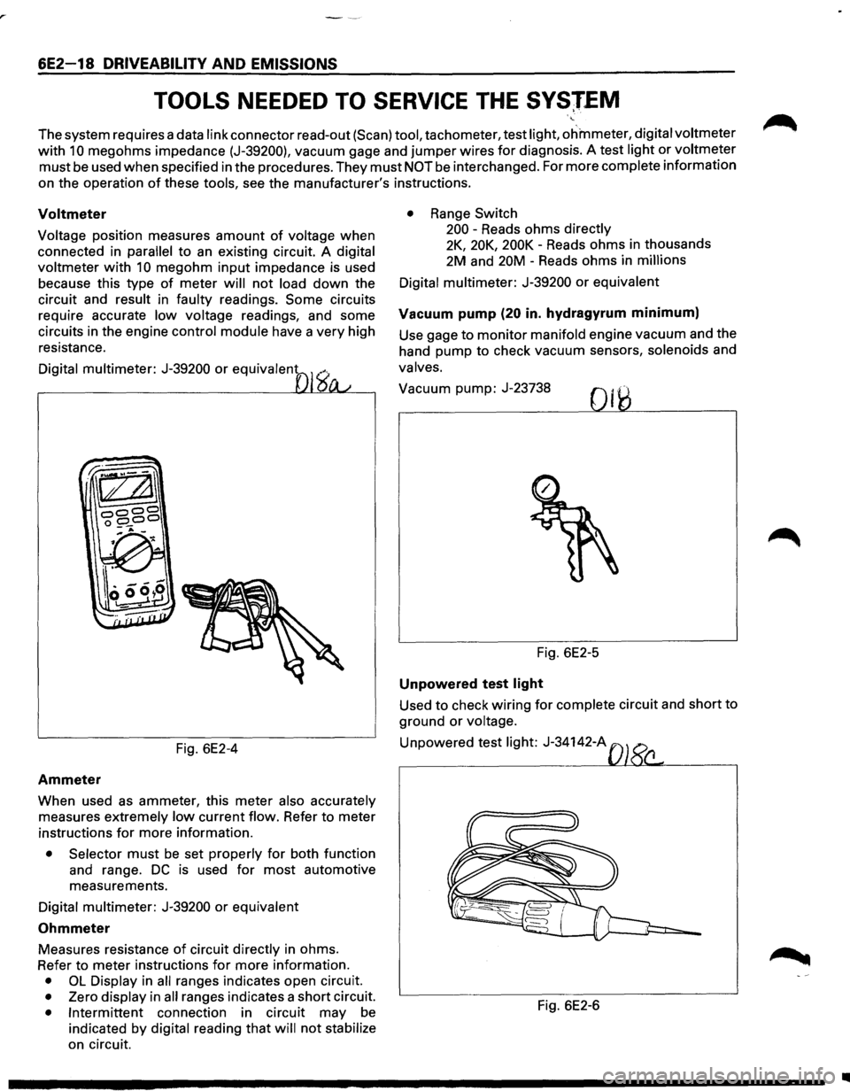
The system requires a data link connector read-out (Scan) tool, tachometer, test light, ohmmeter, digital voltmeter
with 10 megohms impedance (J-39200), vacuum gage and jumper wires for diagnosis. A test light or voltmeter
must be used when specified in the procedures. They must NOT be interchanged. For more complete information
on the operation
of these tools, see the manufacturer's instructions.
Voltmeter
Voltage position measures amount of voltage when
connected in
parallel to an existing circuit. A digital
voltmeter
with 10 megohm input impedance is used
because this type
of meter will not load down the
circuit and
result in faulty readings. Some circuits
require accurate
low voltage readings, and some
circuits in the engine
control module have a very high
resistance.
Digital multimeter: J-39200 or equivalent
Fig. 6E2-4
Ammeter
When used as ammeter, this meter also accurately
measures extremely low current flow. Refer to meter
instructions
for more information.
• Selector must be set properly for both function
and range.
DC is used for most automotive
measurements.
Digital multimeter: J-39200 or equivalent
Ohmmeter
Measures resistance of circuit directly in ohms.
Refer to meter instructions
for more information.
• OL Display in all ranges indicates open circuit.
• Zero display in all ranges indicates a short circuit.
• Intermittent connection in circuit may be
indicated by digital reading that will not stabilize
on circuit.
• Range Switch
200 -Reads ohms
directly
2K, 20K, 200K -Reads ohms in thousands
2M and 20M -Reads ohms in
millions
Digital multimeter:
J-39200 or equivalent
Vacuum pump (20 in. hydragyrum minimum)
Use gage to monitor manifold engine vacuum and the
hand pump to check vacuum sensors,
solenoids and
valves.
Vacuum pump: J-23738
Fig. 6E2-5
Unpowered test light
Used to check wiring for complete circuit and short to
ground
or voltage.
Unpowered test light: J-34142-A
Fig. 6E2-6
•
Page 717 of 1928
DRIVEABILITY AND EMISSIONS 6E2-21
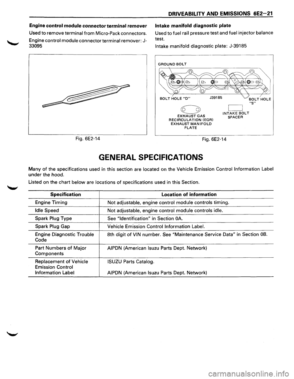
Engine control module connector terminal remover Intake manifold diagnostic plate
Used to remove terminal from Micro-Pack connectors.
Engine
control module connector terminal remover: J-
33095
Used to fuel rail pressure test and fuel injector balance
test.
Fig. 6E2-14
Intake manifold diagnostic plate: J-39185
GROUND BOLT
€3 EXHAUST GAS RECIRCULATION (EGR) EXHAUST MANIFOLD PLATE
INTAKE BOLT SPACER
Fig. 6E2-14
GENERAL SPECIFICATIONS
"S''
Many of the specifications used in this section are located on the Vehicle Emission Control Information Label
under the hood.
Listed on the chart
below are locations of specifications used in this Section.
Specification Location of information
Engine Timing
Not adjustable, engine control module controls timing.
Idle Speed Not adjustable, engine control module controls idle.
Spark Plug Type See "Identification" in Section OA.
Spark Plug Gap Vehicle Emission Control Information Label.
Engine Diagnostic Trouble 8th digit of VIN number. See "Maintenance Service Data" in Section 08.
Code
Part Numbers of Major AIPDN (American lsuzu Parts Dept. Network)
Components
Replacement of Vehicle ISUZU Parts Catalog.
Emission Control
Information Label
AIPDN
(American lsuzu Parts Dept. Network)
Page 730 of 1928
6E2-34 DRIVEABILITY AND EMISSIONS
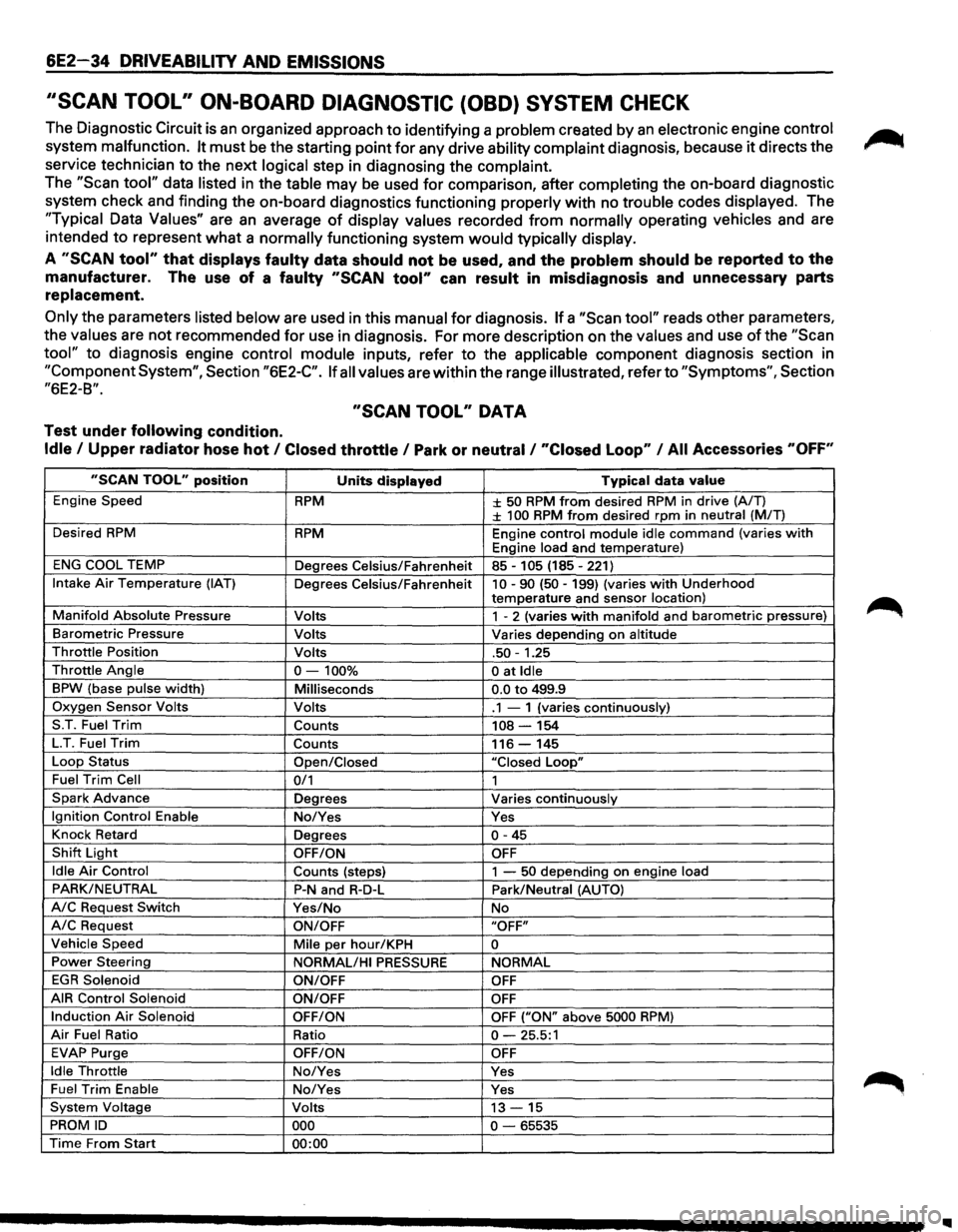
''SCAN TOOL" ON-BOARD DIAGNOSTIC (OBD) SYSTEM CHECK
The Diagnostic Circuit is an organized approach to identifying a problem created by an electronic engine control
system malfunction. It must be the starting point for any drive ability complaint diagnosis, because it directs the
service technician to the next
logical step in diagnosing the complaint.
The "Scan tool" data listed in the table may be used for comparison, after completing the on-board diagnostic
system check and finding the on-board diagnostics functioning
properly with no trouble codes displayed. The
"Typical Data Values" are an average of display values recorded from normally operating vehicles and are
intended
to represent what a normally functioning system would typically display.
A "SCAN tool" that displays faulty data should not be used, and the problem should be reported to the
manufacturer. The use of a faulty "SCAN tool" can result in misdiagnosis and unnecessary parts
replacement.
Only the parameters listed below are used in this manual for diagnosis. If a "Scan tool" reads other parameters,
the
values are not recommended for use in diagnosis. For more description on the values and use of the "Scan
tool" to diagnosis engine control module inputs, refer to the applicable component diagnosis section in
"Component System", Section "6E2-C". If all values are within the range illustrated, refer to "Symptoms", Section
"6E2-B".
"SCAN TOOL" DATA
Test under following condition.
Idle I Upper radiator hose hot I Closed throttle I Park or neutral I "Closed Loop" I All Accessories "OFF"
"SCAN TOOL" position Units displayed Typical data value
Engine Speed RPM ± 50 RPM from desired RPM in drive (A/T) ± 100 RPM from desired rpm in neutral (MIT)
Desired
RPM RPM Engine control module idle command (varies with Engine load and temperature)
ENG COOL TEMP
Degrees Celsius/Fahrenheit 85-105 (185-221)
Intake Air Temperature (IAT) Degrees Celsius/Fahrenheit 10-90 (50-199) (varies with Underhood
temperature and sensor location)
Manifold Absolute Pressure Volts 1 - 2 (varies with manifold and barometric pressure)
Barometric Pressure Volts Varies depending on altitude
Throttle Position Volts .50-1.25
Throttle Angle 0-100% 0 at Idle
BPW (base pulse width) Milliseconds 0.0 to 499.9
Oxygen Sensor Volts Volts .1 - 1 (varies continuously)
S.T. Fuel
Trim Counts 108-154
LT. Fuel Trim Counts 116-145
Loop Status
Open/Closed "Closed Loop"
Fuel Trim Cell 0/1 1
Spark Advance Degrees Varies continuously
Ignition Control Enable No/Yes Yes
Knock Retard
Degrees
0-45
Shift Light OFF/ON OFF
Idle Air Control
Counts (steps) 1 -50 depending on engine load
PARK/NEUTRAL P-N and R-D-L Park/Neutral (AUTO)
A/C Request Switch Yes/No No
A/C Request ON/OFF "OFF"
Vehicle Speed
Mile per hour/KPH 0
Power Steering
NORMAL/HI PRESSURE NORMAL
EGR Solenoid
ON/OFF OFF
AIR Control Solenoid
ON/OFF OFF
Induction Air Solenoid OFF/ON OFF ("ON" above 5000 RPM)
Air Fuel Ratio Ratio 0-25.5:1
EVAP Purge OFF/ON OFF
Idle Throttle No/Yes Yes
Fuel Trim Enable No/Yes Yes
System Voltage Volts 13-15
PROM ID 000 0-65535
Time From Start 00:00
Page 732 of 1928
6E2-36 DRIVEABILITV AND EMISSIONS
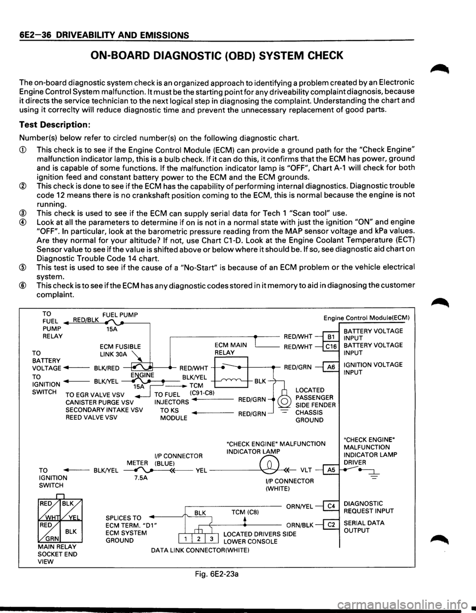
ON-BOARD DIAGNOSTIC (OBD) SYSTEM CHECK
The on-board diagnostic system check is an organized approach to identifying a problem created by an Electronic
Engine
Control System malfunction. It must be the starting point for any driveability complaint diagnosis, because
it directs the service technician to the next logical step in diagnosing the complaint. Understanding the chart and
using
it correclty will reduce diagnostic time and prevent the unnecessary replacement of good parts.
Test Description:
Number(s) below refer to circled number(s) on the following diagnostic chart.
CD This check is to see if the Engine Control Module (ECM) can provide a ground path for the "Check Engine"
malfunction indicator lamp, this is a bulb check. If it can do this, it confirms that the ECM has power, ground
and is capable
of some functions. If the malfunction indicator lamp is "OFF", Chart A-1 will check for both
ignition feed and constant battery power to the
ECM and the ECM grounds.
® This check is done to see if the ECM has the capability of performing internal diagnostics. Diagnostic trouble
code
12 means there is no crankshaft position coming to the ECM, this is normal because the engine is not
running.
® This check is used to see if the ECM can supply serial data for Tech 1 "Scan tool" use.
@ Look at all the parameters to determine if on is not in a normal state with just the ignition "ON" and engine
"OFF". In particular, look at the barometric pressure reading from the MAP sensor voltage and kPa values.
Are they normal for
your altitude? If not, use Chart C1-D. Look at the Engine Coolant Temperature (ECT)
Sensor value to see if the value is shifted above or below where it should be. If so, see diagnostic aid chart on
Diagnostic Trouble
Code 14 chart.
@ This test is used to see if the cause of a "No-Start" is because of an ECM problem or the vehicle electrical
system.
® This check is to see ifthe ECM has any diagnostic codes stored in it memory to aid in diagnosing the customer
complaint.
TO FUEL
PUMP
RELAY 15A
,------------+--RED/WHT Engine
Control Module(ECM)
BATTERY
VOLTAGE INPUT
ECM FUSIBLE L_ __ RED/WHT
~~TTERY LINK 30A ~
VOLTAGE ..,.,.f----BLK/RED
TO
~t-----tr-RED/WHT -----,t--+---.-RED/GRN
IGNITION BLK/YEL J-------BLK/YEL -TCM BLK
SWITCH
TO EGR VALVE VSV
CANISTER PURGE VSV SECONDARYINTAKEVSV REED VALVE VSV
TO FUEL (C91-C8)
INJECTORS RED/GRN
TO KS MODULE ..,._ ___ RED/GRN
LOCATED
PASSENGER
SIDE
FENDER CHASSIS
GROUND
"CHECK ENGINE" MALFUNCTION
I/P CONNECTOR INDICATOR LAMP
METER (BLUE)
f'7:' TO ..,._ __ BLK/YEL ~~VEL~(;-VLT IGNITION
SWITCH 7.5A
SPLICES TO
ECM TERM. "D1" ECM SYSTEM
GROUND
DATA LINK CONNECTOR(WHITE)
Fig. 6E2-23a
1/P CONNECTOR
(WHITE)
BATTERY VOLTAGE INPUT
IGNITION
VOLTAGE INPUT
"CHECK ENGINE"
MALFUNCTION
INDICATOR
LAMP DRIVER
-=:J._
DIAGNOSTIC
REQUEST INPUT
•
Page 747 of 1928
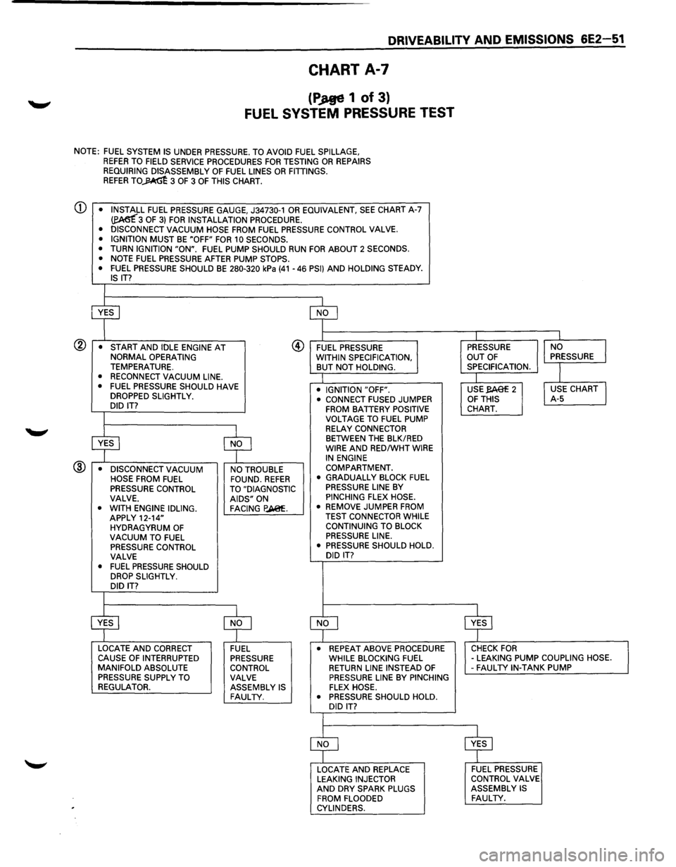
DRIVEABILITV AND EMISSIONS 6E2-51
CHART A-7
(PJtge 1 of 3}
FUEL SYSTEM PRESSURE TEST
NOTE: FUEL SYSTEM IS UNDER PRESSURE. TO AVOID FUEL SPILLAGE, REFER TO FIELD SERVICE PROCEDURES FOR TESTING OR REPAIRS
REQUIRING DISASSEMBLY OF FUEL LINES OR FITTINGS. REFER TO~ 3 OF 3 OF THIS CHART.
CD • INSTALL FUEL PRESSURE GAUGE, J34730-1 OR EQUIVALENT, SEE CHART A-7 ~3 OF 3) FOR INSTALLATION PROCEDURE.
• DISCONNECT VACUUM HOSE FROM FUEL PRESSURE CONTROL VALVE.
• IGNITION MUST BE "OFF" FOR 10 SECONDS.
• TURN IGNITION "ON". FUEL PUMP SHOULD RUN FOR ABOUT 2 SECONDS.
• NOTE FUEL PRESSURE AFTER PUMP STOPS.
• FUEL PRESSURE SHOULD BE 280-320 kPa (41-46 PSI) AND HOLDING STEADY. IS IT?
I
• START AND IDLE ENGINE AT NORMAL OPERATING TEMPERATURE. • RECONNECT VACUUM LINE.
• FUEL PRESSURE SHOULD HAVE
DROPPED SLIGHTLY.
DID IT?
I
@ FUEL PRESSURE
WITHIN SPECIFICATION,
BUT NOT HOLDING.
• IGNITION "OFF".
.---'---$YES
-$r---'--NO -
@ • DISCONNECT VACUUM NO TROUBLE •
CONNECT FUSED
JUMPER FROM BATTERY POSITIVE
VOLTAGE TO FUEL PUMP
RELAY CONNECTOR BETWEEN THE BLK/RED WIRE AND RED/WHT WIRE IN ENGINE
COMPARTMENT.
HOSE FROM
FUEL FOUND. REFER PRESSURE CONTROL TO "DIAGNOSTIC
VALVE. AIDS" ON
• WITH ENGINE IDLING. FACING P.A@f. APPLY 12-14"
HYDRAGYRUM OF VACUUM TO FUEL PRESSURE CONTROL
VALVE
•
FUEL PRESSURE SHOULD DROP SLIGHTLY.
DID IT?
I
• GRADUALLY BLOCK FUEL PRESSURE LINE BY PINCHING FLEX HOSE.
• REMOVE JUMPER FROM
TEST CONNECTOR WHILE
CONTINUING TO BLOCK
PRESSURE LINE.
• PRESSURE SHOULD HOLD.
DID
IT?
I PRESSURE
OUT OF SPECIFICATION.
I USE,.eAef 2 OF THIS CHART.
I
INO I PRESSURE
I
I USE CHART I A-5
~~NLO------------------~ $~YELS---------------------, LOCATE AND CORRECT
CAUSE OF INTERRUPTED
MANIFOLD ABSOLUTE
PRESSURE SUPPLY TO
REGULATOR. FUEL PRESSURE
CONTROL VALVE ASSEMBLY
IS FAULTY.
• REPEAT ABOVE PROCEDURE CHECK FOR WHILE BLOCKING FUEL -LEAKING PUMP COUPLING HOSE. RETURN LINE INSTEAD OF -FAUL TV IN-TANK PUMP PRESSURE LINE BY PINCHING FLEX HOSE.
• PRESSURE SHOULD HOLD.
DID
IT?
LOCATE AND REPLACE LEAKING INJECTOR AND DRY SPARK PLUGS
FROM FLOODED
CYLINDERS.
FUEL PRESSURE
CONTROL VALVE
ASSEMBLY
IS FAULTY.
Page 749 of 1928
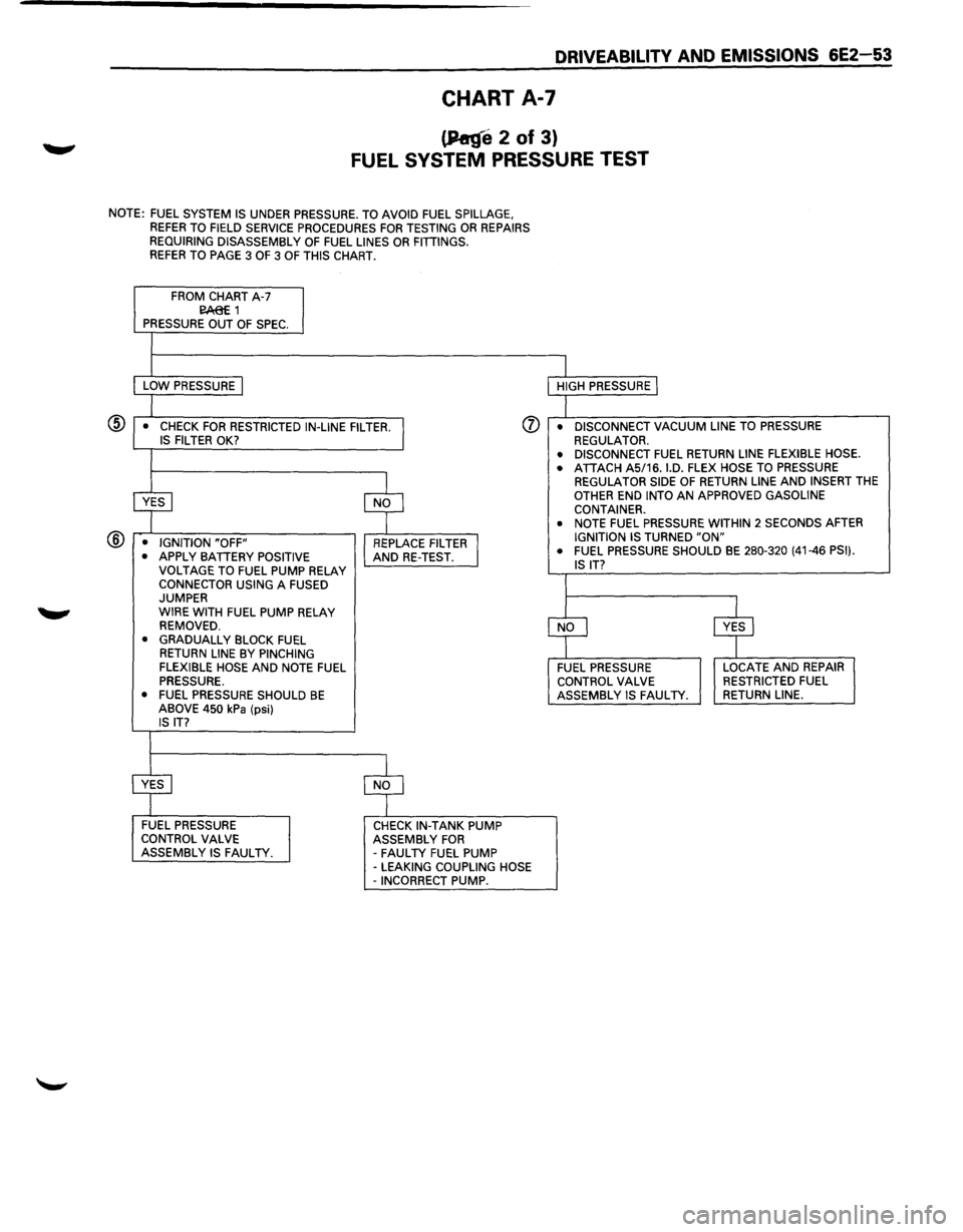
DRIVEABILITV AND EMISSIONS 6E2-53
CHART A-7
(P«ge 2 of 3)
FUEL SYSTEM PRESSURE TEST
NOTE: FUEL SYSTEM IS UNDER PRESSURE. TO AVOID FUEL SPILLAGE, REFER TO FIELD SERVICE PROCEDURES FOR TESTING OR REPAIRS
REQUIRING DISASSEMBLY OF FUEL LINES OR FITIINGS. REFER TO PAGE 3 OF 3 OF THIS CHART.
FROM CHART A-7 E!A:8E 1 PRESSURE OUT OF SPEC.
LOW PRESSURE I
(j) • CHECK FOR RESTRICTED IN-LINE FILTER. I IS FILTER OK?
® ~ $
• IGNITION "OFF"
REPLACE FILTER I • APPLY BATIERY POSITIVE AND RE-TEST.
VOLTAGE TO FUEL PUMP RELAY CONNECTOR USING A FUSED JUMPER
WIRE WITH FUEL PUMP RELAY
REMOVED.
• GRADUALLY BLOCK FUEL
RETURN LINE BY PINCHING
FLEXIBLE HOSE AND NOTE FUEL PRESSURE.
• FUEL PRESSURE SHOULD BE ABOVE 450 kPa (psi) IS IT?
~ $
FUEL PRESSURE CHECK IN-TANK PUMP
CONTROL VALVE ASSEMBLY FOR ASSEMBLY IS FAULTY.
-FAULTY FUEL PUMP -LEAKING COUPLING HOSE -INCORRECT PUMP. HIGH
PRESSURE
I
• DISCONNECT VACUUM LINE TO PRESSURE REGULATOR. • DISCONNECT FUEL RETURN LINE FLEXIBLE HOSE.
• ATIACH AS/16. I.D. FLEX HOSE TO PRESSURE REGULATOR SIDE OF RETURN LINE AND INSERT THE OTHER END INTO AN APPROVED GASOLINE
CONTAINER.
• NOTE FUEL PRESSURE WITHIN 2 SECONDS AFTER IGNITION IS TURNED "ON" • FUEL PRESSURE SHOULD BE 280-320 (41-46 PSI).
IS IT?
CfJ ~ FUEL PRESSURE LOCATE AND REPAIR
CONTROL VALVE RESTRICTED FUEL ASSEMBLY IS FAULTY. RETURN LINE.