lock ISUZU TROOPER 1995 Workshop Manual
[x] Cancel search | Manufacturer: ISUZU, Model Year: 1995, Model line: TROOPER, Model: ISUZU TROOPER 1995Pages: 1928
Page 335 of 1928
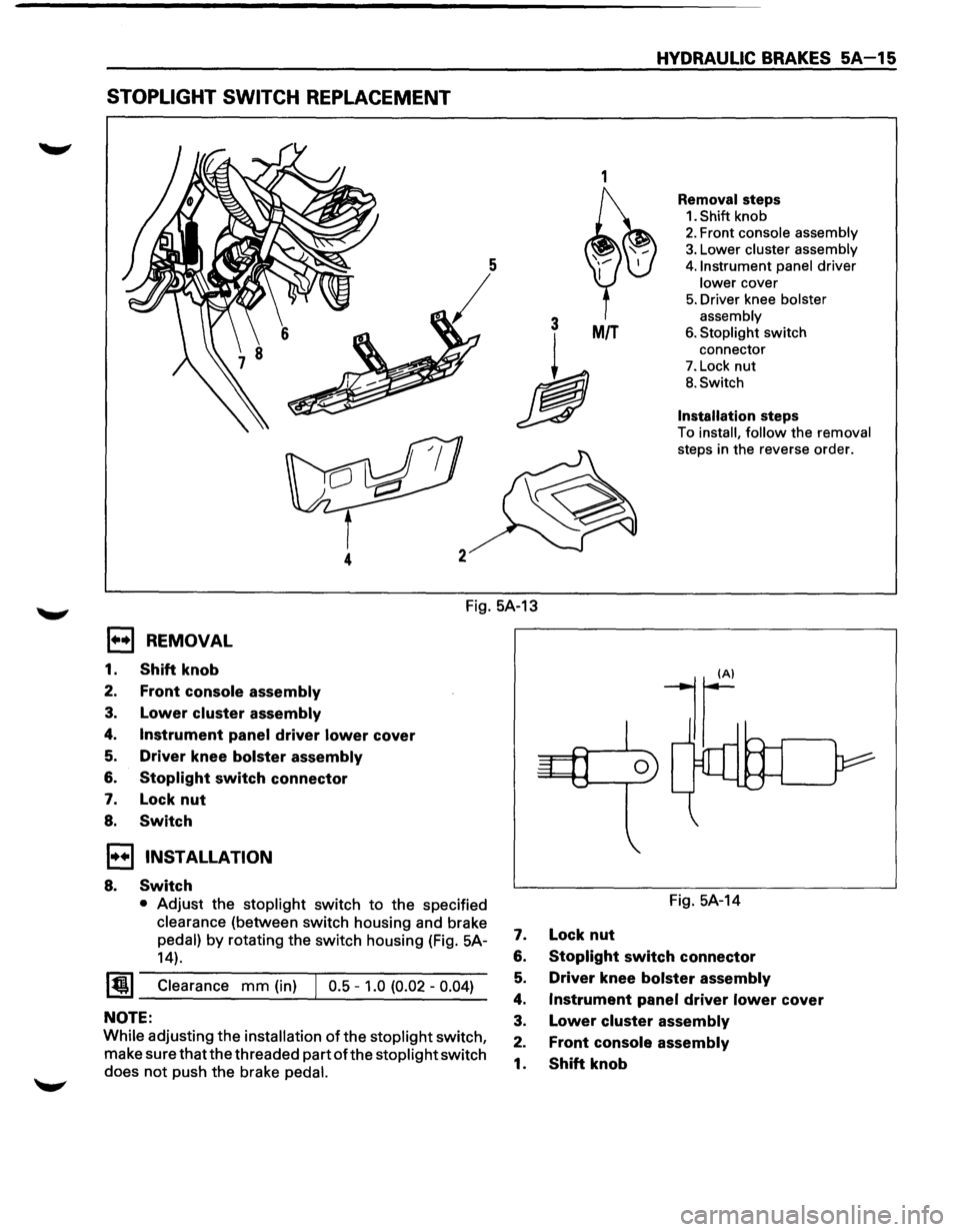
STOPLIGHT SWITCH REPLACEMENT
1
3 MIT
h
4
HYDRAULIC BRAKES SA-15
Removal steps
1. Shift knob
2. Front console assembly
3. Lower cluster assembly
4. Instrument panel driver
lower cover
5. Driver knee bolster
assembly
6. Stoplight switch
connector
7. Lock nut
B. Switch
Installation steps
To install, follow the removal
steps in the reverse order.
Fig. 5A-13
1••1 REMOVAL
1. Shift knob
2. Front console assembly
3. Lower cluster assembly
4. Instrument panel driver lower cover
5. Driver knee bolster assembly
6. Stoplight switch connector
7. Lock nut
8. Switch
1••1 INSTALLATION
8. Switch
• Adjust the stoplight switch to the specified
clearance (between switch housing and brake
pedal) by rotating the switch housing (Fig. 5A-
14).
~~~ Clearance mm (in) J 0.5 -1.0 (0.02 -0.04)
NOTE:
While adjusting the installation of the stoplight switch,
make sure that the threaded part
ofthe stoplight switch
does
not push the brake pedal.
Fig. 5A-14
7. Lock nut
6. Stoplight switch connector
5. Driver knee bolster assembly
4. Instrument panel driver lower cover
3. Lower cluster assembly
2. Front console assembly
1. Shift knob
Page 337 of 1928
HYDRAULIC BRAKES 5A-17
ON-VEHICLE SERVICE
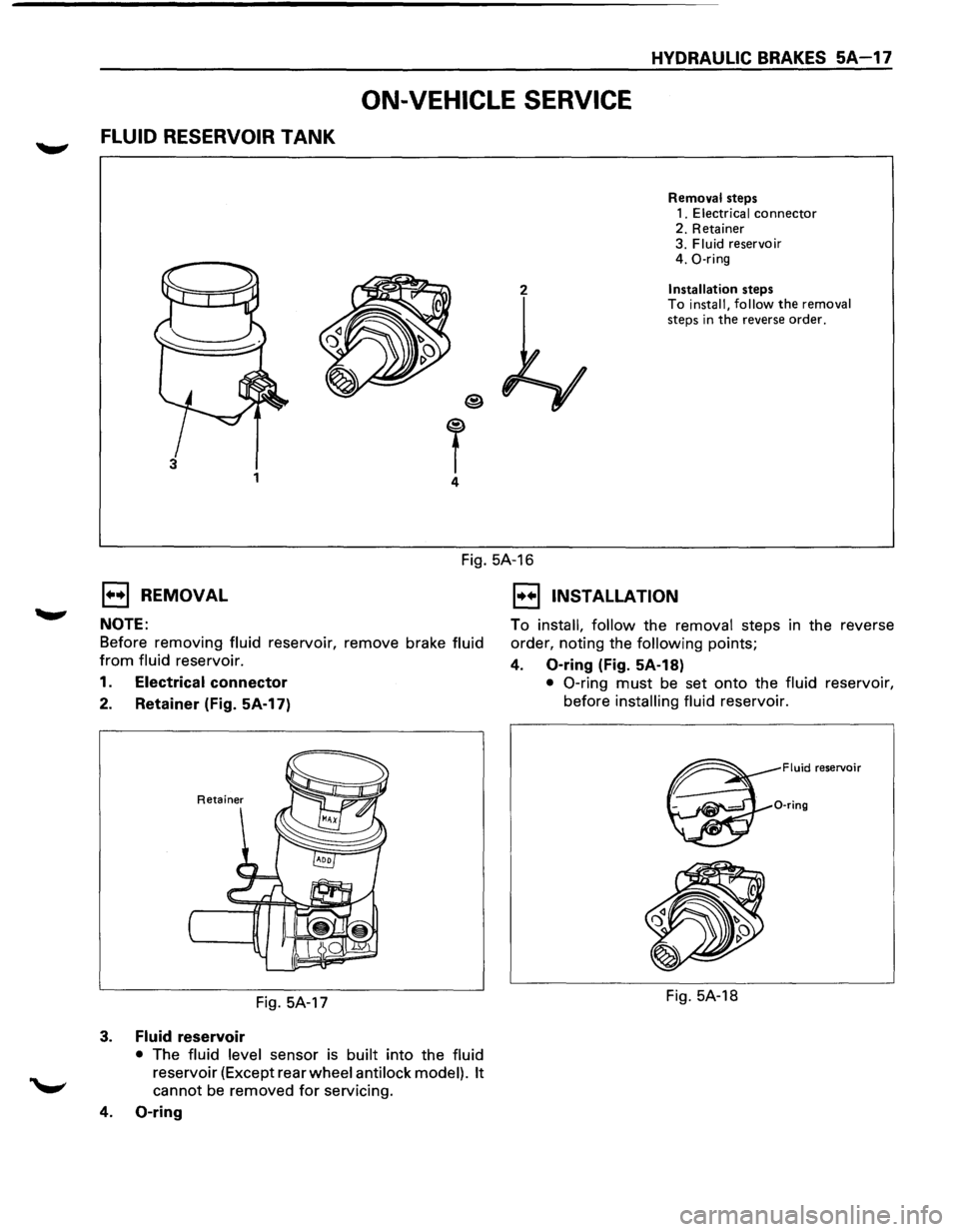
FLUID RESERVOIR TANK
2
T 4
3 1
Removal steps
1. Electrical connector 2. Retainer
3. Fluid reservoir
4. 0-ring
Installation steps
To install, follow the removal steps in the reverse order.
Fig. 5A-16
1••1 REMOVAL
NOTE:
Before removing fluid reservoir, remove brake fluid
from fluid reservoir.
1. Electrical connector
2. Retainer (Fig. 5A-17)
Fig. 5A-17
3. Fluid reservoir
• The fluid level sensor is built into the fluid
reservoir (Except rear wheel anti lock model). It
cannot be removed for servicing.
4. 0-ring
1••1 INSTALLATION
To install, follow the removal steps in the reverse
order, noting the
following points;
4. 0-ring (Fig. 5A-18)
• 0-ring must be set onto the fluid reservoir,
before
installing fluid reservoir.
Fluid reservoir
0-ring
Fig. 5A-18
Page 341 of 1928
HYDRAULIC BRAKES 5A-21
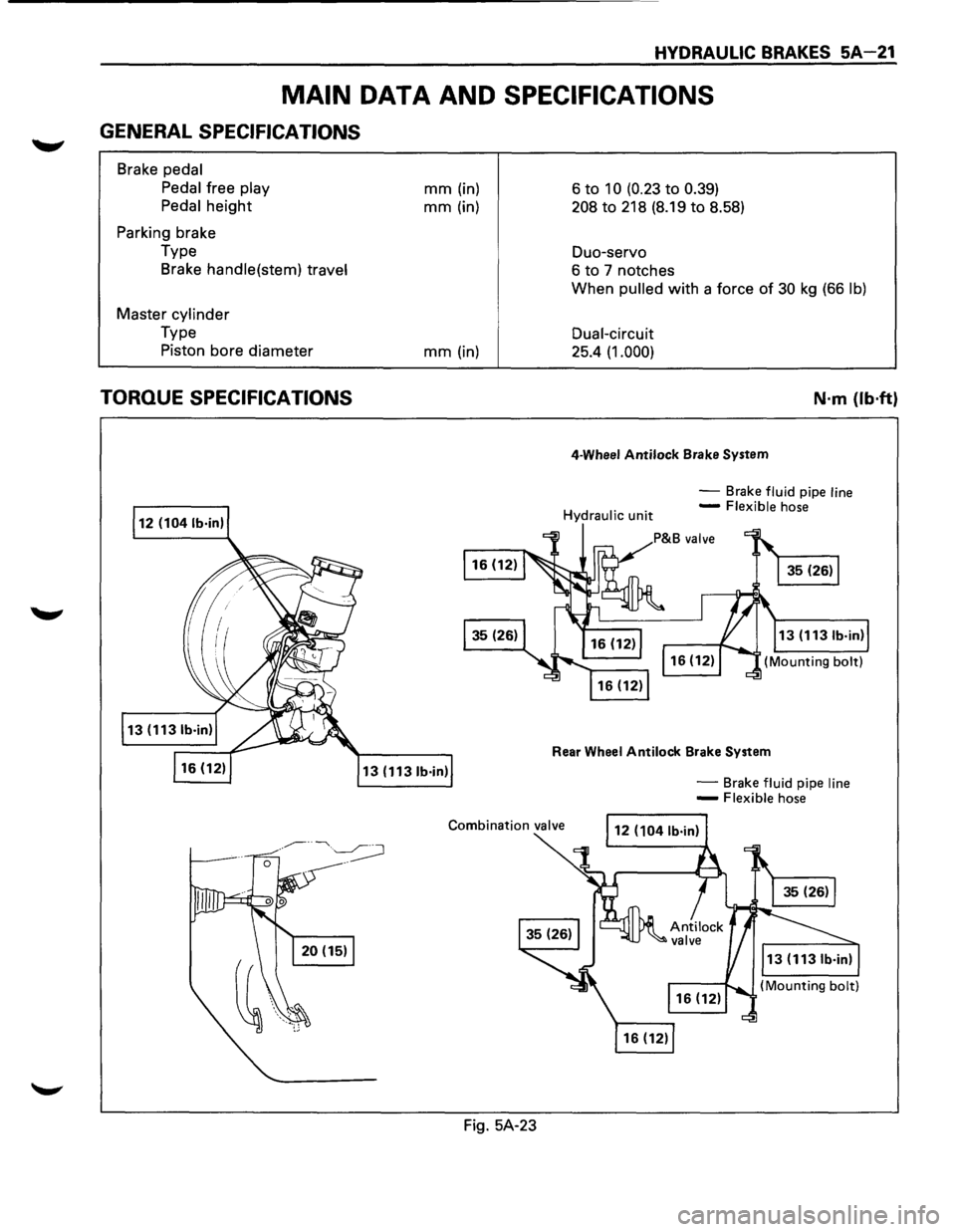
MAIN DATA AND SPECIFICATIONS
GENERAL SPECIFICATIONS
Brake pedal
Pedal
free play
Pedal
height
Parking brake
Type Brake
handle(stem) travel
Master cylinder
Type
Piston bore diameter
TORQUE SPECIFICATIONS
mm (in)
mm (in)
mm (in)
13 (1131b·in)
Fig. 5A-23 6
to 10 (0.23 to 0.39)
208 to 218
(8.19 to 8.58)
Duo-servo
6 to 7 notches
When
pulled with a force of 30 kg (66 lb)
Dual-circuit
25.4 (1.000)
4-Wheel Antilock Brake System
N·m {lb·ft}
-Brake fluid pipe line -Flexible hose
Rear Wheel Antilock Brake System
-Brake fluid pipe line -Flexible hose
Page 346 of 1928
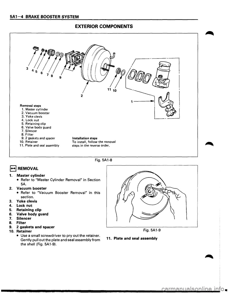
SA 1-4 EXTERI _ BRAKE BOOSTER SYSTEM OR COMPQ .• N,.=E~N~T_s ____ _
l;JJ!!
3 4 5 6 7
8 9
Removal steps. d
1 Master cylm er
2. Vacuum b.ooster
3. Yoke
clevis
4
: Lock n.ut .
5
Retainmg clip d
6: Valve body guar
7. Silencer
8. filter d spacer
9. 2 gas.kets an
10.
Retame~ seal assembly 11. Plate an
Installation s:~P.; the removal To install, fo o rse order. ·In the reve
steps
DREMOVAL
-----------FF:iigg. SA1-8-
1::1 1 • in
Section 1. Master cyl!.~::ter Cylinder Remova • Refer to
SA. t r I" in this
2 Vacuu "Vacuum m boos e Booster Remova · • Refer to
section.
Yoke
clevis 3. t Lock nu .
4. Retaining clop d
5. Valve body guar 6.
Silencer 7.
a. Filter d spacer
9 2 gaskets an tthe retainer.
1 0. Retainer a II screwdriver tol'::'a~~ssembly from • Use a sm II outthe plate an s Gently pu F' SA 1-9). the shell ( IQ.
11. Fig.
SA1-9
I assembly Plate and sea
•
Page 347 of 1928
[1!) INSPECTION AND REPAIR
Visual check:
'-"' Make necessary parts replacement if cuts, nicks,
excessive wear,
or other abnormal conditions are
found through inspection.
Check the following parts.
• Yoke clevis
• Valve
body guard
• Silencer
• Filter
• Plate
and seal assembly.
I••IINSTALLATION
11. Plate and seal assembly
1 0. Retainer
9. 2 gaskets and spacer
8. Filter
7. Silencer
6. Valve body guard
5. Retainer
4. Lock nut
20 (15) 1~1 Torque N·m (lb·ft) ----------1....---
3. Yoke clevis
2. Vacuum booster
• Refer to "Vacuum Booster Installation" in this
section.
'-"" 1. Master cylinder
• Refer to "Master Cylinder Installation" in
Section 5A.
• After installation, perform brake pedal check
and adjustment. Refer
to "Brake Pedal
Assembly" in Section 5A.
BRAKE BOOSTER SYSTEM 5A 1-5
Page 353 of 1928
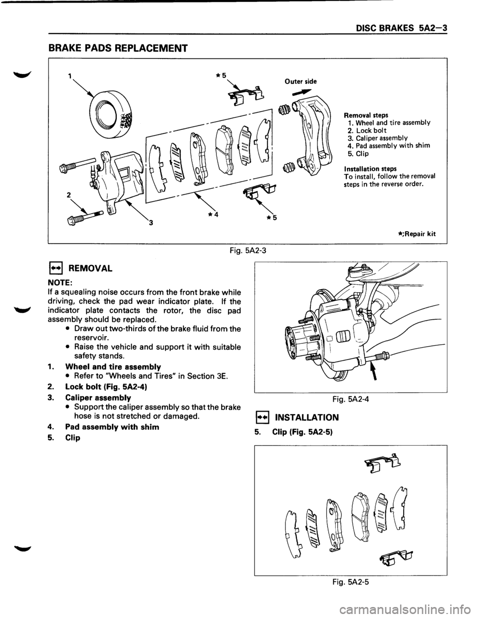
BRAKE PADS REPLACEMENT
1 Outer side
2
DISC BRAKES 5A2-3
Removal steps
1. Wheel and tire assembly
2. Lock
bolt 3. Caliper assembly
4. Pad assembly with shim
5. Clip
Installation
steps To install, follow the removal
steps in the reverse order.
*;Repair kit
Fig. 5A2-3
1••1 REMOVAL
NOTE:
If a squealing noise occurs from the front brake while
driving, check the pad wear indicator plate. If the
........., indicator plate contacts the rotor, the disc pad
assembly should be replaced.
•
Draw out two-thirds of the brake fluid from the
reservoir.
• Raise the vehicle and support it with suitable
safety stands.
1. Wheel and tire assembly
•
Refer to "Wheels and Tires" in Section 3E.
2. Lock bolt (Fig. 5A2-4)
3. Caliper assembly
• Support
the caliper assembly so that the brake
hose
is not stretched or damaged.
4. Pad assembly with shim
5. Clip
Fig. 5A2-4
1••1 INSTALLATION
5. Clip (Fig. 5A2-5)
Fig. 5A2-5
Page 354 of 1928
5A2-4 DISC BRAKES
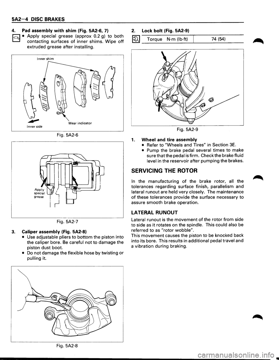
4. Pad assembly with shim (Fig. 5A2-6, 7)
1-c::~t:.l• Apply ~pecial grease (approx 0.2 g) to both
contactmg surfaces
of inner shims. Wipe off
extruded grease after installing.
Inner shim
Wear
indicator Inner side
Fig. 5A2-6
Fig. 5A2-7
3. Caliper assembly (Fig. 5A2-8)
• Use adjustable pliers to bottom the piston into
the
caliper bore. Be careful not to damage the
piston
dust boot.
• Do not damage the flexible hose by twisting or
pulling it.
Fig. 5A2-8
2. Lock bolt (Fig. 5A2-9)
1«1 Torque N·m (lb·ft) 74 (54)
Fig. 5A2-9
1. Wheel and tire assembly
• Refer to "Wheels and Tires" in Section 3E.
• Pump the brake pedal several times to make
sure that the pedal is firm. Check the brake fluid
level in the reservoir after pumping the brakes.
SERVICING THE ROTOR
In the manufacturing of the brake rotor, all the
tolerances regarding surface finish,
parallelism and
lateral
runout are held very closely. The maintenance
of these tolerances provide the surface necessary to
assure smooth brake operation.
LATERAL RUNOUT
Lateral runout is the movement of the rotor from side
to side as it rotates on the spindle. This could also be
referred
to as "rotor wobble".
This movement causes the piston to be knocked back
into its bore. This results in
additional pedal travel and
a vibration during braking.
Page 356 of 1928
5A2-8 DISC BRAKES
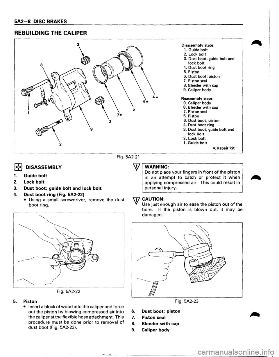
REBUILDING THE CALIPER
8
3~
'
3
7* 1
~
9
2 Disassembly
steps
1. Guide
bolt 2. Lock bolt
3. Dust boot; guide bolt and lock bolt 4. Dust boot ring
5. Piston
6. Dust
boot; piston
7. Piston
seal
8. Bleeder with cap
9. Caliper body
Reassembly steps
9.
Caliper body
8. Bleeder with cap
7. Piston seal 5. Piston
6. Dust boot; piston
4. Dust
boot ring
3. Dust boot; guide bolt and
lock bolt 2. Lock bolt 1. Guide bolt
*;Repair kit
Fig. 5A2-21
l•!•l DISASSEMBL V
1. Guide bolt
2. Lock bolt
3. Dust boot; guide bolt and lock bolt
4. Dust boot ring (Fig. 5A2-22)
• Using a small screwdriver, remove the dust
boot ring.
Fig. 5A2-22
5. Piston
• Insert a block of wood into the caliper and force
out the piston by blowing compressed air into
the
caliper at the flexible hose attachment. This
procedure
must be done prior to removal of
dust boot (Fig. 5A2-23).
WARNING:
Do not place your fingers in front of the piston
in
an attempt to catch or protect it when
applying compressed air. This could result in
personal injury.
W CAUTION:
VI Use just enough air to ease the piston out of the
bore.
If the piston is blown out, it may be
damaged.
Fig. 5A2-23
6. Dust boot; piston
7. Piston seal
8. Bleeder with cap
9. Caliper body
Page 357 of 1928
ll .. •l INSPECTION AND REPAIR
Make necessary parts replacement, if wear, damage,
"'-"' corrosion or any other abnormal conditions are found
through inspection.
Check the following parts;
• Rotor
• Cylinder body
• Cylinder bore
• Piston
•
Guide bolt, Lock bolt
•
Support bracket
NOTE:
The piston seal, boot ring and dust boot are to be
replaced each time the caliper is overhauled. Discard
these used rubber parts and
replace with new ones.
l*!•l REASSEMBLY
9. Caliper body
8. Bleeder with cap
~~~ Torque N·m (lb·in) 8 (69)
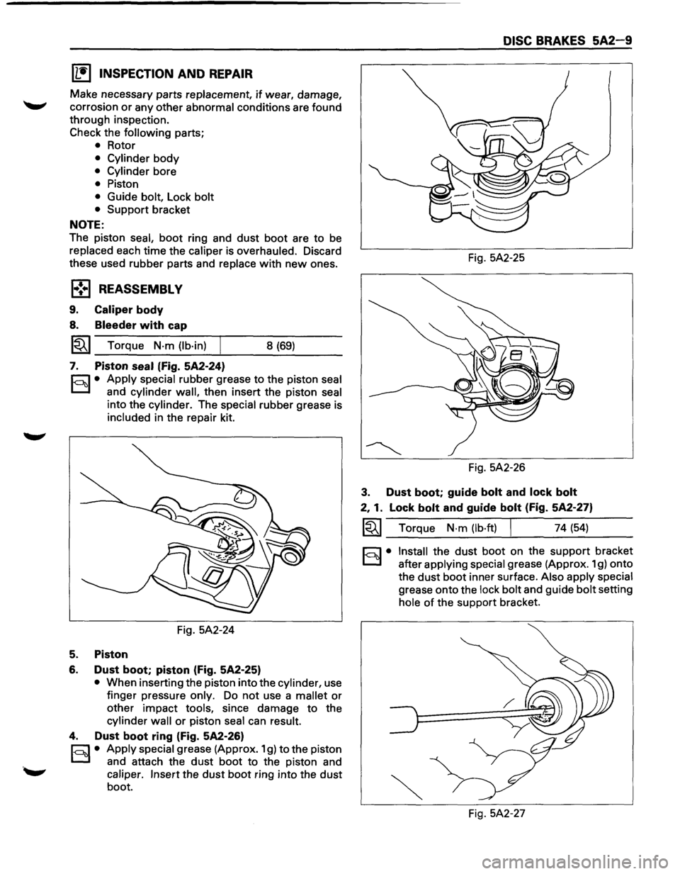
7. Piston seal (Fig. 5A2-24)
r.:;::'1 • Apply special rubber grease to the piston seal
0 and cylinder wall, then insert the piston seal
into the cylinder. The special rubber grease is
included in the repair kit.
Fig. 5A2-24
5. Piston
6. Dust boot; piston (Fig. 5A2-25)
• When inserting the piston into the cylinder, use
finger pressure
only. Do not use a mallet or
other impact tools, since damage to the
cylinder wall or piston seal can result.
4. Dust boot ring (Fig. 5A2-26)
r;::;:] • Apply special grease (Approx. 1 g) to the piston
0 and attach the dust boot to the piston and
caliper. Insert the dust boot ring into the dust
boot.
DISC BRAKES 5A2-9
Fig. 5A2-25
Fig. 5A2-26
3. Dust boot; guide bolt and lock bolt
2, 1. Lock bolt and guide bolt (Fig. 5A2-27)
~~~ Torque N·m (lb·ft) I 74 (54)
§)• Install the dust boot on the support bracket
after
applying special grease (Approx. 1 g) onto
the
dust boot inner surface. Also apply special
grease onto the lock bolt and guide bolt setting
hole of the support bracket.
Fig. 5A2-27
Page 358 of 1928
5A2-1 0 DISC BRAKES
REAR DISC BRAKE
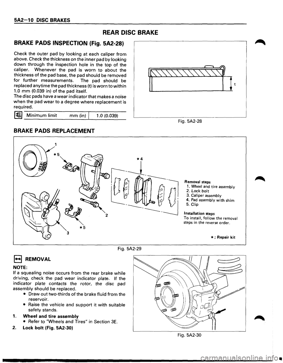
BRAKE PADS INSPECTION (Fig. 5A2-28)
Check the outer pad by looking at each caliper from
above. Check the thickness on the inner pad by looking
down through the inspection hole in the top of the
caliper. Whenever the pad is worn to about the
thickness
of the pad base, the pad should be removed
for further measurements. The pad should be
replaced anytime the pad thickness (t) is worn to within
1.0 mm (0.039 in) of the pad itself. 'f'-~1~
The disc pads have a wear indicator that makes a noise
when the pad wear to a degree where replacement is
required.
~~~-M--in-im __ u_m_l-im--it _____ m_m--(i-n)-rl--,-.-0-(0-.-03_9_) ___
BRAKE PADS REPLACEMENT
EJ REMOVAL
NOTE:
1
*5
3
Fig. 5A2-29
If a squealing noise occurs from the rear brake while
driving, check the pad wear indicator plate. If the
indicator
plate contacts the rotor, the disc pad
assembly should be replaced.
•
Draw out two-thirds of the brake fluid from the
reservoir.
• Raise the vehicle and support it with suitable
safety stands.
1. Wheel and tire assembly
•
Refer to "Wheels and Tires" in Section 3E.
2. Lock bolt (Fig. 5A2-30) Fig.
5A2-28
Removal steps
1. Wheel and tire assembly 2. Lock bolt 3. Caliper assembly
4. Pad assembly with shim 5. Clip
Installation
steps
To
install, follow the removal steps in the reverse order.
* ; Repair kit
Fig. 5A2-30
•