lock ISUZU TROOPER 1995 Manual Online
[x] Cancel search | Manufacturer: ISUZU, Model Year: 1995, Model line: TROOPER, Model: ISUZU TROOPER 1995Pages: 1928
Page 282 of 1928
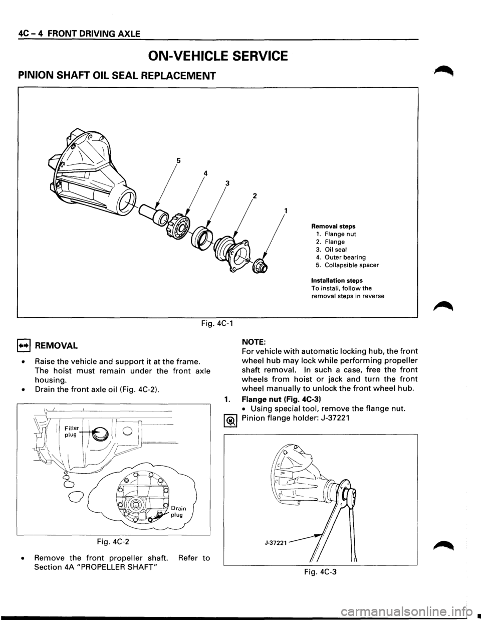
4C-4 FRONT DRIVING AXLE
ON-VEHICLE SERVICE
PINION SHAFT OIL SEAL REPLACEMENT
1
Removal steps 1. Flange nut
2. Flange 3. Oil seal 4. Outer bearing
5. Collapsible spacer
Installation steps To install, follow the removal steps in reverse
Fig. 4C-1
1••1 REMOVAL
• Raise the vehicle and support it at the frame.
The
hoist must remain under the front axle
housing.
• Drain the front axle oil (Fig. 4C-2).
~wIll ~I · I ~----fl______~~-' Filler (./ Q i,
//plug ~ I ) . ---
-\\I 11/~/~
~ <:1 0
0
0
Fig. 4C-2
•
Remove the front propeller shaft. Refer to
Section 4A "PROPELLER SHAFT"
NOTE:
For vehicle with automatic locking hub, the front
wheel hub may lock while performing propeller
shaft removal. In such a case, free the front
wheels from hoist or jack and turn the front
wheel manually to unlock the front wheel hub.
1. Flange nut (Fig. 4C-3)
• Using special tool, remove the flange nut.
1®.1 Pinion flange holder: J-37221
Fig.
4C-3
•
Page 285 of 1928
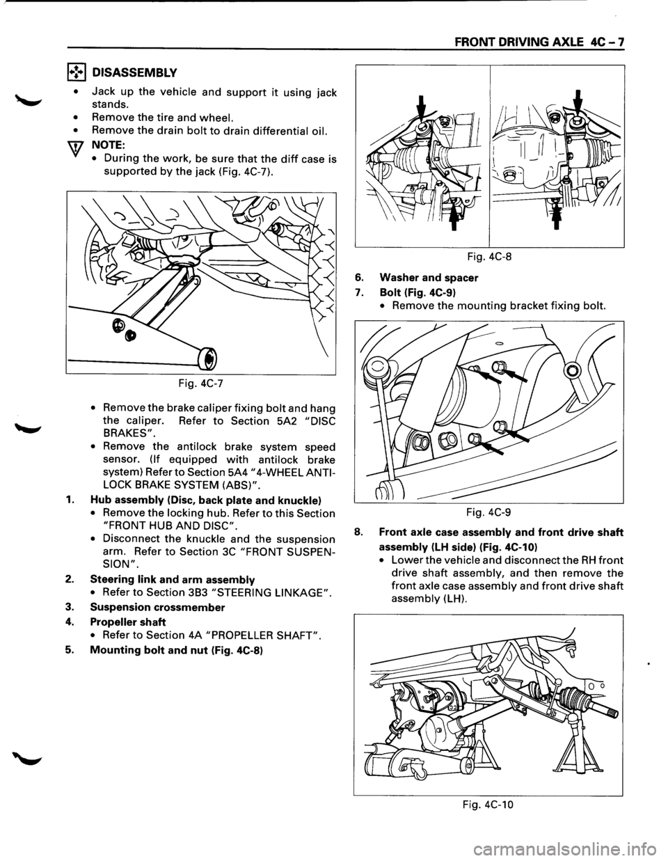
l•!•l DISASSEMBLY
•
•
•
Jack up the vehicle and support it using jack
stands.
Remove the
tire and wheel.
Remove the drain bolt to drain differential oil.
NOTE:
•
During the work, be sure that the diff case is
supported by the jack (Fig. 4C-7).
Fig.
4C-7
• Remov: the brake caliper fixing bolt and hang
the caliper. Refer to Section 5A2 "DISC
BRAKES".
•
Remove the antilock brake system speed
sensor.
(If equipped with antilock brake
system) Refer
to Section 5A4 "4-WHEEL ANTI
LOCK
BRAKE SYSTEM (ABS)".
1. Hub assembly (Disc, back plate and knuckle)
• Remove the locking hub. Refer to this Section
"FRONT HUB AND DISC".
•
Disconnect the knuckle and the suspension
arm. Refer
to Section 3C "FRONT SUSPEN
SION".
2. Steering link and arm assembly
• Refer to Section 3B3 "STEERING LINKAGE".
3. Suspension crossmember
4. Propeller shaft
• Refer to Section 4A "PROPELLER SHAFT".
5. Mounting bolt and nut (Fig. 4C-8)
FRONT DRIVING AXLE 4C-7
Fig. 4C-8
6. Washer and spacer
7. Bolt (Fig. 4C-9)
• Remove the mounting bracket fixing bolt.
Fig. 4C-9
8. Front axle case assembly and front drive shaft
assembly (LH side) (Fig. 4C-10)
• Lower the vehicle and disconnect the RH front
drive shaft assembly, and then remove the
front axle case assembly and front drive shaft
assembly (LH).
Fig. 4C-10
Page 295 of 1928
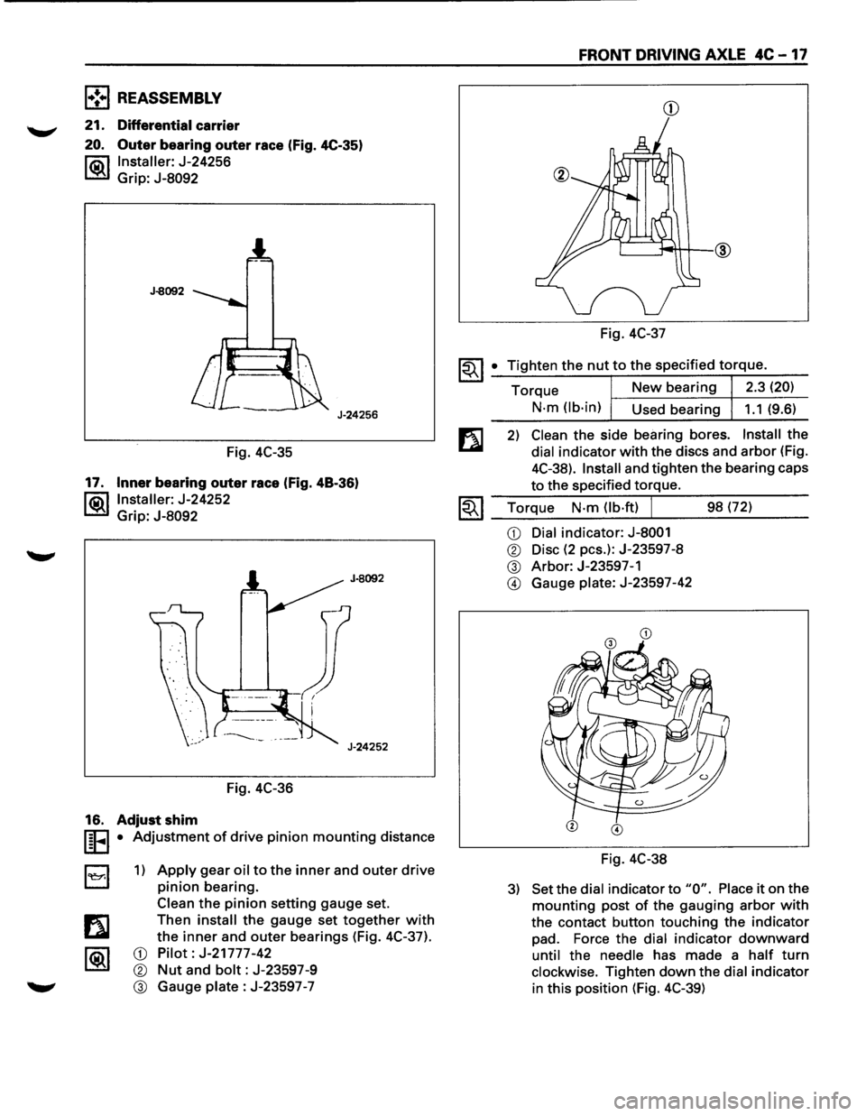
l•!•l REASSEMBLY
21. Differential carrier
20. Outer bearing outer race (Fig. 4C-35)
l"ii\1 Installer: J-24256
~ Grip: J-8092
J-8092
J-24256
Fig. 4C-35
17. Inner bearing outer race (Fig. 48-36)
l®.llnstaller: J-24252
Grip:
J-8092
Fig. 4C-36
16. Adjust shim
I§FI • Adjustment of drive pinion mounting distance
B 1) Apply gear oil to the inner and outer drive
pinion bearing.
Clean
the pinion setting gauge set.
Then
install the gauge set together with
the inner and outer bearings (Fig. 4C-37).
CD Pilot: J-21777-42
® Nut and bolt: J-23597-9
® Gauge plate : J-23597 -7
FRONT DRIVING AXLE 4C -17
CD
Fig. 4C-37
~~I _• _T:.:i:?.g.:.:h.:.:te:.:..n:...:t:.:..:h~e...:.n.:..:u:..:.t,..:.to.::......:.:th..:...e:.....:.:sp:....e:....:c_if_ie_d_t_orr-=-q-ue_. __
Torque New bearing 2.3 (20)
N-m (lb-in)
Used bearing 1.1 (9.6)
2) Clean the side bearing bores. Install the
dial indicator with the discs and arbor (Fig.
4C-38).
Install and tighten the bearing caps
to the specified torque.
1.;-. I Torque N-m (lb·ft) J 98 (72) ~ ~~--~~.---------
CD Dial indicator: J-8001
® Disc (2 pes.): J-23597-8
® Arbor: J-23597-1
@ Gauge plate: J-23597-42
Fig. 4C-38
3) Set the dial indicator to "0". Place it on the
mounting post of the gauging arbor with
the contact button touching the indicator
pad. Force the dial indicator downward
until the needle has made a half turn
clockwise. Tighten down the dial indicator
in this position (Fig. 4C-39)
Page 302 of 1928
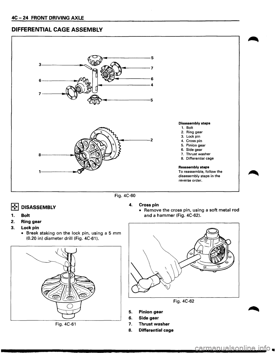
4C-24 FRONT DRIVING AXLE
DIFFERENTIAL CAGE ASSEMBLY
~~~------------6
~----------------4
Fig. 4C-60
4. Cross pin
Disassembly steps 1. Bolt 2. Ring gear
3. Lock pin 4. Cross pin 5. Pinion gear 6. Side gear 7. Thrust washer 8. Differential cage
Reassembly steps
To reassemble, follow the disassembly steps in the
reverse order.
l•!•l DISASSEMBLY
1. Bolt
• Remove the cross pin, using a soft metal rod
and a hammer (Fig. 4C-62).
2. Ring
gear
3. Lock pin
• Break staking on the lock pin, using a 5 mm
(0.20 in) diameter drill (Fig. 4C-61 ).
Fig. 4C-61
Fig. 4C-62
5. Pinion gear
6. Side gear
7. Thrust washer
8. Differential cage
•
Page 303 of 1928
![ISUZU TROOPER 1995 Manual Online (1!] INSPECTION AND REPAIR
Make necessary correction or parts replacement if
~ wear, damage, corrosion or any other abnormal
condition are found through inspection.
Check the
following part](/img/61/57183/w960_57183-302.png "ISUZU TROOPER 1995 Manual Online (1!] INSPECTION AND REPAIR
Make necessary correction or parts replacement if
~ wear, damage, corrosion or any other abnormal
condition are found through inspection.
Check the
following part")
(1!] INSPECTION AND REPAIR
Make necessary correction or parts replacement if
~ wear, damage, corrosion or any other abnormal
condition are found through inspection.
Check the
following parts.
• Ring gear, pinion gear
• Bearing
• Side gear, pinion gear, cross pin
• Differential cage, carrier
• Thrust washer
• Oil seal
Ring gear replacement
1) The ring gear should always be replaced with
the drive pinion as a set.
2) Clean the ring gear threaded holes to remove
the
locking agent.
~~~3) When installing the ring gear, apply LOCTITE
271 or equivalent to all the threaded area and
half of the unthreaded area of the bolt.
4) Discard used bolts and install new ones.
I~I __ T_o_rq~u_e __ N_·m~(l_b·_ft~l_IL_ ___ 1_0_8~(8_0_l __ __
5) Tighten the fixing bolts in a diagonal
sequence as illustrated (Fig. 4C-63).
Fig. 4C-63
H'ffil Clearance between the differential pinion and
L!l!l the cross pin measurement (Fig. 4C-64).
mm (in)
Standard Limit
0.06 -0.12 (0.002 -0.005)
0.2 (0.008)
FRONT DRIVING AXLE 4C-25
Fig. 4C-64
rfi:i1 Clearance between the side gear and the
L!l!l differential box (Fig. 4C-65)
mm (in)
Standard Limit
0.03 -0.10 (0.001 -0.004)
0.15
(0.006)
Side gear
Differential box
Fig. 4C-65
rfi:il Play in splines between the side gear and the
L!l!l axle shaft (Fig. 4C-66)
mm (in)
Standard Limit
0.08 -0.36
(0.003 -0.014) 0.5 (0.02)
Page 304 of 1928
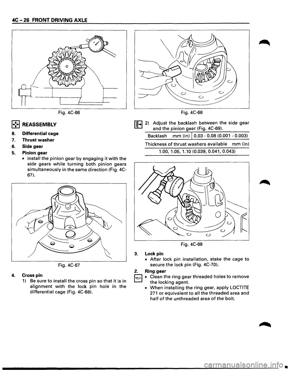
4C -26 FRONT DRIVING AXLE
l•!•l REASSEMBLY
8. Differential cage
7. Thrust washer
6. Side gear
5. Pinion gear
Fig. 4C-66
• Install the pinion gear by engaging it with the
side gears
while turning both pinion gears
simultaneously in the same direction (Fig. 4C-
67).
Fig. 4C-67
4. Cross pin
1) Be sure to install the cross pin so that it is in
alignment with the lock pin hole in the
differential cage (Fig. 4C-68). Fig.
4C-68
!EEl 2) Adjust the backlash between the side gear
and the
pinion gear (Fig. 4C-69).
Backlash
mm (in) I 0.03-0.08 (0.001 -0.003)
Thickness of thrust washers available mm (in)
1.00, 1.05, 1.10 (0.039, 0.041, 0.043)
Fig. 4C-69
3. Lock pin
• After lock pin installation, stake the cage to
secure the lock pin (Fig. 4C-70).
2. Ring gear
1~1 • Clean the ring gear threaded holes to remove
the locking agent.
• When installing the ring gear, apply LOCTITE
271 or equivalent to all the threaded area and
half of the unthreaded area of the bolt.
•
Page 306 of 1928
.
fi•28 FRONT DRIVINGk "
;: ~ ·~-¢,,
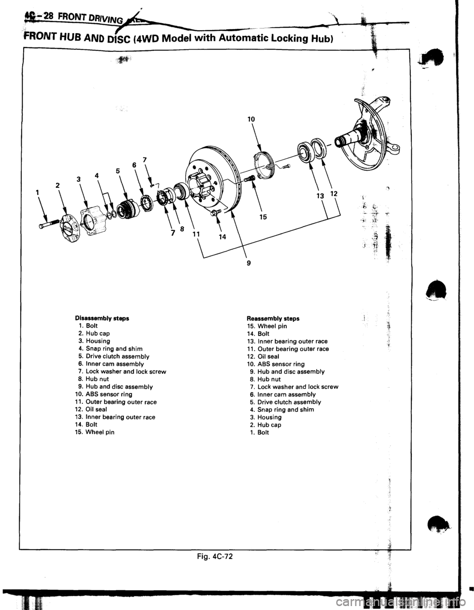
FRONT HUB AND D1SC (4WD Model with Automatic Locking Hub)
Disassembly steps 1. Bolt
2. Hub cap 3. Housing
4. Snap ring and shim
5. Drive clutch assembly 6. Inner cam assembly
7. Lock washer and lock screw 8. Hub nut
9. Hub and disc assembly 10. ABS sensor ring
11. Outer bearing outer race 12. Oil seal
13. Inner bearing outer race 14. Bolt
15. Wheel pin
Fig. 4C-72
10
9
Reassembly steps 15. Wheel pin 14. Bolt 13. Inner bearing outer race 11. Outer bearing outer race
12. Oil seal 10. ABS sensor ring 9. Hub and disc assembly 8. Hub nut 7. Lock washer and lock screw
6. Inner cam assembly 5. Drive clutch assembly 4. Snap ring and shim 3. Housing
2. Hub cap 1. Bolt
'
.f,
c. ' . .,;
)
t
~::
•
Page 307 of 1928
1•! .. 1 DISASSEMBLY
•
Shift the transfer lever to the "2H" position and
move the vehicle forward and rearward about
one meter.
• Remove the 14mm hex bolts.
• Before disassembly, jack up the front of vehicle
and
support frame with jack stands.
• Remove the disc brake caliper assembly and
hang
it on the frame with wires. Refer to Section
5A2
"DISC BRAKES".
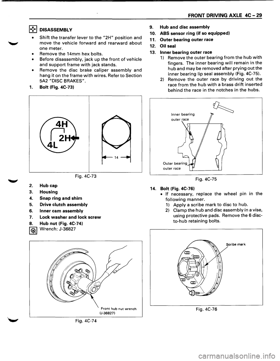
1. Bolt (Fig. 4C-73)
Fig. 4C-73
2. Hub cap
3. Housing
4. Snap ring and shim
5. Drive clutch assembly
6. Inner cam assembly
7. Lock washer and lock screw
8. Hub nut (Fig. 4C-74)
1®.1 Wrench: J-36827
Fig. 4C-74
Front hub nut wrench (J-36827)
FRONT DRIVING AXLE 4C-29
9. Hub and disc assembly
10. ABS
sensor ring (if so equipped)
11.
Outer bearing outer race
12.
Oil seal
13. Inner bearing outer race
1) Remove the outer bearing from the hub with
fingers. The inner bearing will remain in the
hub and may be removed after prying out the
inner bearing lip seal assembly (Fig. 4C-75).
2) Remove the outer race by driving out the
race from the hub with a brass drift inserted
behind
the race in the notches in the hubs.
Inner bearing
outer race
Fig. 4C-75
14.
Bolt (Fig. 4C-76)
• If necessary, replace the wheel pin in the
following manner.
1) Apply a scribe mark to disc to hub.
2) Clamp the hub and disc assembly in a vise,
using protective pads. Remove
the 6 disc
to-hub retaining bolts.
Scribe mark
Fig. 4C-76
Page 308 of 1928
4C -30 FRONT DRIVING AXLE
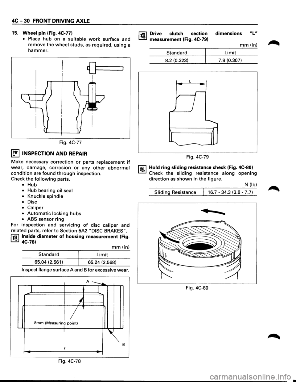
15. Wheel pin (Fig. 4C-77)
• Place
hub on a suitable work surface and
remove the
wheel studs, as required, using a
hammer.
Fig. 4C-77
I L•IINSPECTION AND REPAIR
Make necessary correction or parts replacement if
wear, damage, corrosion or any other abnormal
condition are found through inspection.
Check
the following parts.
• Hub
• Hub bearing oil seal
• Knuckle spindle
•
Disc
• Caliper
•
Automatic locking hubs
• ABS sensor ring
For inspection and servicing
of disc caliper and
related parts, refer to Section 5A2 "DISC BRAKES".
rfil Inside diameter of housing measurement (Fig.
~ 4C-78)
mm(in)
Standard Limit
65.04 (2.561)
65.24 (2.568)
Inspect flange surface A and 8 for excessive wear.
A ---....
1 I
'-/ I
i/ 8mm (Measuring point) I I
~.
e
Fig. 4C-78
rfil Drive clutch section
~ measurement (Fig. 4C-79)
Standard
8.2 (0.323)
L
Fig. 4C-79 dimensions
ulu
mm(in)
Limit
7.8
(0.307)
1@ 1 Hold ring sliding resistance check (Fig. 4C-80)
Check the sliding resistance along opening
direction as shown in the figure.
N (lb)
Sliding Resistance 16.7-34.3 (3.8-7.7)
......
Fig. 4C-80
Page 309 of 1928
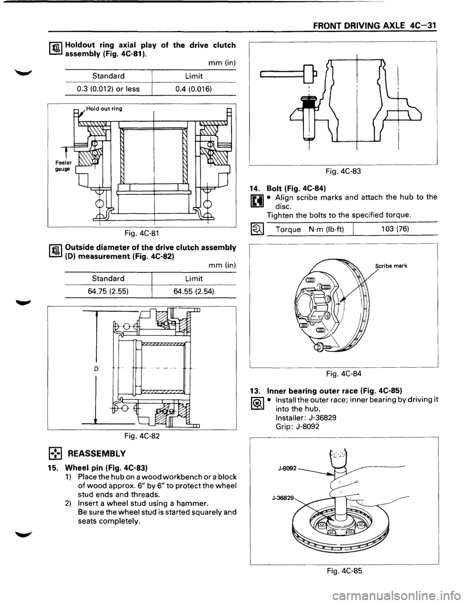
r.r.il Holdout ring axial play of the drive clutch
1..!!:.1 assembly (Fig. 4C-81 ).
mm (in)
Standard Limit
----~----------------0.3 (0.012) or less 0.4 (0.016)
Fig. 4C-81
r.r.il Outside diameter of the drive clutch assembly
1..!!:.1 (D) measurement (Fig. 4C-82)
Standard
64.75 (2.55)
Fig. 4C-82
l•! .. l REASSEMBLY
15. Wheel pin (Fig. 4C-83)
mm (in)
Limit
64.55 (2.54)
1) Place the hub on a wood workbench or a block
of wood approx. 6" by 6" to protect the wheel
stud ends and threads.
2) Insert a wheel stud using a hammer.
Be sure the wheel stud is started squarely and
seats completely.
FRONT DRIVING AXLE 4C-31
...____[)
Fig. 4C-83
14.
Bolt (Fig. 4C-84)
0 • A.lign scribe marks and attach the hub to the
1!!:!1 diSC.
Tighten the bolts to the specified torque.
~~~ Torque N·m (lb·ft) I 103 (76)
Scribe mark
Fig. 4C-84
13.
Inner bearing outer race (Fig. 4C-85)
1'?.:\1 • Install the outer race; inner bearing by driving it
l..::5::il into the hub.
Installer: J-36829
Grip:
J-8092
Fig. 4C-85