torque ISUZU TROOPER 1995 Workshop Manual
[x] Cancel search | Manufacturer: ISUZU, Model Year: 1995, Model line: TROOPER, Model: ISUZU TROOPER 1995Pages: 1928
Page 300 of 1928
4C-22 FRONT DRIVING AXLE
7. Side bearing outer race
6. Differential cage assembly
5. Bearing cap
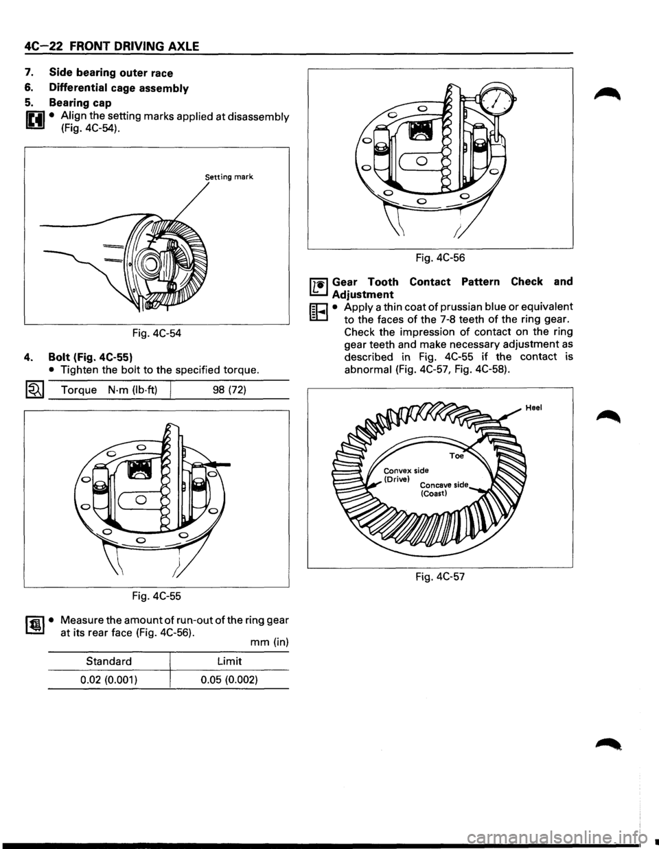
IP.il • Align the setting marks applied at disassembly
U (Fig. 4C-54).
Setting mark
Fig. 4C-54
4. Bolt (Fig. 4C-55)
• Tighten the bolt to the specified torque.
~~~ Torque N·m (lb·ft) 98 (72)
Fig. 4C-55
~·
Measure the amount of run-out of the ring gear
at its rear face (Fig. 4C-56).
mm (in)
Standard Limit
0.02
(0.001) 0.05 (0.002)
Fig. 4C-56
mil Gear Tooth Contact Pattern Check and
I.!:::..J Adjustment
r;o • Apply a thin coat of prussian blue or equivalent
ID to the faces of the 7-8 teeth of the ring gear.
Check the impression
of contact on the ring
gear teeth and make necessary adjustment
as
described in Fig. 4C-55 if the contact is
abnormal (Fig. 4C-57, Fig. 4C-58).
Fig. 4C-57
•
Page 301 of 1928
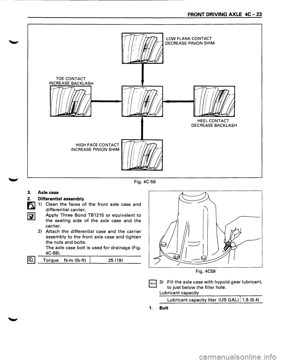
TOE CONTACT
INCREASE BACKLASH
HIGH FACE CONTACT 1
INCREASE PINION SHIM
FRONT DRIVING AXLE 4C-23
LOW FLANK CONTACT
DECREASE PINION SHIM
HEEL CONTACT
DECREASE BACKLASH
Fig. 4C-58
3. Axle case
2. Differential assembly
m 1) Clean the faces of the front axle case and
Lail differential carrier.
~~I Apply Three Bond TB1215 or equivalent to
the sealing side of the axle case and the
carrier.
2) Attach the differential case and the carrier
assembly to the front axle case and tighten
the nuts and bolts.
The axle case bolt is used for drainage (Fig.
4C-59).
~~~ Torque N-m (lb·ft) 25 (19)
Fig.
4C59
1~1 3) Fill the axle case with hypoid gear lubricant,
to just below the filler hole.
Lubricant capacity
Lubricant capacity liter (US GAL) 11.5 (0.4)
1. Bolt
Page 305 of 1928
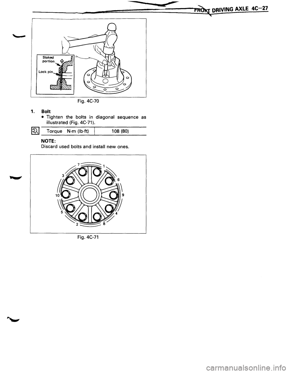
Fig. 4C-70
1. Bolt
-..... .._ .... _ _,~JII' 2
• Tighten the bolts in diagonal sequence as
illustrated (Fig. 4C-71 ).
~~~ Torque N·m (lb·ft) j 108 (80)
NOTE:
Discard used bolts and install new ones.
Fig.
4C-71
F~ DRIVING AXLE 4C 27
Page 309 of 1928
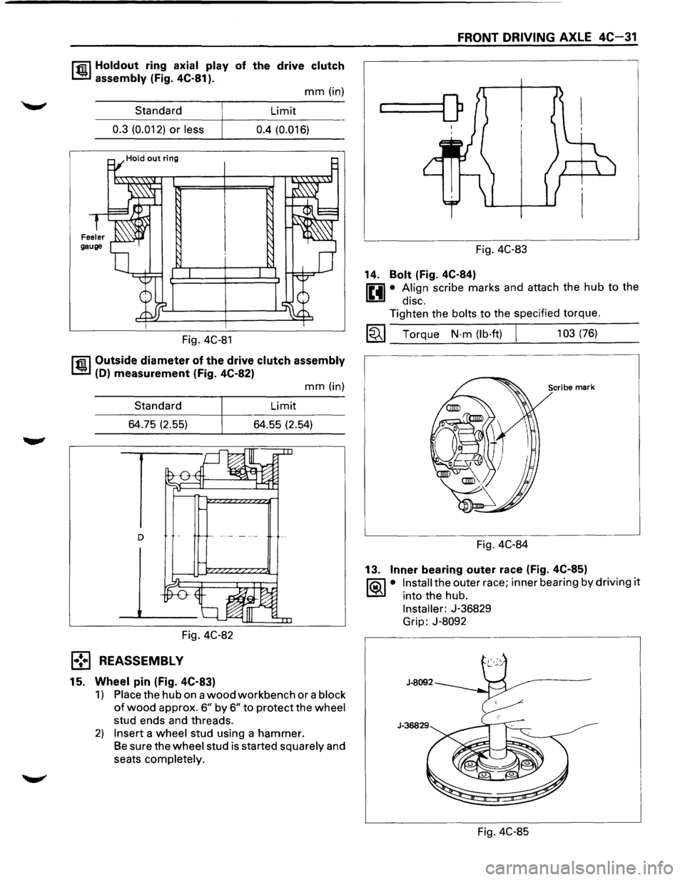
r.r.il Holdout ring axial play of the drive clutch
1..!!:.1 assembly (Fig. 4C-81 ).
mm (in)
Standard Limit
----~----------------0.3 (0.012) or less 0.4 (0.016)
Fig. 4C-81
r.r.il Outside diameter of the drive clutch assembly
1..!!:.1 (D) measurement (Fig. 4C-82)
Standard
64.75 (2.55)
Fig. 4C-82
l•! .. l REASSEMBLY
15. Wheel pin (Fig. 4C-83)
mm (in)
Limit
64.55 (2.54)
1) Place the hub on a wood workbench or a block
of wood approx. 6" by 6" to protect the wheel
stud ends and threads.
2) Insert a wheel stud using a hammer.
Be sure the wheel stud is started squarely and
seats completely.
FRONT DRIVING AXLE 4C-31
...____[)
Fig. 4C-83
14.
Bolt (Fig. 4C-84)
0 • A.lign scribe marks and attach the hub to the
1!!:!1 diSC.
Tighten the bolts to the specified torque.
~~~ Torque N·m (lb·ft) I 103 (76)
Scribe mark
Fig. 4C-84
13.
Inner bearing outer race (Fig. 4C-85)
1'?.:\1 • Install the outer race; inner bearing by driving it
l..::5::il into the hub.
Installer: J-36829
Grip:
J-8092
Fig. 4C-85
Page 310 of 1928
4C-32 FRONT DRIVING AXLE
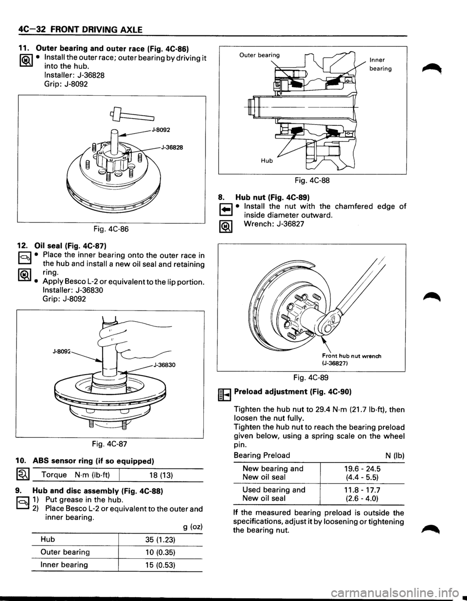
11. Outer bearing and outer race (Fig. 4C-86)
li5\l • Install the outer race; outer bearing by driving it
L::!iil into the hub.
Installer: J-36828
Grip: J-8092
Fig. 4C-86
12. Oil seal (Fig. 4C-87)
r::::l • Place the inner bearing onto the outer race in
D the hub and install a new oil seal and retaining
~. ring.
Apply Besco L-2 or equivalent to the lip portion.
Installer: J-36830
Grip: J-8092
Fig. 4C-87
10. ABS sensor ring (if so equipped)
~~~ Torque N·m (lb·ft) [ 18 (13)
9. Hub and disc assembly (Fig. 4C-88)
r::::l 1) Put grease in the hub.
D 2) Place Besco L-2 or equivalent to the outer and
inner bearing.
g (oz)
Hub 35 (1.23)
Outer bearing 10 (0.35)
Inner bearing 15 (0.53)
Outer bearing Inner
bearing
Fig. 4C-88
8. Hub nut (Fig. 4C-89)
r=1 • Install the nut with the chamfered edge of
~ inside diameter outward.
1®..1 Wrench: J-36827
Front hub nut wrench (J-36827)
Fig. 4C-89
IEEI Preload adjustment (Fig. 4C-90)
Tighten the hub nut to 29.4 N·m (21.7 lb·ft), then
loosen the
nut fully.
Tighten the hub nut to reach the bearing preload
given below, using a spring scale on the wheel
pin.
Bearing
Preload
New bearing and
New oil seal
Used bearing and
New
oil seal
19.6-24.5
(4.4-5.5)
11.8-17.7
(2.6-4.0)
N (lb)
If the measured bearing preload is outside the
specifications, adjust
it by loosening or tightening
the bearing nut.
•
Page 314 of 1928
4C-36 FRONT DRIVING AXLE
Fig. 4C-103
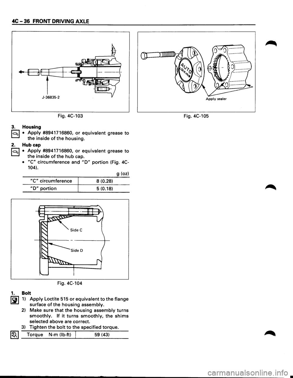
3. Housing
l<:::~t>l • Apply #8941716860, or equivalent grease to
the inside of the housing.
2. Hub cap
l<:::~t>l • Apply #8941716860, or equivalent grease to
the inside of the hub cap.
• "C" circumference and "D" portion (Fig. 4C-
104).
g (oz)
"C" circumference
8 (0.28)
"D" portion 5 (0.18)
Fig. 4C-104
1. Bolt
l!i!l 1) Apply Loctite 515 or equivalent to the flange
surface of the housing assembly.
2) Make sure that the housing assembly turns
smoothly. If it turns smoothly, the shims
selected above are correct.
3) Tighten the bolt to the specified torque.
~~~ Torque N·m (lb.ft) J 59 (43)
Apply sealer
Fig. 4C-105
Page 316 of 1928
4C-38 FRONT DRIVING AXLE
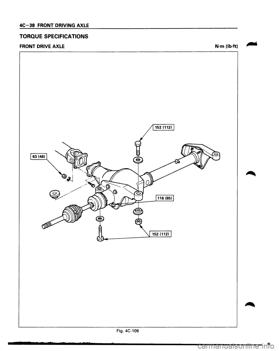
TORQUE SPECIFICATIONS
FRONT DRIVE AXLE
Fig. 4C-106
N·m (lb·ft)
•
Page 321 of 1928
HYDRAULIC BRAKES SA-1
BRAKES
w CAUTION:
• All
brake attaching fasteners are an important attaching part in that they could affect performance of vital
parts and systems, and/or could result in major repair expense. They must be replaced with one of the same
part
number or with an equivalent part if replacement becomes necessary. Do not use replacement parts of
lesser quality or substitute design. Torque values must be used as specified during reassembly to assure
proper retention
of these parts.
CONTENTS
Hydraulic Brakes . . . . . . . . . . . . . . . . . . . . . . . . . . . . . . . . . . . . . . . . . . . . . . . . . . . . . . . . . . . . . . Section SA
Brake Booster System ........................................................ Section 5A1
Disc Brakes . . . . . . . . . . . . . . . . . . . . . . . . . . . . . . . . . . . . . . . . . . . . . . . . . . . . . . . . . . . . . . . . . . Section 5A2
Rear
Wheel Antilock Brake System (RWAL) .................................... Section 5A3
4-Wheel Antilock Brake System (ABS) ......................................... Section 5A4
Parking Brakes . . . . . . . . . . . . . . . . . . . . . . . . . . . . . . . . . . . . . . . . . . . . . . . . . . . . . . . . . . . . . . . .
Section 5C
SECTION 5A
HYDRAULIC BRAKES
CONTENTS
Brake System Diagnosis ................ SA-2
Road
Testing the Brakes . . . . . . . . . . . . . . SA-2
Brake
Fluid Leaks . . . . . . . . . . . . . . . . . . . . SA-2
Warning Light Operation . . . . . . . . . . . . . SA-2
Antilock Brake System (RWAL or ABS) . SA- 2
Diagnosis of Brake System . . . . . . . . . . . . . . SA-3
On-Vehicle Service .................... SA- S
Filling Master Cylinder Reservoir . . . . . . . SA-S
Deterioration of Brake Fluid . . . . . . . . . . . SA-S
Leakage
of Brake Fluid . . . . . . . . . . . . . . . SA-S
Bleeding Brake Hydraulic System . . . . . . SA-S
Flushing Brake Hydraulic System . . . . . . SA-6
Brake Pipes
and Hoses . . . . . . . . . . . . . . . SA-6
Brake Hose
Inspection . . . . . . . . . . . . . . . SA-6
Brake Hose
Replacement . . . . . . . . . . . . . SA-7
Brake Pipe
Replacement . . . . . . . . . . . . . . SA-8
Combination Valve/P & B Valve . . . . . . . SA-9
Valve Replacement . . . . . . . . . . . . . . . . . . SA-1 0
Inspection of Brake Pad Lining . . . . . . . . SA-11
Inspection of Brake Rotors . . . . . . . . . . . . SA-11
Brake Pedal Assembly .................. SA-13 •
Checking Pedal Height ................ SA-13
Checking Pedal Travel ................ SA-13
Brake
Pedal Replacement ............. SA-14
Stoplight Switch Replacement ......... SA-1S
Master Cylinder Assembly ............... SA-16
General Description .................. SA-16
On-Vehicle Service ................... SA-17
Unit Repair .......................... SA-19
Main Data and Specifications ............ SA-21
General Specifications ................ SA-21
Torque Specifications ................ SA-21
Special Tools .......................... SA-22
Page 327 of 1928
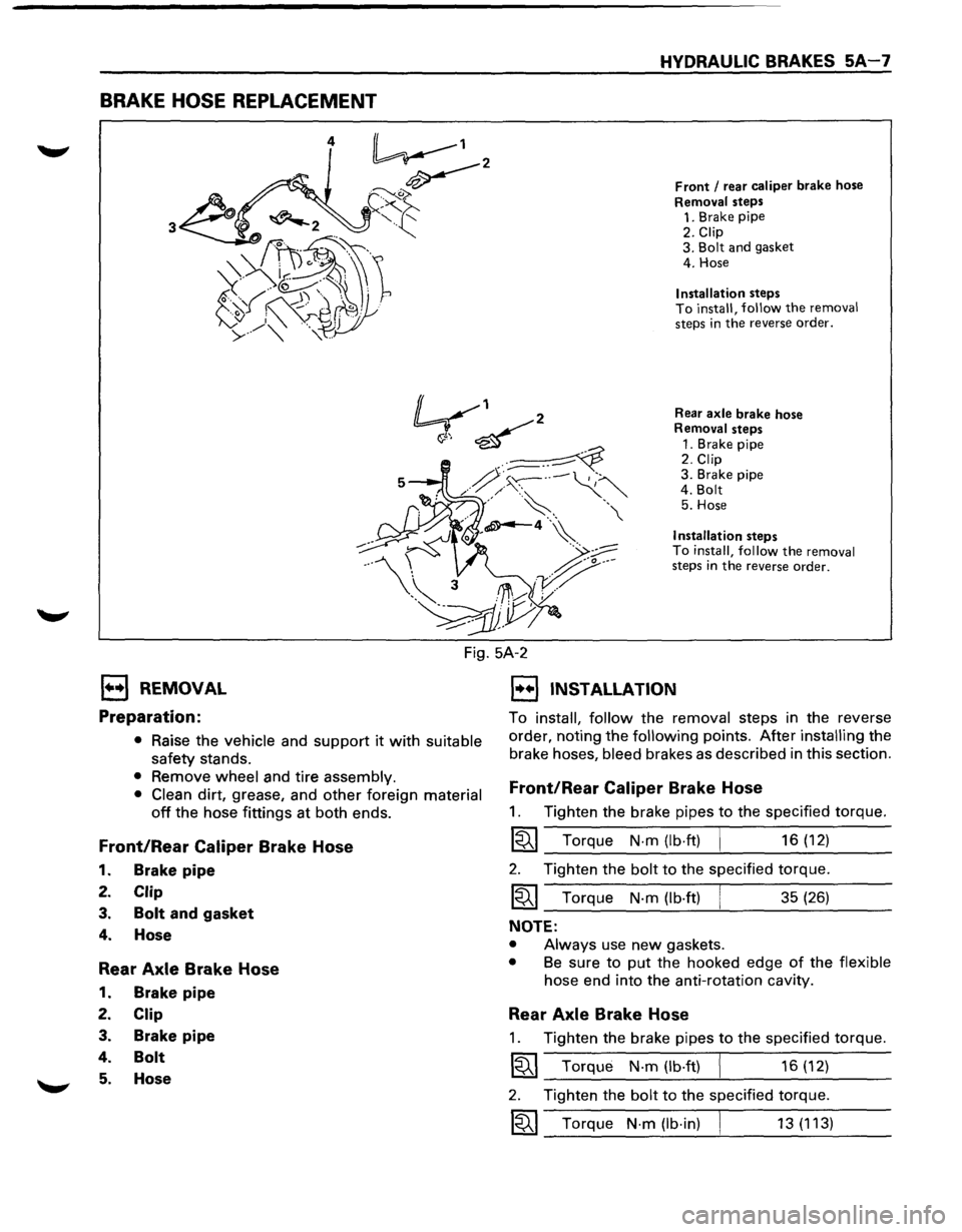
BRAKE HOSE REPLACEMENT
HYDRAULIC BRAKES 5A-7
Front I rear caliper brake hose
Removal steps 1. Brake pipe
2. Clip 3. Bolt and gasket
4. Hose
Installation steps To install, follow the removal steps in the reverse order.
Rear axle brake hose Removal steps
1. Brake pipe
2. Clip 3. Brake pipe
4. Bolt
5. Hose
Installation steps To install, follow the removal steps in the reverse order.
Fig. 5A-2
l••l REMOVAL
Preparation:
• Raise the vehicle and support it with suitable
safety stands.
• Remove wheel and tire assembly.
• Clean dirt, grease, and other foreign material
off the hose fittings at both ends.
Front/Rear Caliper Brake Hose
1. Brake pipe
2. Clip
3. Bolt and gasket
4. Hose
Rear Axle Brake Hose
1. Brake pipe
2. Clip
3. Brake pipe
4. Bolt
5. Hose
1••1 INSTALLATION
To install, follow the removal steps in the reverse
order, noting the following points. After installing the
brake
hoses, bleed brakes as described in this section.
Front/Rear Caliper Brake Hose
1. Tighten the brake pipes to the specified torque.
1«1 Torque N-m (lb·ft) 16 (12)
2. Tighten the bolt to the specified torque.
1«1 Torque N-m (lb-ft) 35 (26)
NOTE:
• Always use new gaskets.
• Be sure to put the hooked edge of the flexible
hose end into the anti-rotation cavity.
Rear Axle Brake Hose
1. Tighten the brake pipes to the specified torque.
1«1 Torque N-m (lb-ft) 16 (12)
2. Tighten the bolt to the specified torque.
1«1 Torque N·m (lb·in) 13 (113)
Page 328 of 1928
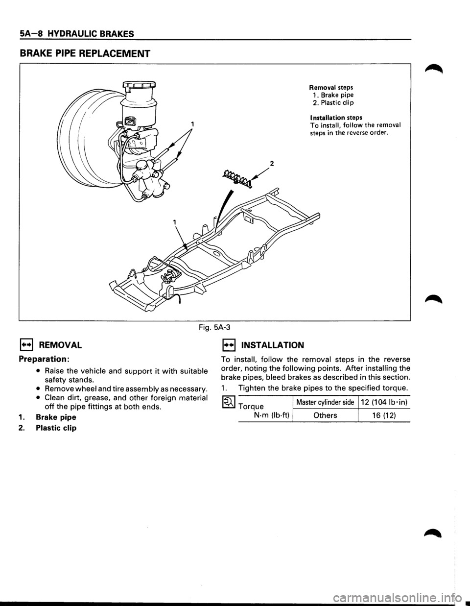
SA-8 HYDRAULIC BRAKES
BRAKE PIPE REPLACEMENT
Removal steps
1. Brake pipe
2. Plastic
clip
I nstallation
steps
To install, follow the removal steps in the reverse order.
Fig. 5A-3
1••1 REMOVAL
Preparation:
• Raise the vehicle and support it with suitable
safety stands.
• Remove wheel and tire assembly as necessary.
• Clean dirt, grease, and other foreign material
off the pipe fittings at both ends.
1. Brake pipe
2. Plastic clip
1••1 INSTALLATION
To install, follow the removal steps in the reverse
order, noting the
following points. After installing the
brake pipes,
bleed brakes as described in this section.
1. Tighten the brake pipes to the specified torque.
~~~ Master cylinder side 12 (104 lb·in) Torque
N·m(lb·ft) Others 16(12)