torque ISUZU TROOPER 1995 Workshop Manual
[x] Cancel search | Manufacturer: ISUZU, Model Year: 1995, Model line: TROOPER, Model: ISUZU TROOPER 1995Pages: 1928
Page 494 of 1928
5C-4 PARKING BRAKES
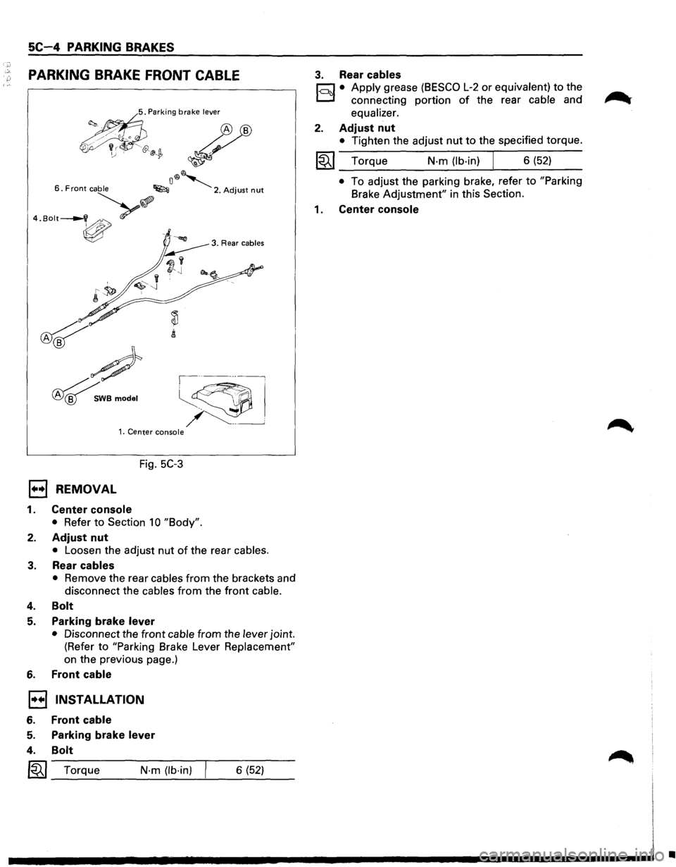
PARKING BRAKE FRONT CABLE
<.~ '"''"' brnke '""" ~
~~~ ~ ~
o®~ 6. Front cable ~ 2. Adjust nut
··"""-v>.?
~
~
#
~WBmodel
,----~
~~
~ ~--___j 1. Center console
Fig. 5C-3
1••1 REMOVAL
1. Center console
• Refer to Section 10 "Body".
2. Adjust nut
• Loosen the adjust nut of the rear cables.
3. Rear cables
• Remove the rear cables from the brackets and
disconnect the cables
from the front cable.
4. Bolt
5. Parking brake lever
• Disconnect the front cable from the lever joint.
(Refer to
"Parking Brake Lever Replacement"
on the previous page.)
6. Front cable
1•+1 INSTALLATION
6. Front cable
5.
4.
Parking brake lever
Bolt
I~I_T_o_rq_u_e ___ N_·_m_(lb_·_in_) --'---6_(_5_2) __
3. Rear cables
r;:::;:] • Apply grease (BESCO L-2 or equivalent) to the
D connecting portion of the rear cable and
equalizer.
2. Adjust nut
• Tighten the adjust nut to the specified torque.
~~~ Torque N-m (lb-in) J 6 (52)
• To adjust the parking brake, refer to "Parking
Brake
Adjustment" in this Section.
1 . Center console
•
Page 496 of 1928
5C-6 PARKING BRAKES
1••1 INSTALLATION
15. Rear cable
hl • Apply grease (BESCO L-2 or equivalent) to the
D connecting portion of the rear cable and
equalizer.
14. Equalizer
13. Back plate
12. Adjust nut
• Tighten the adjust nut to the specified torque.
1~1 Torque N-m (lb-in) I 6 (52)
• To adjust the parking brake, refer to "Parking
Brake Adjustment" in this Section.
11,10, 9. Clip
~~~ Torque N·m (lb·in) I 6 (52)
8. Cable fixing bolt
• Tighten the cable fixing bolt to the specified
torque.
~~~ Torque N·m (lb·in) 6 (52)
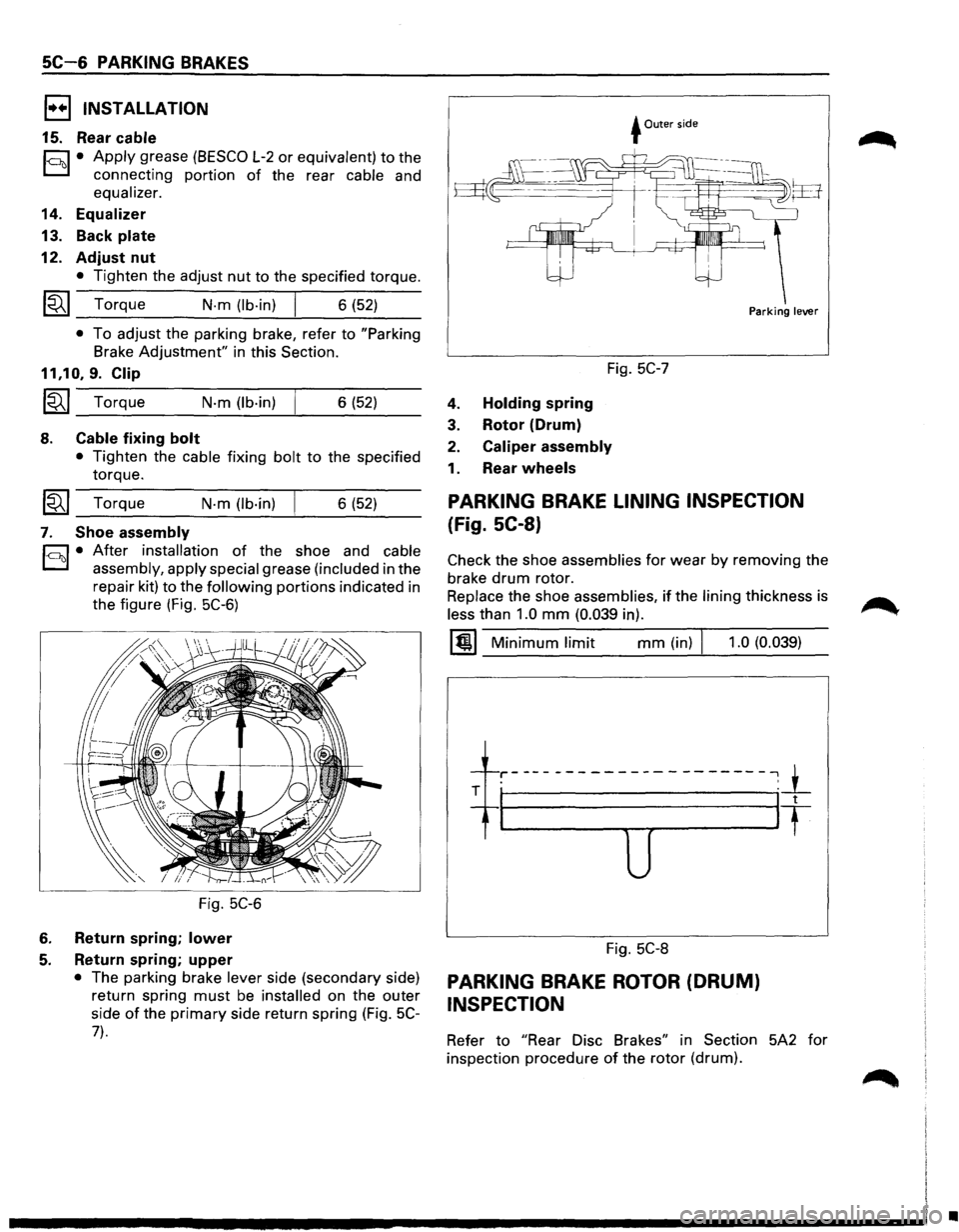
7. Shoe assembly
h1 • After installation of the shoe and cable
D assembly, apply special grease (included in the
repair kit)
to the following portions indicated in
the figure (Fig.
5C-6)
Fig. 5C-6
6. Return spring; lower
5. Return spring; upper
• The parking brake lever side (secondary side)
return spring
must be installed on the outer
side
of the primary side return spring (Fig. 5C-
7).
+Outer side
Fig. 5C-7
4. Holding spring
3. Rotor (Drum)
2. Caliper assembly
1. Rear wheels
Parking lever
PARKING BRAKE LINING INSPECTION
(Fig. SC-8)
Check the shoe assemblies for wear by removing the
brake
drum rotor.
Replace the shoe assemblies, if the lining thickness is
less than 1.0 mm (0.039 in).
1@1 Minimum limit mm (in) J 1.0 (0.039)
-1---r-----------------------,_1_ . '
T I It
u
Fig. 5C-8
PARKING BRAKE ROTOR (DRUM)
INSPECTION
Refer to "Rear Disc Brakes" in Section 5A2 for
inspection procedure
of the rotor (drum).
•
Page 497 of 1928
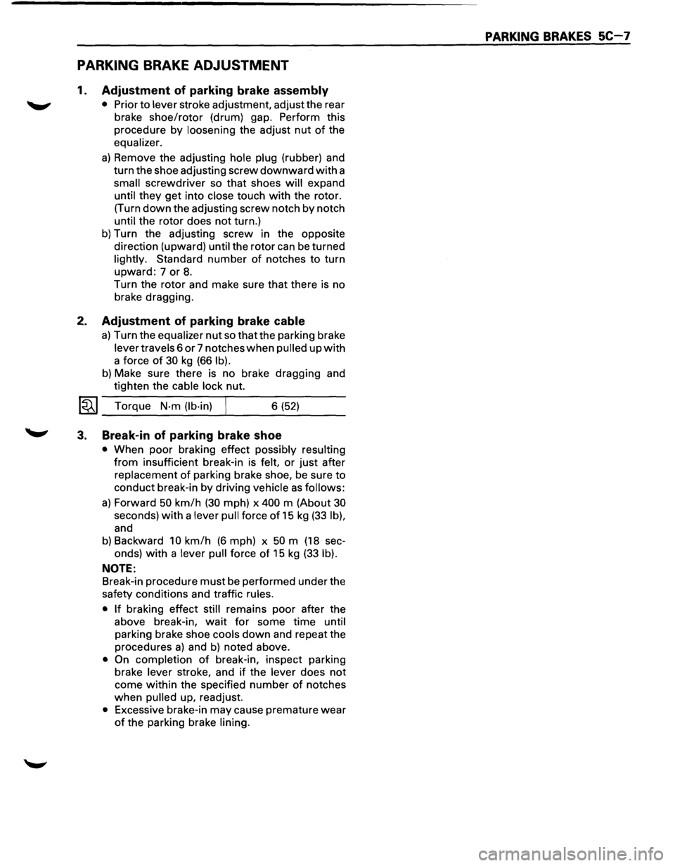
PARKING BRAKE ADJUSTMENT
1. Adjustment of parking brake assembly
• Prior to lever stroke adjustment, adjust the rear
brake
shoe/rotor (drum) gap. Perform this
procedure
by loosening the adjust nut of the
equalizer.
a) Remove the adjusting hole plug (rubber) and
turn the shoe adjusting screw
downward with a
small screwdriver so that shoes will expand
until
they get into close touch with the rotor.
(Turn
down the adjusting screw notch by notch
until the rotor does not turn.)
b) Turn the adjusting screw in the opposite
direction (upward) until the rotor can
be turned
lightly. Standard
number of notches to turn
upward: 7 or 8.
Turn the rotor and make sure that there is no
brake dragging.
2. Adjustment of parking brake cable
a) Turn the equalizer nut so that the parking brake
lever travels 6
or 7 notches when pulled up with
a force of 30 kg (66 lb).
b) Make sure there is no brake dragging and
tighten the cable lock nut.
l~l Torque N·m (lb·in) 6 (52)
3. Break-in of parking brake shoe
• When poor braking effect possibly resulting
from insufficient break-in is felt, or just after
replacement
of parking brake shoe, be sure to
conduct break-in by driving vehicle as follows:
a) Forward 50 km/h (30 mph) x 400 m (About 30
seconds) with a lever pull force of 15 kg (33 lb),
and
b) Backward 10 km/h (6 mph) x 50 m (18 sec-
onds)
with a lever pull force of 15 kg (33 lb).
NOTE:
Break-in procedure must be performed under the
safety conditions and traffic rules.
• If braking effect still remains poor after the
above break-in,
wait for some time until
parking brake shoe cools
down and repeat the
procedures
a) and b) noted above.
• On completion of break-in, inspect parking
brake lever stroke, and
if the lever does not
come within the specified number of notches
when pulled up, readjust.
• Excessive brake-in may cause premature wear
of the parking brake lining.
PARKING BRAKES SC-7
Page 498 of 1928
SC-8 PARKING BRAKES
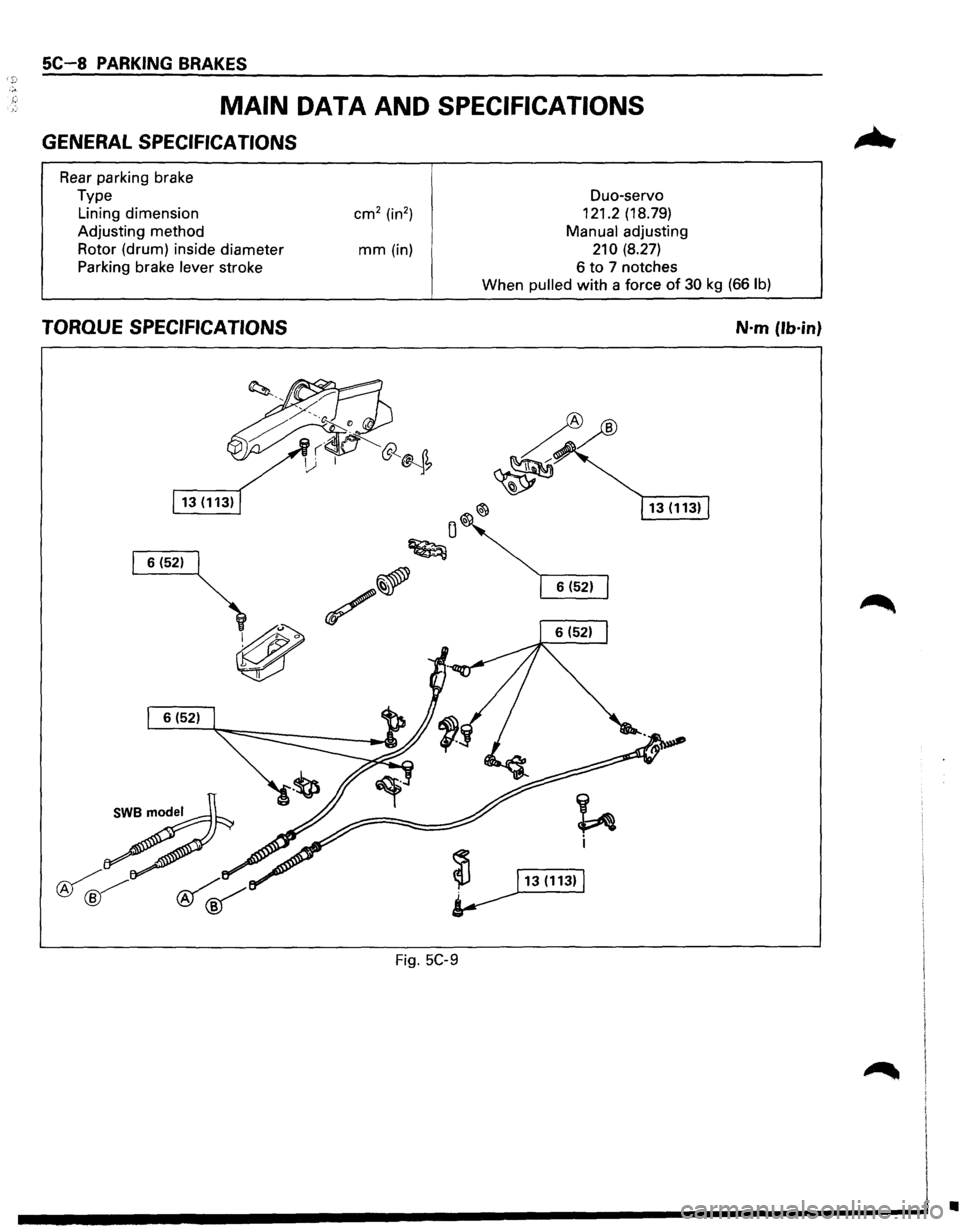
MAIN DATA AND SPECIFICATIONS
GENERAL SPECIFICATIONS
Rear parking brake
Type Lining dimension
Adjusting method
Rotor (drum) inside diameter
Parking brake
lever stroke
mm (in) Duo-servo
121.2
(18.79)
Manual adjusting
210 (8.27)
6 to 7 notches
When pulled
with a force of 30 kg (66 lb)
TORQUE SPECIFICATIONS N·m (lb·in}
Fig. 5C-9
•
Page 502 of 1928
6-4 ENGINE DIAGNOSIS
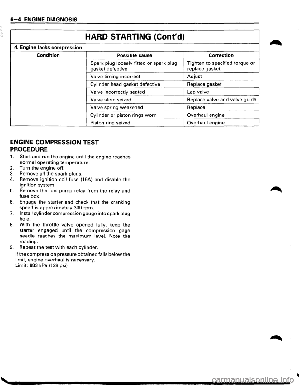
HARD STARTING (Cont'd)
4. Engine lacks compression
Condition Possible cause
Spark plug loosely fitted or spark plug
gasket defective
Valve timing incorrect
Cylinder head gasket defective
Valve incorrectly seated
Valve stem seized
Valve spring weakened
Cylinder or piston rings worn
Piston ring seized
ENGINE COMPRESSION TEST
PROCEDURE
1. Start and run the engine until the engine reaches
normal operating temperature.
2. Turn the engine off.
3. Remove all the spark plugs.
4. Remove ignition coil fuse (15A) and disable the
ignition system.
5. Remove the fuel pump relay from the relay and
fuse box.
6. Engage the starter and check that the cranking
speed is approximately
300 rpm.
7. Install cylinder compression gauge into spark plug
hole.
8. With the throttle valve opened fully, keep the
starter engaged
until the compression gage
needle reaches the
maximum level. Note the
reading.
9. Repeat the test with each cylinder.
If
the compression pressure obtained falls below the
limit, engine overhaul is necessary.
Limit; 883
kPa (128 psi) Correction
Tighten
to specified torque or
replace gasket
Adjust
Replace gasket
Lap
valve
Replace valve
and valve guide
Replace
Overhaul engine
Overhaul engine.
Page 518 of 1928
6A-2 GENERAL ENGINE MECHANICAL
NOTE:
•
During disassembly, be sure that the valve train
components are kept
together and identified so
that they can be re-installed in their original
locations.
• Before removing the cylinder head from the
engine and before disassembling the valve
mechanism, perform a compression test and note
the results.
1•! .. 1 DISASSEMBLY
(SOHC)
1. Camshaft timing pulley
2. Front plate
3. Camshaft bracket fixing bolts
4. Camshaft, oil seal and camshaft end plug
• Remove them with camshaft bracket.
5. Rockershaft assembly (Exhaust side)
6. Rockershaft assembly (Intake side)
7. Spark plug
\fl CAUTION:
VI • Do not remove the spark plugs when the head
and plugs are hot.
• Clean dirt and debris from spark plug recess
areas.
(DOHC)
1. Camshaft timing pulley
2. Front plate
3. Camshaft bracket fixing bolts
4. Chain tensioner fixing bolts
5. Camshaft, oil seal and camshaft end plug
• Remove them with chain and chain tensioner
6. Swing arm.
7. Hydraulic lash adjusters (HLA)
NOTE:
Immerse HLA in engine oil, taking care nottoturn it
upside down or sideways in order to prevent any
air
from entering into HLA.
8. Spark plug
\flCAUTION:
VI • Do not remove the spark plugs when the head
and plugs are hot.
• Clean dirt and debris from spark plug recess
areas.
f}l CLEAN
• Cylinder head
Carefully remove
all varnish, soot and carbon
to the bare metal. Do not use a motorized wire
brush on any gasket sealing surface.
IL'~'IINSPECTION AND REPAIR
• Cylinder head gasket and mating surfaces for
leaks, corrosion and blow-by. If the gasket has
failed, determine the cause. Insufficient
torque on head bolts
Improper installation
Loose
or warped cylinder head
Missing
dowel pins
- Warped case surface
1. Cylinder head bolts for damaged threads or
stretching and damaged heads caused by
improper use of tools.
\fl CAUTION:
VI Replace used cylinder head bolts.
2. Cylinder head for cracks, especially between valve
seats and in the exhaust ports.
3. Cylinder head deck for corrosion, sand particles in
head and porosity.
\fl CAUTION:
VI Do not attemptto weld the cylinder head. Replace
it.
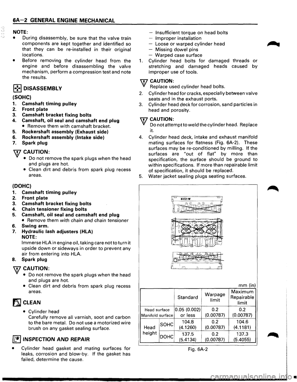
4. Cylinder head deck, intake and exhaust manifold
mating surfaces for flatness (Fig. 6A-2). These
surfaces
may be re-conditioned by milling. If the
surfaces are
"out of flat" by more than
specification, the surface should be ground
to
within specifications. If more than repairable limit
of specification, it should be replaced.
5. Water jacket sealing plugs seating surfaces.
IIVD1-w 8~
~ I 0 I ' 0 0 I 0
mm (in)
Warpage
Maximum
Standard Repairable limit limit
Head surface 0.05 (0.002) 0.2
0.2
Manifold surface or less (0.00787) (0.00787)
SOHC 104.8 0.2
104.6
Head (4.1260) (0.00787) (4.1181)
height
DOHC 137.5 0.2 137.3
(5.4134)
(0.00787) (5.4055)
Fig. 6A-2
•
Page 519 of 1928
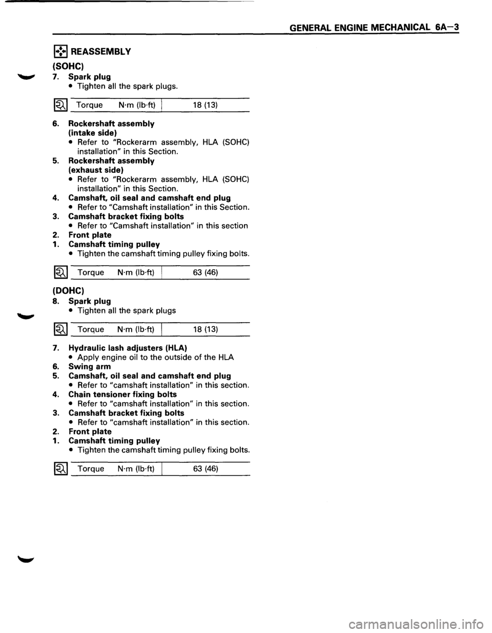
1•!.,1 REASSEMBL V
{SOHC)
~ 7. Spark plug
• Tighten all the spark plugs.
1~1 Torque N·m (lb·ft)
6. Rockershaft assembly
(intake side)
18 (13)
• Refer to "Rockerarm assembly, HLA (SOHC)
installation" in this Section.
5. Rockershaft assembly
(exhaust side)
• Refer to "Rockerarm assembly, HLA (SOHC)
installation" in this Section.
4. Camshaft, oil seal and camshaft end plug
• Refer to "Camshaft installation" in this Section.
3.
Camshaft bracket fixing bolts
• Refer to "Camshaft installation" in this section
2. Front plate
1. Camshaft timing pulley
• Tighten the camshaft timing pulley fixing bolts.
~~~ Torque N·m (lb·ft) 63 (46)
(DOHC)
8. Spark plug
• Tighten all the spark plugs
~~~ Torque N·m (lb·ft) I 18 (13)
7. Hydraulic lash adjusters (HLA)
• Apply engine oil to the outside of the HLA
6. Swing arm
5. Camshaft, oil seal and camshaft end plug
• Refer to "camshaft installation" in this section.
4. Chain tensioner fixing bolts
• Refer to "camshaft installation" in this section.
3. Camshaft bracket fixing bolts
• Refer to "camshaft installation" in this section.
2. Front plate
1. Camshaft timing pulley
• Tighten the camshaft timing pulley fixing bolts.
1~1 Torque N·m (lb·ft) 63 (46)
GENERAL ENGINE MECHANICAL 6A-3
Page 528 of 1928
6A-12 GENERAL ENGINE MECHANICAL
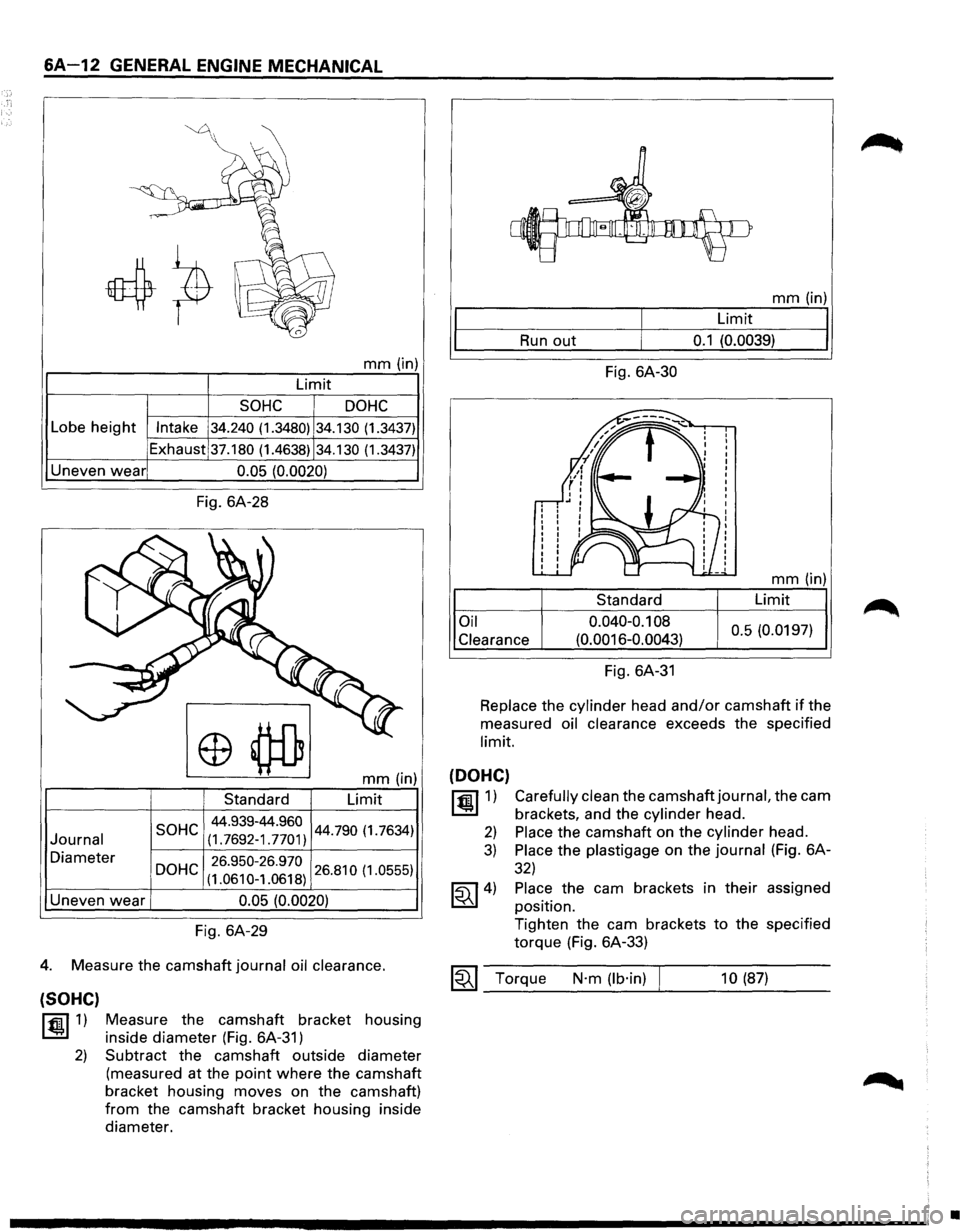
mm (in)
Limit
SOHC DOHC
Lobe height Intake 34.240 (1.3480) 34.130 (1.3437)
Exhaust 37.180 (1.4638) 34.130 (1.3437)
Uneven wear 0.05 (0.0020)
Journal
Diameter
Uneven
wear
Fig. 6A-28
mm (in)
Standard Limit
44.939-44.960 SOHC (1.
7692 _
1 _7701) 44.790 (1.7634)
26.950-26.970 DOHC (1 _
0610 _
1 _
0618 )
26.810 (1.0555)
0.05 (0.0020)
Fig. 6A-29
4. Measure the camshaft journal oil clearance.
(SOHC)
~1) Measure the camshaft bracket housing
inside diameter (Fig. 6A-31)
2) Subtract the camshaft outside diameter
(measured at the
point where the camshaft
bracket housing moves on the camshaft)
from the camshaft bracket housing inside
diameter.
mm (in)
Limit
Run out 0.1 (0.0039)
Fig. 6A-30
mm (in)
Limit
Oil
Clearance
0.040-0.1 08
(0.0016-0.0043) 0.5
(0.0197)
Fig. 6A-31
Replace the cylinder head
and/or camshaft if the
measured oil clearance exceeds the specified
limit.
(DOHC)
~1) Carefully clean the camshaft journal, the cam
brackets, and the
cylinder head.
2) Place the camshaft on the cylinder head.
3) Place the plastigage on the journal (Fig. 6A-
32)
~4) Place the cam brackets in their assigned
position.
Tighten the cam brackets
to the specified
torque (Fig. 6A-33)
~~~ Torque N·m (lb·in) 10 (87)
•
Page 529 of 1928
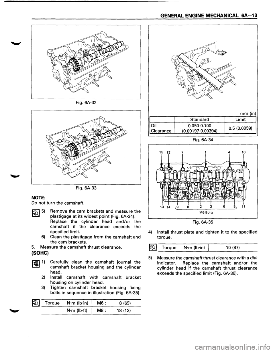
Fig. 6A-32
Fig. 6A-33
NOTE:
Do not turn the camshaft.
~~~5) Remove the cam brackets and measure the
plastigage at its widest point (Fig. 6A-34).
Replace the cylinder head and/or the
camshaft
if the clearance exceeds the
specified
limit.
6) Clean the plastigage from the camshaft and
the cam brackets.
5. Measure the camshaft thrust clearance.
(SOHC)
~1) Carefully clean the camshaft journal the
camshaft bracket housing and the
cylinder
head.
2) Install camshaft with camshaft bracket
housing on
cylinder head.
3) Tighten camshaft bracket housing fixing
bolts in sequence in illustration (Fig. 6A-35).
~~~ Torque N·m (lb·in)
N·m (lb·ft) M6:
M8:
8 (69)
18 (13)
GENERAL ENGINE MECHANICAL 6A-13
Oil
Clearance
15 12
Standard
0.050-0.100
(0.00197-0.00394)
Fig. 6A-34
7
mm (in)
Limit
0.5 (0.0059)
4 10
13 14 \-.:._9 __ 8 ___ 2 ---~_=.3 _ ___:6::__--=.5 1 11
M6 Bolts
Fig. 6A-35
4) Install thrust plate and tighten it to the specified
torque.
1~1 Torque N·m (lb·in) I 10 (87)
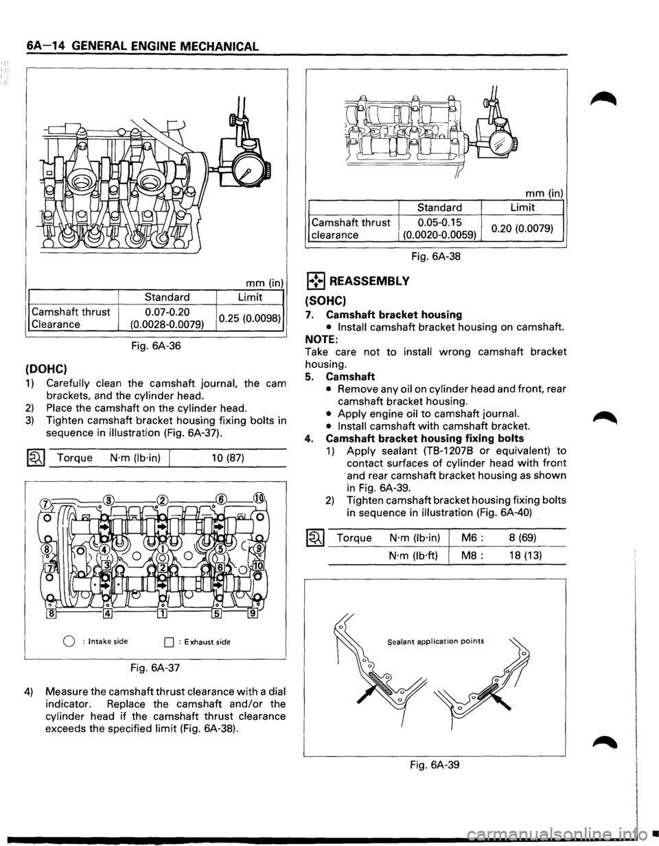
5) Measure the camshaft thrust clearance with a dial
indicator. Replace the camshaft and/or the
cylinder head if the camshaft thrust clearance
exceeds the specified limit (Fig. 6A-36).
Page 530 of 1928
6A-14 GENERAL ENGINE MECHANICAL
Camshaft thrust
Clearance
(DOHC}
Standard
0.07-0.20
(0.0028-0.0079)
Fig. 6A-36
mm (in)
Limit
0.25 (0.0098)
1) Carefully clean the camshaft journal, the cam
brackets, and the
cylinder head.
2) Place the camshaft on the cylinder head.
3) Tighten camshaft bracket housing fixing bolts in
sequence in
illustration (Fig. 6A-37).
~~~ Torque N·m (lb·in) 10 (87)
Q : Intake side O : Exhaust side
Fig. 6A-37
4) Measure the camshaft thrust clearance with a dial
indicator. Replace the camshaft and/or the
cylinder head if the camshaft thrust clearance
exceeds the specified limit (Fig. 6A-38).
mm (in)
Standard Limit
Camshaft thrust 0.05-0.15 0.20 (0.0079)
clearance (0.0020-0.0059)
l•!•l REASSEMBLY
(SOHC}
Fig. 6A-38
7. Camshaft bracket housing
• Install camshaft bracket housing on camshaft.
NOTE:
Take care not to install wrong camshaft bracket
housing.
5. Camshaft
• Remove any oil on cylinder head and front, rear
camshaft bracket housing.
• Apply engine oil to camshaft journal.
• Install
camshaft with camshaft bracket.
4. Camshaft bracket housing fixing bolts
1) Apply sealant (TB-12078 or equivalent) to
contact surfaces
of cylinder head with front
and rear camshaft bracket housing as shown
in Fig. 6A-39.
2) Tighten camshaft bracket housing fixing bolts
in sequence in illustration (Fig. 6A-40)
~~~ Torque N·m (lb·in)
N·m (lb·ft) M6:
M8:
Sealant application points
Fig. 6A-39 8
(69)
18 (13)
•