torque ISUZU TROOPER 1995 Manual Online
[x] Cancel search | Manufacturer: ISUZU, Model Year: 1995, Model line: TROOPER, Model: ISUZU TROOPER 1995Pages: 1928
Page 227 of 1928
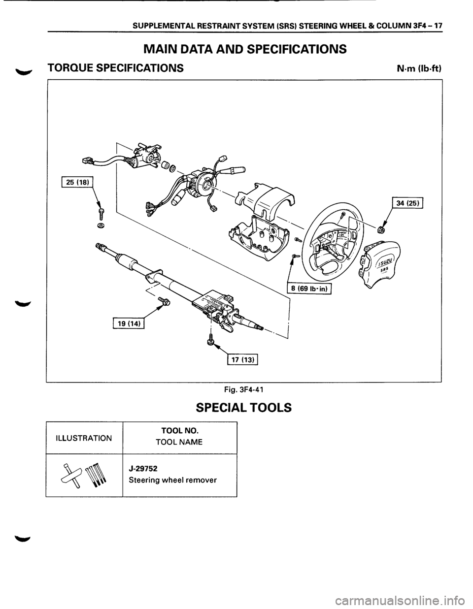
SUPPLEMENTAL RESTRAINT SYSTEM (SRS) STEERING WHEEL & COLUMN 3F4-17
MAIN DATA AND SPECIFICATIONS
TORQUE SPECIFICATIONS
Fig. 3F4-41
SPECIAL TOOLS
TOOL NO.
ILLUSTRATION TOOL
NAME
~~
J-29752
Steering wheel remover
N-m (lb.ft)
Page 229 of 1928
PROPELLER SHAFT 4A-1
SECTION 4A
PROPELLER SHAFT AND AXLE
CONTENTS
Propeller Shaft . . . . . . . . . . . . . . . . . . . . . . . . . . . . . . . . . . . . . . . . . . . . . . . . . . . . . . . . . . . . . . . . . . Section 4A
Rear Axle . . . . . . . . . . . . . . . . . . . . . . . . . . . . . . . . . . . . . . . . . . . . . . . . . . . . . . . . . . . . . . . . . . . . . . . Section 48
Front Driving Axle . . . . . . • . . . . . . . . . . . . . . . . . . . . . . . . . . . . . . . . . . . . . . . . . . . . . . . . . . . . . . . . Section 4C
SECTION 4A
PROPELLER SHAFT
\fl CAUTION:
VI When fasteners are removed, always reinstall them at the same location from which they were removed. If a
fastener needs
to be replaced, use the correct part number fastener for that application. If the correct part
number fastener is
not available, a fastener of equal size and strength (or stronger) may be used. Fasteners
that are
not reused, and those requiring thread locking compound, will be called out. The correct torque
values must be used when installing fasteners that require torque. If the above conditions are not followed, •
parts or system damage could result.
CONTENTS
General Description . . . . . . . . . . . . . . . . . . . . . 4A-1
On-Vehicle Service . . . . . . . . . . . . . . . . . . . . . 4A-2
Rear
Propeller Shaft . . . . . . . . . . . . . . . . . . 4A-2
Front Propeller Shaft . . . . . . . . . . . . . . . . . . 4A-3
Unit Repair ............................ 4A-4
Rear
Propeller Shaft . . . . . . . . . . . . . . . . . . 4A-4
Universal Joint (Rear Propeller Shaft) .... 4A-5
Front Propeller Shaft .................. 4A-8
Universal Joint (Front Propeller Shaft) ... 4A-9
Main Data and Specifications ............ 4A-12
General Specifications ................ 4A-12
Torque Specifications ................ 4A-13
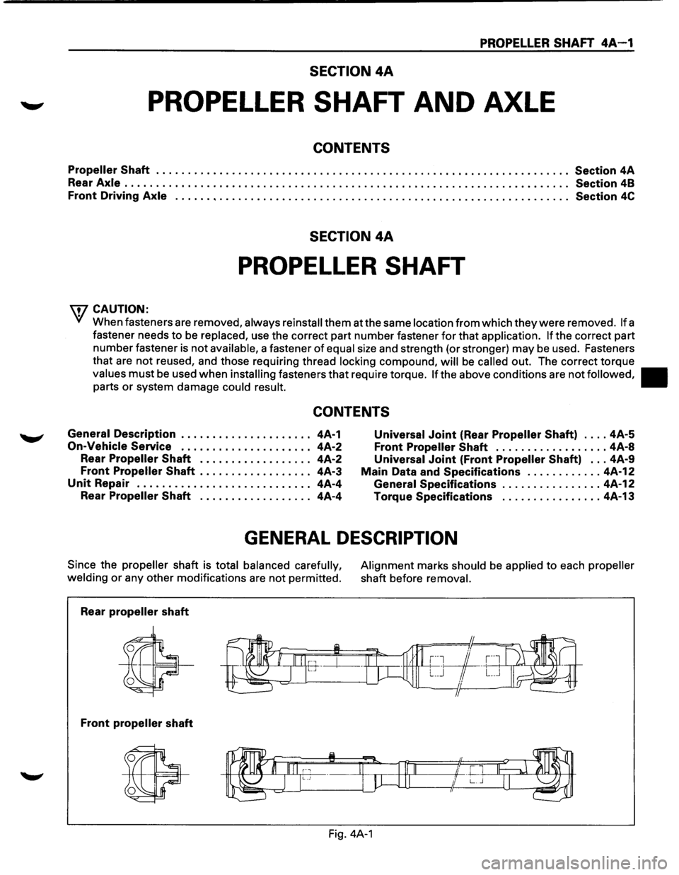
GENERAL DESCRIPTION
Since the propeller shaft is total balanced carefully,
welding
or any other modifications are not permitted.
Rear
propeller shaft
Front propeller shaft
Alignment marks should be applied to each propeller
shaft before removal.
Fig. 4A-1
Page 230 of 1928
4A-2 PROPELLER SHAFT
ON-VEHICLE SERVICE
Preparation:
• Jack up the vehicle and support it on the chassis •
stands. Gear
shift
lever should be placed in neutral
position and parking brake released.
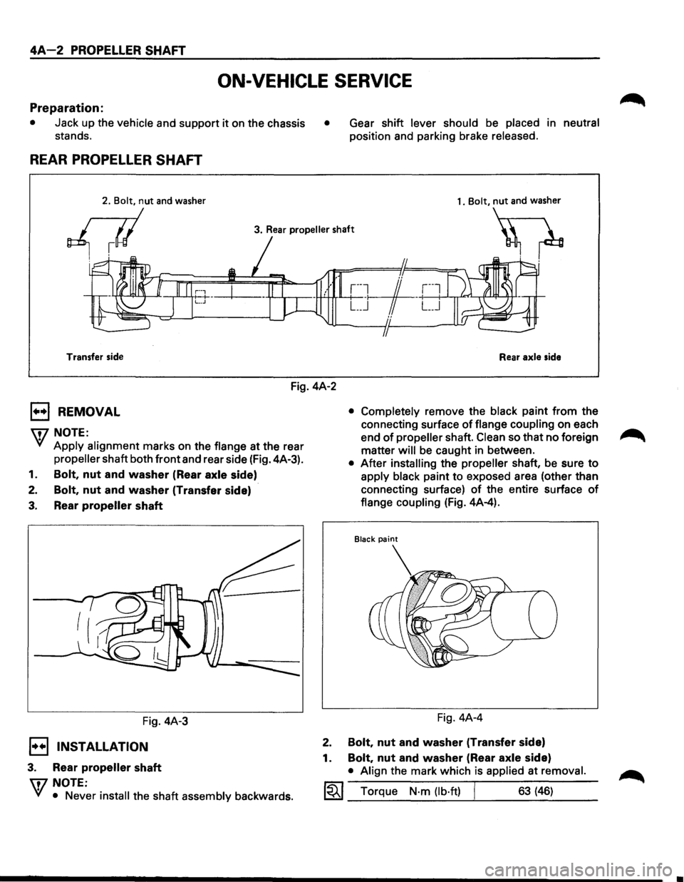
REAR PROPELLER SHAFT
1. Bolt, nut and washer
3. Rear propeller shaft
~
Transfer side
Rear axle side
Fig. 4A-2
B REMOVAL
\fl NOTE:
VI Apply alignment marks on the flange at the rear
propeller shaft both front and rear side (Fig. 4A-3).
1. Bolt, nut and washer (Rear axle side)
2. Bolt, nut and washer (Transfer side)
3. Rear propeller shaft
Fig. 4A-3
1••1 INSTALLATION
3. Rear propeller shaft
\flNOTE:
VI • Never install the shaft assembly backwards.
• Completely remove the black paint from the
connecting surface
of flange coupling on each
end
of propeller shaft. Clean so that no foreign ~
matter will be caught in between.
• After installing the propeller shaft, be sure to
apply black paint to exposed area (other than
connecting surface)
of the entire surface of
flange coupling (Fig. 4A-4).
Fig. 4A-4
2. Bolt, nut and washer (Transfer side)
1.
Bolt, nut and washer (Rear axle side)
• Align the mark which is applied at removal.
~~~ Torque N·m (lb·ft) I 63 (46)
•
Page 241 of 1928
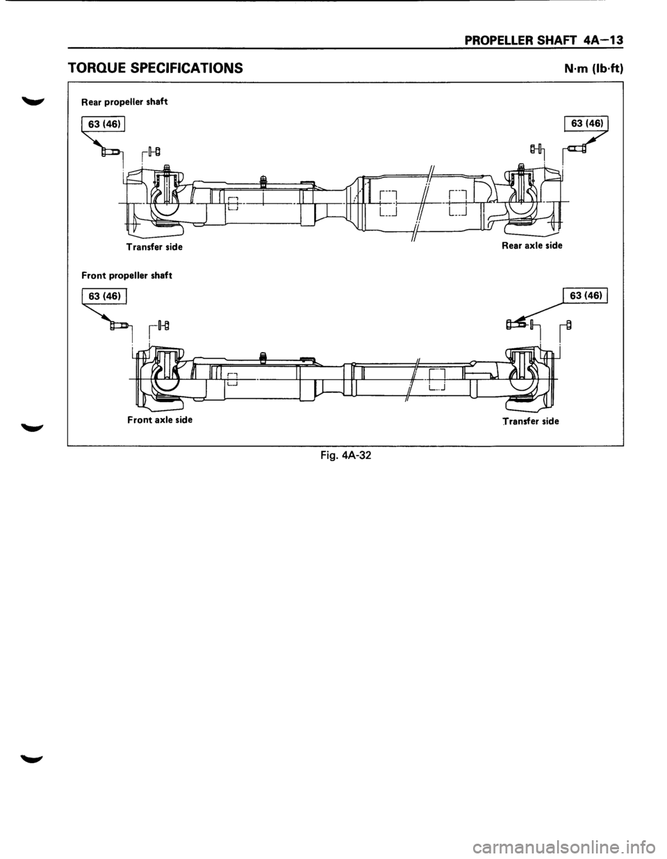
PROPELLER SHAFT 4A-13
TORQUE SPECIFICATIONS N·m (lb·ft)
....._., Rear propeller shaft
Transfer side
Front propeller shaft
~
Front axle side
Transfer side
Fig. 4A-32
Page 243 of 1928
REAR AXLE 48-1
SECTION 48
REAR AXLE
\V CAUTION:
When fasteners are removed, always reinstall them at the same location from which they were removed.
If a fastener needs to be replaced, use the correct part number fastener for that application. If the correct
part number fastener is not available, a fastener of equal size and strength (or stronger) may be used.
Fasteners
that are not reused, and those requiring thread locking compound, will be called out. The
correct
torque values must be used when installing fasteners that require torque. If the above conditions
are not followed, parts or system damage could result.
CONTENTS
General Description . . . . . . . . . . . . . . . . . . . . 48-1
Diagnosis of Rear
Axle Noise . .
. . . . . . . . . . 48-3
On-Vehicle Service ..................... 48-4
Axle Housing . .
. . . . . . . . . . . . . . . . . . . . . 48-4
Axle Shaft . .
. . . . . . . . . . . . . . . . . . . . . . . . 48-7
Pinion
Oil Seal . .
. . . . . . . . . . . . . . . . . . . .
48-10
Differential Assembly
. .
. . . . . . . . . . . . . . 48-11 Unit
Repair . . . . . . . . . . . . . . . . . . . . . . . . . . . 48-13
Differential Assembly . .
. . . . . . . . . . . . . .
48-13 Differential Cage Assembly . . . . . . . . . . . . 48-23
Limited
Slip Differential . .
. . . . . . . . . . . . 48-27
Main Data and Specifications . . . . . . . . . . . . 48-33
General Specifications . .
. . . . . . . . . . . . . . 48-33
Torque Specifications
................ 48-34
Special Tools ......................... 48-35
GENERAL DESCRIPTION
The rear axle assembly is of the semi-floating type in
which the vehicle weight is carried on the axle
housing (Fig. 48-1).
The center
line of the pinion gear is below the center
line of the ring gear (hypoid drive).
All parts necessary to transmit power from the
propeller shaft to the rear wheels are enclosed in a
banjo type axle housing.
The 8.7 inch ring gear rear axle uses a conventional
ring and
pinion gear set to transmit the driving force
of the engine to the rear wheels. This gear set transfers
this driving force at a 90 degree angle from the
propeller shaft to the drive shafts. The
axle shafts
are supported at the wheel end of the
shaft by a roller bearing.
The
pinion gear is supported by two tapered roller
bearings. The pinion depth is set by a shim pack
located between the gear end of the pinion and the
roller bearing that is pressed onto the pinion. The
pinion bearing preload is set by crushing a collapsible
spacer between the bearings in the axle housing.
Page 248 of 1928
48-6 REAR AXLE
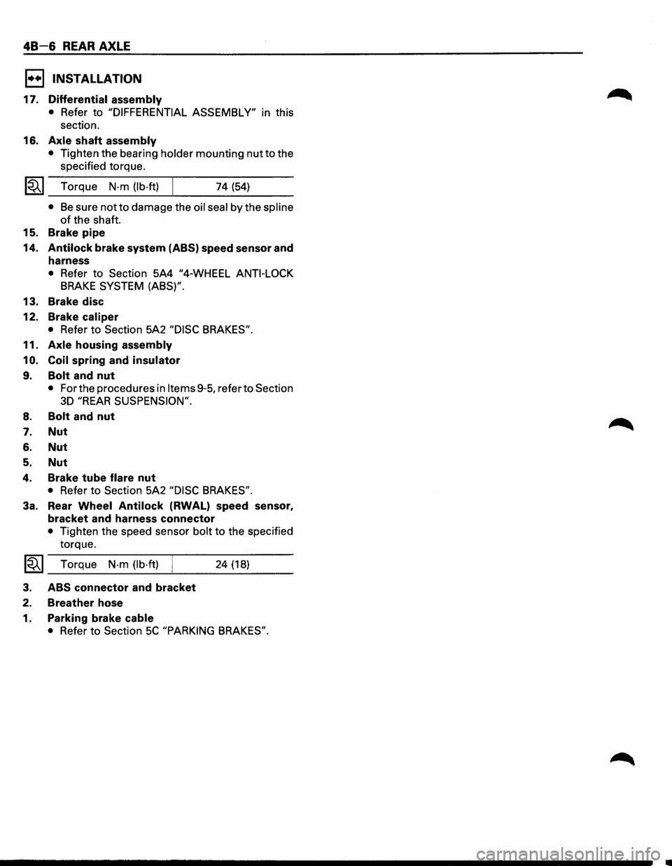
1••1 INSTALLATION
17. Differential assembly
• Refer to "DIFFERENTIAL ASSEMBLY" in this
section.
16.
Axle shaft assembly
• Tighten the bearing holder mounting nut to the
specified torque.
~~~ Torque N·m (lb·ft) 74 (54)
• Be sure not to damage the oil seal by the spline
of the shaft.
15. Brake
pipe
14. Antilock brake system (ABS) speed sensor and
harness
• Refer to Section 5A4 "4-WHEEL ANTI-LOCK
BRAKE SYSTEM (ABS)".
13. Brake disc
12. Brake
caliper
• Refer to Section 5A2 "DISC BRAKES".
11.
Axle housing assembly
10. Coil spring and insulator
9. Bolt and nut
• For the procedures in Items 9-5, refer to Section
3D "REAR SUSPENSION".
8. Bolt and nut
7. Nut
6. Nut
5. Nut
4. Brake tube flare nut
• Refer to Section 5A2 "DISC BRAKES".
3a. Rear Wheel Antilock (RWAL) speed sensor,
bracket and harness connector
• Tighten the speed sensor bolt to the specified
torque.
1~1 Torque N-m (lb·ft) j 24 (18)
3. ABS connector and bracket
2. Breather hose
1. Parking brake cable
• Refer to Section 5C "PARKING BRAKES".
Page 251 of 1928
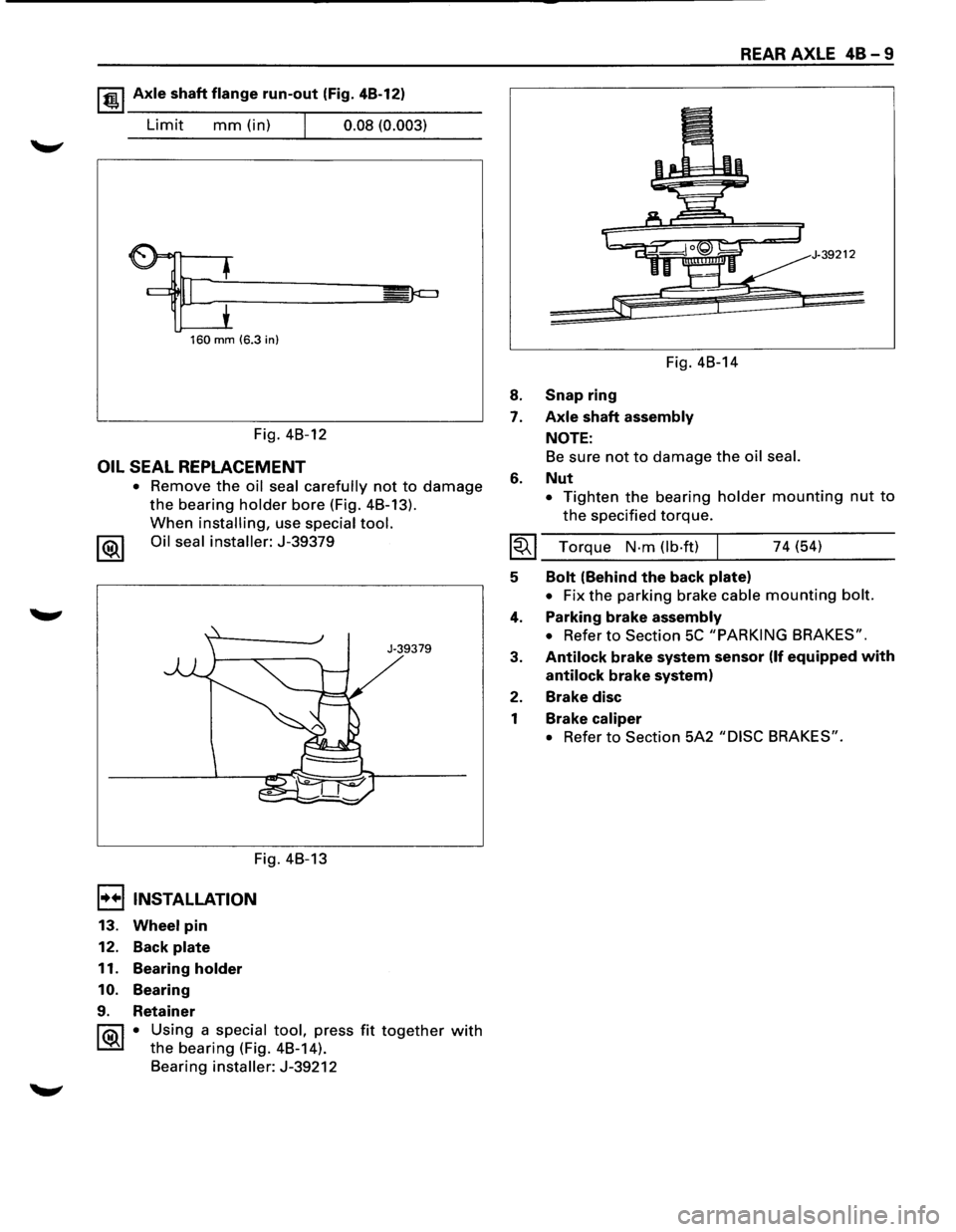
1 t!!.l Axle shaft flange run-out (Fig. 4B-12)
Limit mm (in) I 0.08 (0.003)
160 mm (6.3 in)
Fig. 4B-12
OIL SEAL REPLACEMENT
• Remove the oil seal carefully not to damage
the bearing holder bore (Fig. 4B-13).
When installing, use special tool.
1®1 Oil seal installer: J-39379
Fig. 4B-13
I••IINSTALLATION
13. Wheel pin
12. Back plate
11. Bearing holder
10. Bearing
9. Retainer
J-39379
1 ®I • Using a special tool, press fit together with
the bearing (Fig. 4B-14).
Bearing
installer: J-39212
8.
7.
6.
Fig. 4B-14
Snap ring
Axle shaft assembly
NOTE:
REAR AXLE 48-9
39212
Be sure not to damage the oil seal.
Nut
• Tighten the bearing holder mounting nut to
the specified torque.
I~I ___ T_o_rq_u_e __ N_·_m_(_lb_·f_t)~l _____ 7_4_(~5~4) ____ ___
5
4.
3.
2.
1
Bolt (Behind the back plate)
• Fix the parking brake cable mounting bolt.
Parking brake assembly
• Refer to Section 5C "PARKING BRAKES".
Antilock brake system sensor (If equipped with
antilock brake system)
Brake disc
Brake caliper
• Refer to Section 5A2 "DISC BRAKES".
Page 254 of 1928
48-12 REAR AXLE
1. Parking brake cable
• Remove the parking brake cable fastening clip
and disconnect the equalizer section. Refer
to
Section SC "PARKING BRAKES".
2. Nut
• Remove the bearing holder fixing nuts.
3. Axle shaft assembly
• Be sure notto damage the oil seal by axle shaft.
4.
Bolt and nut
• Remove differential carrier mounting bolts and
nuts.
5. Differential assembly
1••1 INSTALLATION
5. Differential assembly
• Clean the contact surfaces of the axle and
differential carrier.
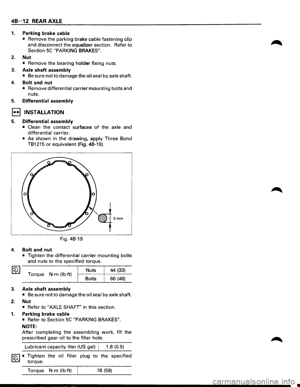
• As shown in the drawing, apply Three Bond
TB1215
or equivalent (Fig. 4B-19).
3mm
Fig. 4B-19
4. Bolt and nut
• Tighten the differential carrier mounting bolts
and nuts
to the specified torque.
Torque
N·m (lb·ft) Bolts Nuts
44
(33)
66 (48)
3. Axle shaft assembly
• Be sure notto damage
the oil seal by axle shaft.
2. Nut
• Refer to "AXLE SHAFT' in this section.
1. Parking brake cable
• Refer to Section 5C "PARKING BRAKES".
NOTE:
After completing the assembling work, fill the
prescribed gear
oil to the filler hole.
~·
Lubricant capacity liter (US gal) j 1.8 (0.5)
Tighten the oil filler plug to the specified
torque.
Torque
N·m (lb·ft) 78 (58)
Page 258 of 1928
48 -16 REAR AXLE
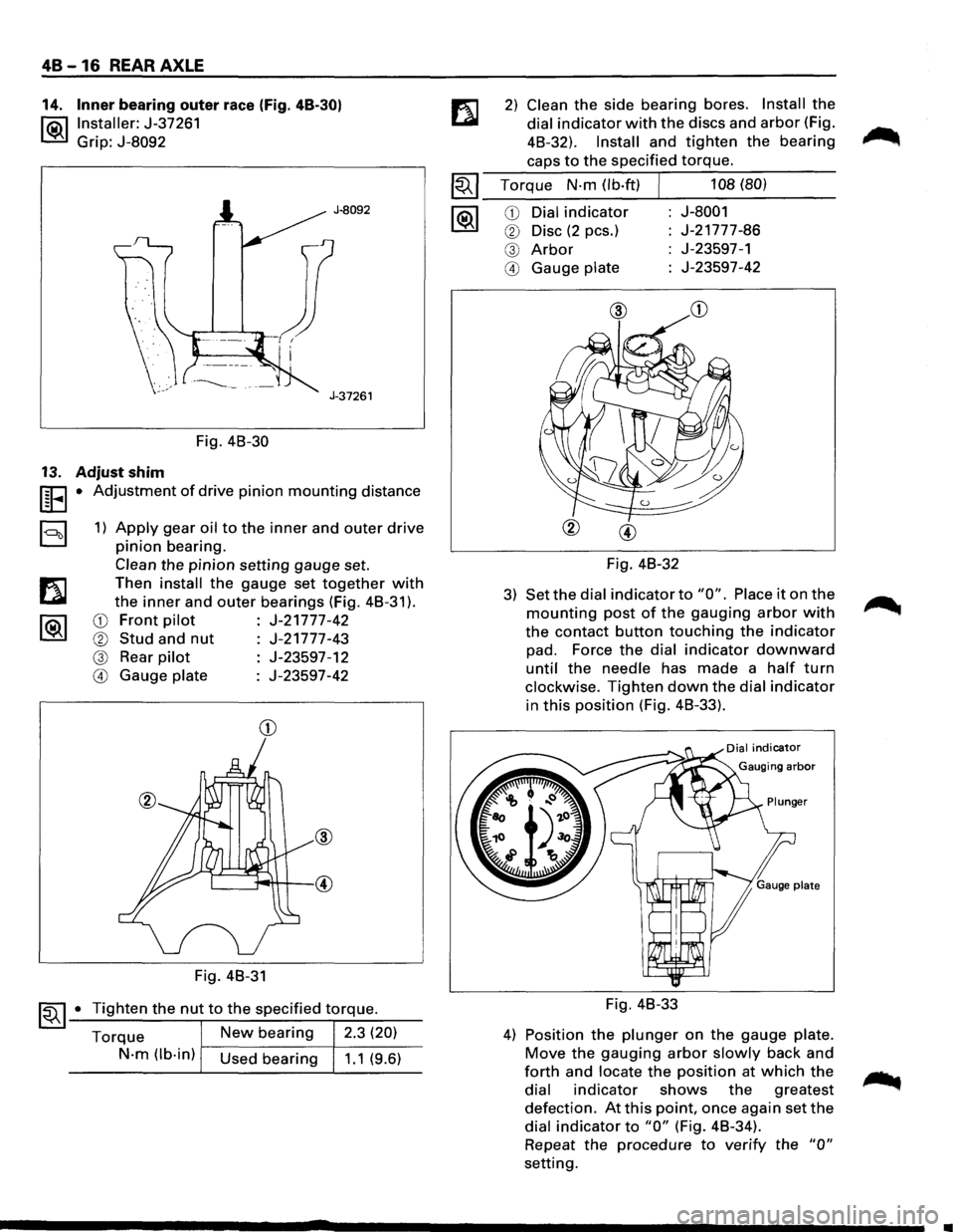
14. Inner bearing outer race (Fig. 48-30)
l®.llnstaller: J-37261
Grip: J-8092
J-8092
J-37261
Fig. 48-30
13. Adjust shim
UEI • Adjustment of drive pinion mounting distance
a 1) Apply gear oil to the inner and outer drive
pinion bearing.
Clean the pinion setting gauge set.
Then
install the gauge set together with
the inner and outer bearings (Fig. 48-31 ).
CD Front pilot J-21777-42
® Stud and nut J-21777-43
@ Rear pilot J-23597-12
@ Gauge plate J-23597-42
CD
Fig. 48-31
~~ 1-•-T_i..::..g_h_te_n_t_h_e_n_u...,t_t_o_t_h_e_s..:..p_e_c_if_ie_d_t-\
.-o_rq....:..._ue_. __
Torque New bearing 2.3 (20)
N-m (lb-in) Used bearing 1.1 (9.6)
2) Clean the side bearing bores. Install the
dial indicator with the discs and arbor (Fig.
48-32).
Install and tighten the bearing
caps to the specified torque.
~~~ Torque N-m (lb·ft) J 108 (80)
--------~----------1®.1 CD Dial indicator J-8001
® Disc (2 pes.) J-21777-86
@ Arbor J-23597-1
@ Gauge plate J-23597-42
Fig. 48-32
3) Set the dial indicator to "0". Place it on the
mounting post of the gauging arbor with
the contact button touching the indicator
pad. Force the dial indicator downward
until the needle has made a half turn
clockwise. Tighten down the dial indicator
in this position (Fig. 48-33).
Fig. 48-33
4) Position the plunger on the gauge plate.
Move the gauging arbor slowly back and
forth and locate the position at which the
dial indicator shows the greatest
defection. At this point, once again set the
dial indicator to "0" (Fig. 48-34).
Repeat
the procedure to verify the "0"
setting.
•
Page 261 of 1928
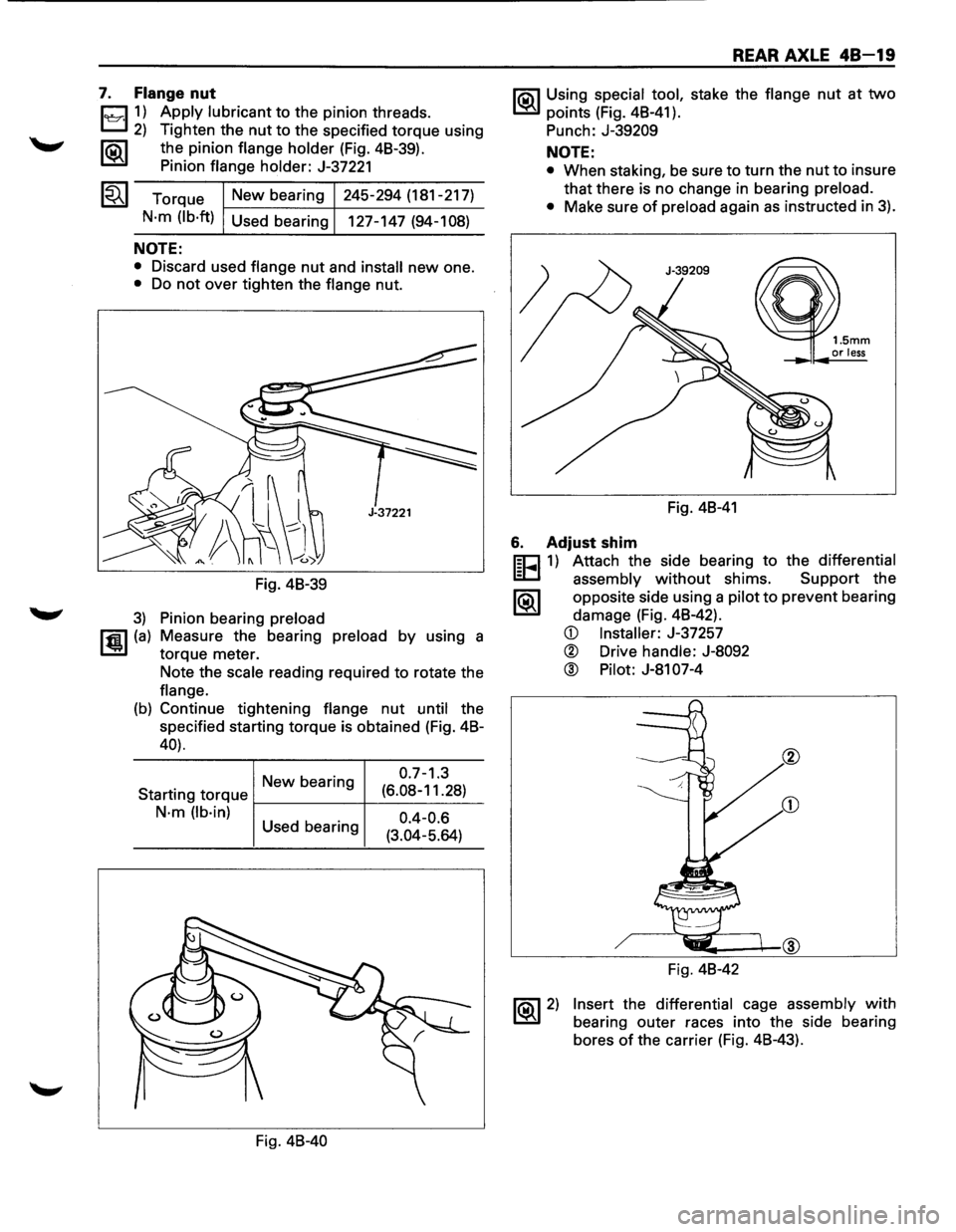
7. Flange nut
1~11) Apply lubricant to the pinion threads.
2) Tighten the nut to the specified torque using
1®.1 the pinion flange holder (Fig. 48-39).
Pinion
flange holder: J-37221
Torque
New bearing 245-294
(181-217)
N·m (lb·ft) Used bearing
127-147 (94-108)
NOTE:
• Discard used flange nut and install new one.
• Do not over tighten the flange nut.
Fig. 48-39
3) Pinion bearing preload
rfiil (a) Measure the bearing preload by using a
1..!!.1 torque meter.
Note the
scale reading required to rotate the
flange.
(b) Continue tightening flange nut until the
specified starting torque is obtained (Fig. 48-
40).
New bearing 0
·7
-1
·3
Starting
torque f-------+--(6_._08_-_1_1_.2_8_) _
N·m (lb·in) 0.4-0.6 Used bearing
(3.04-5.64)
Fig.
48-40
REAR AXLE 48-19
1'?.3\1 Using special tool, stake the flange nut at two
~points (Fig. 48-41).
Punch:
J-39209
NOTE:
• When staking, be sure to turn the nut to insure
that there is no change in bearing
preload.
•
Make sure of preload again as instructed in 3).
Fig. 48-41
6. Adjust shim
m=J 1) Attach the side bearing to the differential
~ assembly without shims. Support the
1®.1 opposite side using a pilot to prevent bearing
damage (Fig. 48-42).
~ 2)
CD Installer: J-37257
® Drive handle: J-8092
® Pilot: J-81 07-4
Fig. 48-42
Insert the differential cage assembly with
bearing outer races into the side bearing
bores
of the carrier (Fig. 48-43).