torque ISUZU TROOPER 1995 Workshop Manual
[x] Cancel search | Manufacturer: ISUZU, Model Year: 1995, Model line: TROOPER, Model: ISUZU TROOPER 1995Pages: 1928
Page 354 of 1928
5A2-4 DISC BRAKES
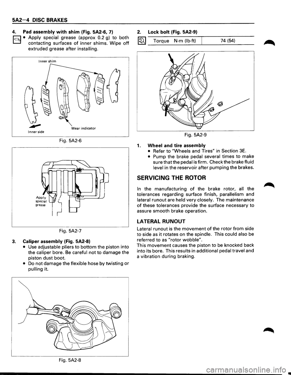
4. Pad assembly with shim (Fig. 5A2-6, 7)
1-c::~t:.l• Apply ~pecial grease (approx 0.2 g) to both
contactmg surfaces
of inner shims. Wipe off
extruded grease after installing.
Inner shim
Wear
indicator Inner side
Fig. 5A2-6
Fig. 5A2-7
3. Caliper assembly (Fig. 5A2-8)
• Use adjustable pliers to bottom the piston into
the
caliper bore. Be careful not to damage the
piston
dust boot.
• Do not damage the flexible hose by twisting or
pulling it.
Fig. 5A2-8
2. Lock bolt (Fig. 5A2-9)
1«1 Torque N·m (lb·ft) 74 (54)
Fig. 5A2-9
1. Wheel and tire assembly
• Refer to "Wheels and Tires" in Section 3E.
• Pump the brake pedal several times to make
sure that the pedal is firm. Check the brake fluid
level in the reservoir after pumping the brakes.
SERVICING THE ROTOR
In the manufacturing of the brake rotor, all the
tolerances regarding surface finish,
parallelism and
lateral
runout are held very closely. The maintenance
of these tolerances provide the surface necessary to
assure smooth brake operation.
LATERAL RUNOUT
Lateral runout is the movement of the rotor from side
to side as it rotates on the spindle. This could also be
referred
to as "rotor wobble".
This movement causes the piston to be knocked back
into its bore. This results in
additional pedal travel and
a vibration during braking.
Page 357 of 1928
ll .. •l INSPECTION AND REPAIR
Make necessary parts replacement, if wear, damage,
"'-"' corrosion or any other abnormal conditions are found
through inspection.
Check the following parts;
• Rotor
• Cylinder body
• Cylinder bore
• Piston
•
Guide bolt, Lock bolt
•
Support bracket
NOTE:
The piston seal, boot ring and dust boot are to be
replaced each time the caliper is overhauled. Discard
these used rubber parts and
replace with new ones.
l*!•l REASSEMBLY
9. Caliper body
8. Bleeder with cap
~~~ Torque N·m (lb·in) 8 (69)
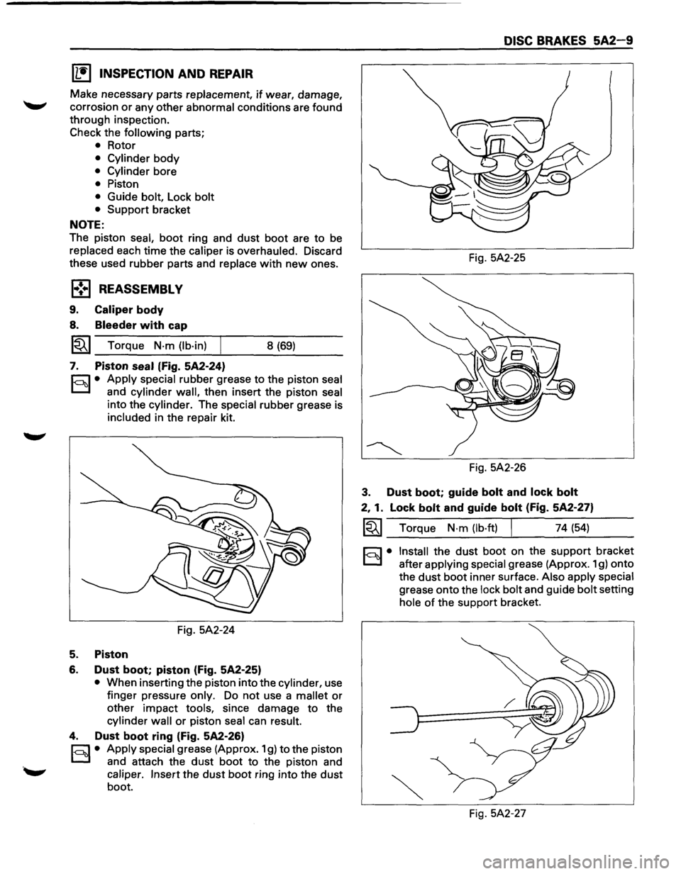
7. Piston seal (Fig. 5A2-24)
r.:;::'1 • Apply special rubber grease to the piston seal
0 and cylinder wall, then insert the piston seal
into the cylinder. The special rubber grease is
included in the repair kit.
Fig. 5A2-24
5. Piston
6. Dust boot; piston (Fig. 5A2-25)
• When inserting the piston into the cylinder, use
finger pressure
only. Do not use a mallet or
other impact tools, since damage to the
cylinder wall or piston seal can result.
4. Dust boot ring (Fig. 5A2-26)
r;::;:] • Apply special grease (Approx. 1 g) to the piston
0 and attach the dust boot to the piston and
caliper. Insert the dust boot ring into the dust
boot.
DISC BRAKES 5A2-9
Fig. 5A2-25
Fig. 5A2-26
3. Dust boot; guide bolt and lock bolt
2, 1. Lock bolt and guide bolt (Fig. 5A2-27)
~~~ Torque N·m (lb·ft) I 74 (54)
§)• Install the dust boot on the support bracket
after
applying special grease (Approx. 1 g) onto
the
dust boot inner surface. Also apply special
grease onto the lock bolt and guide bolt setting
hole of the support bracket.
Fig. 5A2-27
Page 359 of 1928
3. Caliper assembly
• Support the caliper assembly so that the brake
hose is
not stretched or damaged.
4. Pad assembly with shim
5. Clip
l·u·l INSTALLATION
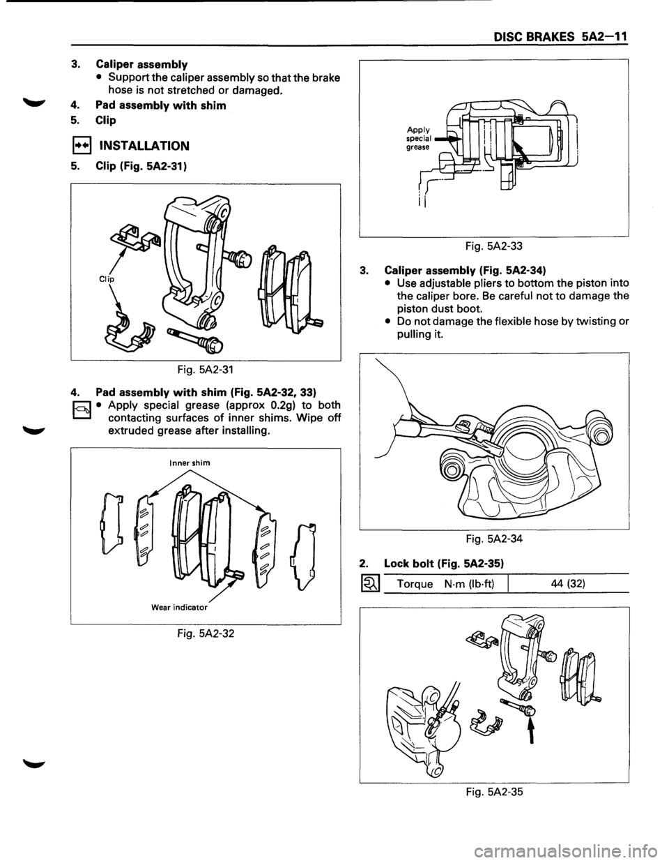
5. Clip (Fig. 5A2-31)
~ Clip
Fig. 5A2-31
4. Pad assembly with shim (Fig. 5A2-32, 33)
c=;:] • Apply special grease (approx 0.2g) to both
D contacting surfaces of inner shims. Wipe off
extruded grease after installing.
Inner shim
0
Wear indicator
Fig. 5A2-32
DISC BRAKES 5A2-11
Fig. 5A2-33
3. Caliper assembly (Fig. 5A2-34)
• Use adjustable pliers to bottom the piston into
the
caliper bore. Be careful not to damage the
piston dust boot.
• Do not damage the flexible hose by twisting or
pulling it.
Fig. 5A2-34
2. Lock bolt (Fig. 5A2-35)
~~~ Torque N·m (lb·ft) I
Fig. 5A2-35 44
(32)
Page 363 of 1928
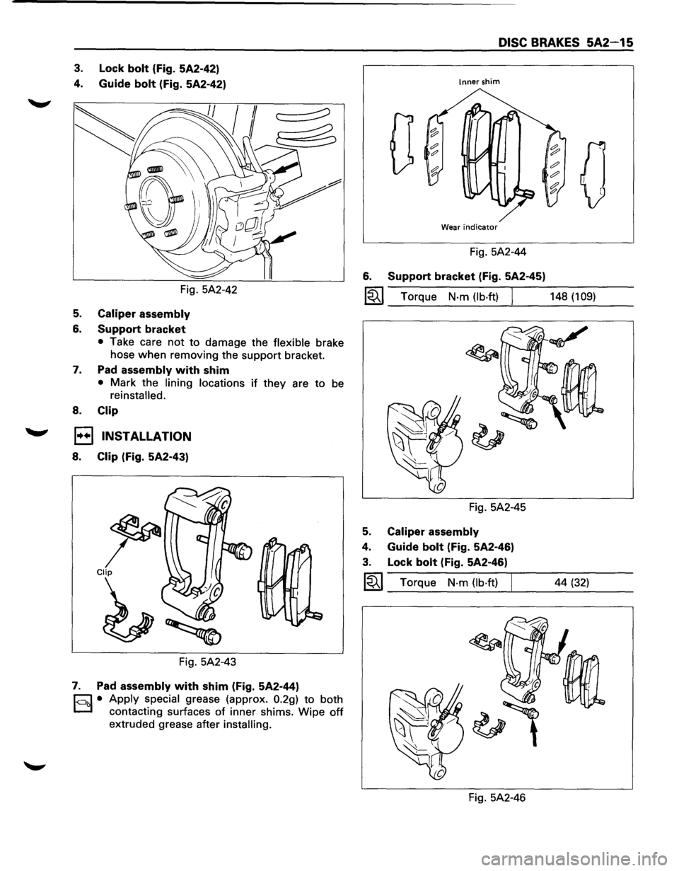
3. Lock bolt (Fig. 5A2-42)
4.
Guide bolt (Fig. 5A2-42)
Fig. 5A2-42
5. Caliper assembly
6. Support bracket
• Take care not to damage the flexible brake
hose
when removing the support bracket.
7. Pad assembly with shim
• Mark the lining locations if they are to be
reinstalled.
8. Clip
1••1 INSTALLATION
8. Clip (Fig. 5A2-43)
Fig. 5A2-43
7. Pad assembly with shim (Fig. 5A2-44)
r;::;:] • Apply special grease (approx. 0.2g) to both
D contacting surfaces of inner shims. Wipe off
extruded grease after installing.
DISC BRAKES 5A2-15
Inner shim
0
Wear indicator
Fig. 5A2-44
6. Support bracket (Fig. 5A2-45)
~~~ Torque N·m (lb·ft) I 148 (109)
Fig. 5A2-45
5. Caliper assembly
4. Guide bolt (Fig. 5A2-46)
3. Lock bolt (Fig. 5A2-46)
~~~ Torque N·m (lb·ft) I
Fig. 5A2-46
44 (32)
Page 364 of 1928
5A2-16 DISC BRAKES
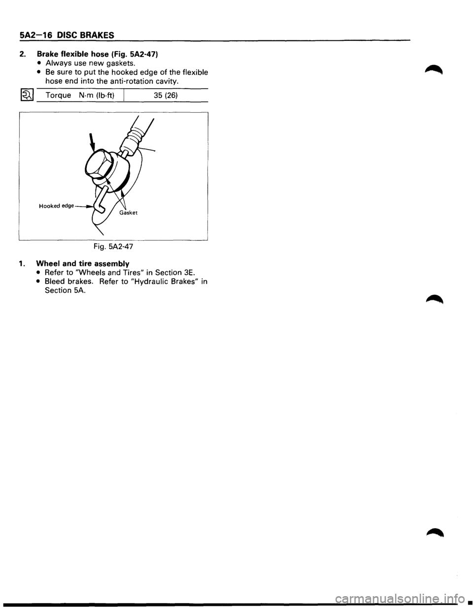
2. Brake flexible hose (Fig. 5A2-47)
• Always use new gaskets.
• Be sure to put the hooked edge of the flexible
hose end into the anti-rotation cavity.
~~~ Torque N-m (lb·ft) 35 (26)
Hooked edge
Fig. 5A2-47
1. Wheel and tire assembly
• Refer to "Wheels and Tires" in Section 3E.
• Bleed brakes. Refer to "Hydraulic Brakes" in
Section 5A.
•
Page 366 of 1928
![ISUZU TROOPER 1995 Workshop Manual 5A2-18 DISC BRAKES
(1!] INSPECTION AND REPAIR
Make necessary parts replacement, if wear, damage,
corrosion
or any other abnormal conditions are found
through inspection.
Check the
followi](/img/61/57183/w960_57183-365.png "ISUZU TROOPER 1995 Workshop Manual 5A2-18 DISC BRAKES
(1!] INSPECTION AND REPAIR
Make necessary parts replacement, if wear, damage,
corrosion
or any other abnormal conditions are found
through inspection.
Check the
followi")
5A2-18 DISC BRAKES
(1!] INSPECTION AND REPAIR
Make necessary parts replacement, if wear, damage,
corrosion
or any other abnormal conditions are found
through inspection.
Check the
following parts;
• Rotor
• Cylinder body
• Cylinder bore
• Piston
• Slide
pin
• Support bracket
NOTE:
The piston dust seal and dust boot are to be replaced
each time the caliper is overhauled. Discard these
used rubber parts and
replace with new ones.
1•! .. 1 REASSEMBLY
9. Caliper body
8. Bleeder with cap
1~1 Torque N·m (lb·in) 8 (69)
7. Piston seal (Fig. 5A2-51)
r:::;] • Apply special rubber grease to the piston seal
D and cylinder wall, then insert the piston seal
into the cylinder. The special rubber grease is
included in the repair kit.
Fig. 5A2-51
5. Piston
6. Dust boot; piston (Fig. 5A2-52)
• When inserting the piston into the cylinder, use
finger pressure
only. Do not use a mallet or
other impact tools, since damage to the
cylinder wall or piston seal can result.
4. Dust boot ring (Fig. 5A2-53)
r:::;] • Apply special grease (Approx. 1 g) to the piston
D and attach the dust boot to the piston and
caliper. Insert the dust boot ring into the dust
boot. Fig.
5A2-52
Fig. 5A2-53
3. Dust boot (Fig. 5A2-54)
r:::;] • Install the dust boot on the support bracket
D after applying special grease (Approx. 1 g) onto
the dust
boot inner surface. Also apply special
grease onto the lock bolt and guide bolt setting
hole of the support bracket.
2. Lock bolt
1. Guide bolt
Fig. 5A2-54
~~~ Torque N-m (lb·ft) 44 (32)
•
Page 367 of 1928
DISC BRAKES 5A2-19
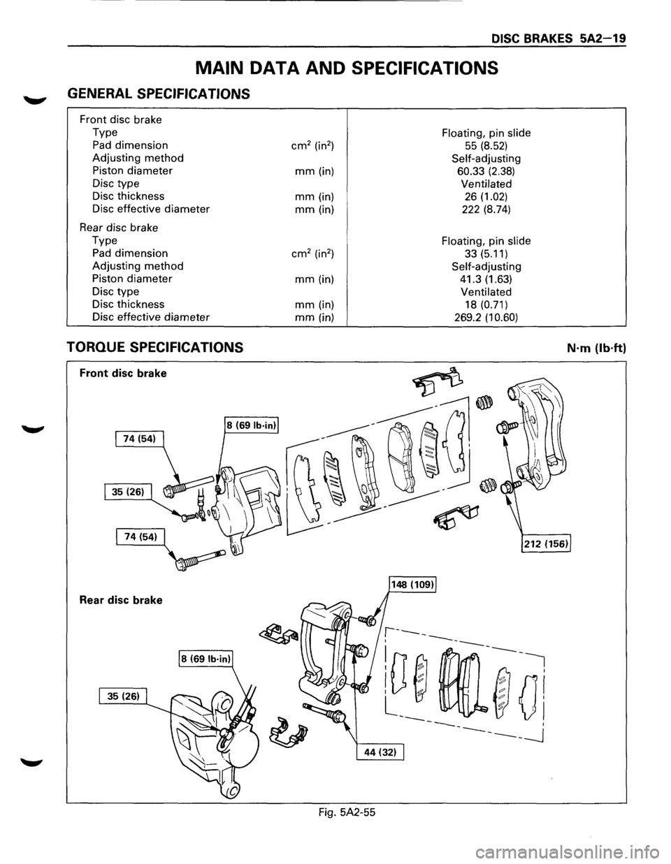
MAIN DATA AND SPECIFICATIONS
~ GENERAL SPECIFICATIONS
Front disc brake
Type
Floating, pin slide
Pad dimension cm2 (in2 ) 55 (8.52)
Adjusting method Self-adjusting
Piston
diameter mm (in) 60.33 (2.38)
Disc type Ventilated
Disc thickness mm (in) 26 (1.02)
Disc effective diameter
mm(in) 222 (8.74)
Rear disc brake
Type
Floating, pin slide
Pad dimension cm2 (in2
) 33(5.11)
Adjusting
method Self-adjusting
Piston
diameter mm (in) 41.3 (1.63)
Disc
type Ventilated
Disc thickness mm (in) 18 (0.71)
Disc effective
diameter mm (in) 269.2 (1 0.60)
TORQUE SPECIFICATIONS N·m (lb·ft)
Front disc brake
Rear disc brake
Fig. 5A2-55
Page 369 of 1928
REAR WHEEL ANTILOCK BRAKE SYSTEM 5A3-1
SECTION 5A3
REAR WHEEL ANTILOCK BRAKE SYSTEM
(RWAL}
w CAUTION:
• All brake attaching fasteners are an important attaching part in that they could affect performance of vital
parts and systems, and/or could result in major repair expense. They must be replaced with one of the same
part
number or with an equivalent part if replacement becomes necessary. Do not use replacement parts of
lesser quality or substitute design. Torque values must be used as specified during reassembly to assure
proper retention of these parts.
CONTENTS
Introduction . . . . . . . . . . . . . . . . . . . . . . . . . 5A3· 1
General Description . .
. . . . . . . . . . . . . . .
5A3· 1
Rear
Wheel Antilock (RWAL) Control
Parts Location . .
. . . . . . . . . . . . . . . . .
5A3· 5
System Diagram . .
. . . . . . . . . . . . . . . . . . . .
5A3· 6
Rear
Wheel Antilock (RWAL) System
Diagnostics . .
. . . . . . . . . . . . . . . . . . . . . .
5A3· 7
On-Vehicle Service . .
. . . . . . . . . . . . . . . . .
5A3·38
RWAL Electronic Brake Control
Module (EBCM) Replacement ....... 5A3-38
Antilock
(Isolation/Dump) Valve
Replacement ..................... 5A3-39
Speed Sensor Replacement
.......... 5A3-40
Main Data and Specifications ........... 5A3-41
Torque Specifications
............... 5A3-41
INTRODUCTION
This section deals with the complete diagnosis and
services
for vehicles equipped with rear wheel
antilock.
For service information regarding all other
components
of the brake system, refer to "Hydraulic
Brakes"
(Sec. SA), "Brake Booster System" (Sec. SA 1)
or "Disc Brakes" (Sec. SA2) of this Manual.
GENERAL DESCRIPTION
The rear wheel anti lock system (RWAL) is designed to
reduce rear wheel lock-up during a severe brake
application,
thus maintaining rear end stability. The
system functions
by regulating the rear hydraulic
brake line pressure. The pressure regulation is
accomplished
by an anti lock valve which is located on
the
front right side of engine room. The anti lock valve
is made up of two valves, a dump valve which releases
pressure into an accumulator and an isolation valve
which maintains rear brake pressure. The valve is
controlled
by a microcomputer which is part of the
Electronic Brake Control Module (EBCM). The
EBCM is mounted at the
front of the center
console. Under severe brake application, as pressure
is
applied to the brake pedal, the EBCM is designed to
permit the valve to do one of three functions or a
combination
of all three. The EBCM will allow the valve
to either maintain the same amount of hydraulic
pressure, release hydraulic pressure through the
dump valve into the accumulator or increase the
pressure by
pulsing the isolation valve.
The EBCM operates by receiving signals from the
speed sensor (which
is located in the differential
carrier), combination
valve and the brake light switch.
The RWAL system is connected
to the RWAL indicator
light located on the dash. An indication of the RWAL
operation and a
bulb check is performed each time the
ignition is turned
"ON". The indicator light will remain
on
for about two seconds. A RWAL system
malfunction is indicated if the RWAL indicator light
stays on, or comes on during driving. To determine the
specific
trouble, refer to "RWAL System Diagnostics"
in this section.
Page 406 of 1928
5A3-38 REAR WHEEL ANTILOCK BRAKE SYSTEM
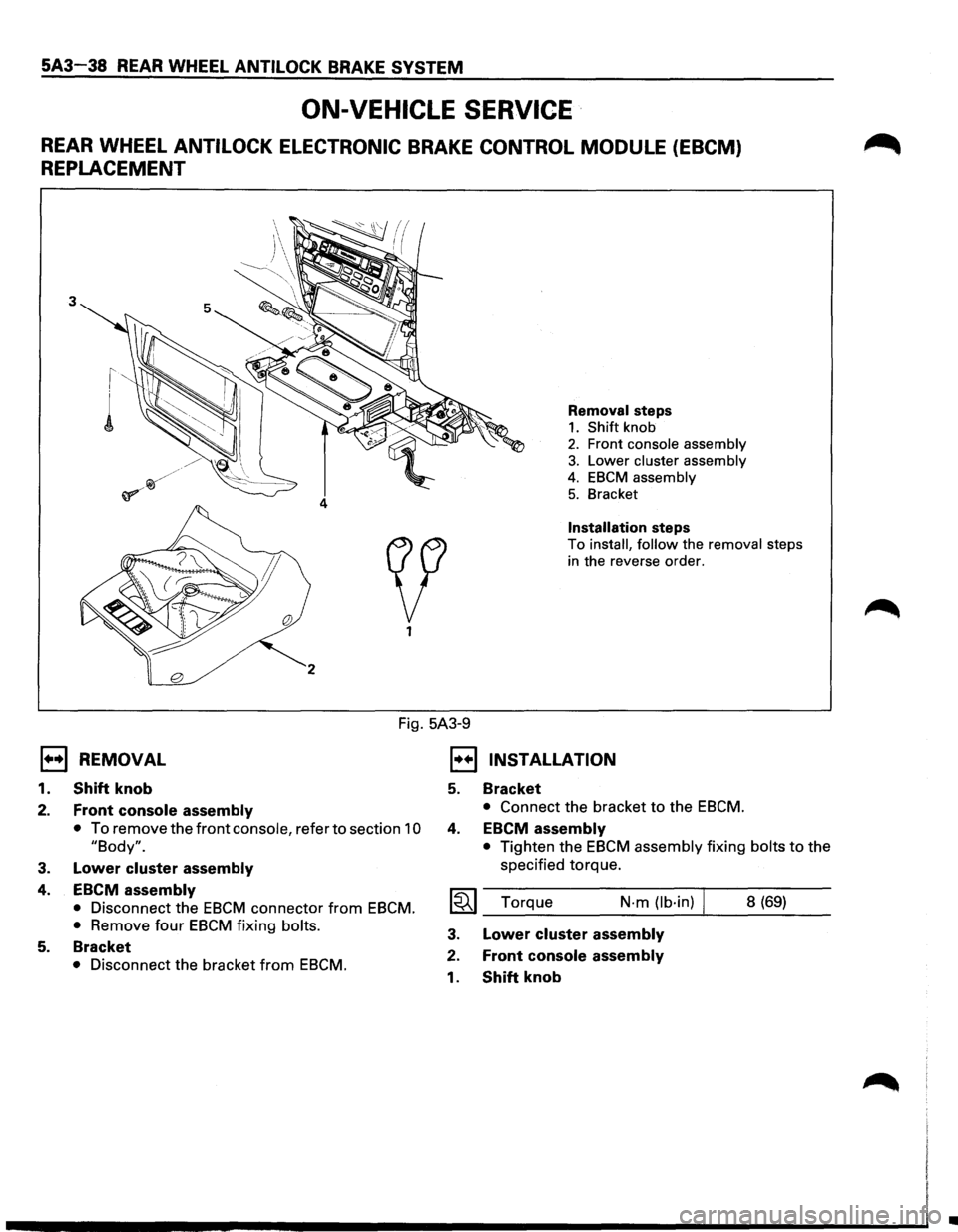
ON-VEHICLE SERVICE ·
REAR WHEEL ANTILOCK ELECTRONIC BRAKE CONTROL MODULE (EBCM)
REPLACEMENT
3
Removal steps
1. Shift knob
2. Front console assembly
3. Lower cluster assembly
4. EBCM assembly
5. Bracket
Installation steps
To install, follow the removal steps
in the reverse order.
Fig. 5A3-9
E) REMOVAL
1.
2.
3.
4.
5.
Shift knob
Front console assembly
• To remove the front console, refer to section 10
"Body".
Lower cluster assembly
EBCM assembly
• Disconnect the EBCM connector from EBCM.
•
Remove four EBCM fixing bolts.
Bracket
• Disconnect the bracket from EBCM.
1•+1 INSTALLATION
5.
4.
Bracket
• Connect the bracket to the EBCM.
EBCM assembly
• Tighten the EBCM assembly fixing bolts to the
specified torque.
I~I_T_o_rq_u_e ____ N·_m_(lb_·i_n_) ...... 1 __ 8_(6_9_) __
3.
2.
1.
Lower cluster assembly
Front console assembly
Shift knob
•
Page 407 of 1928
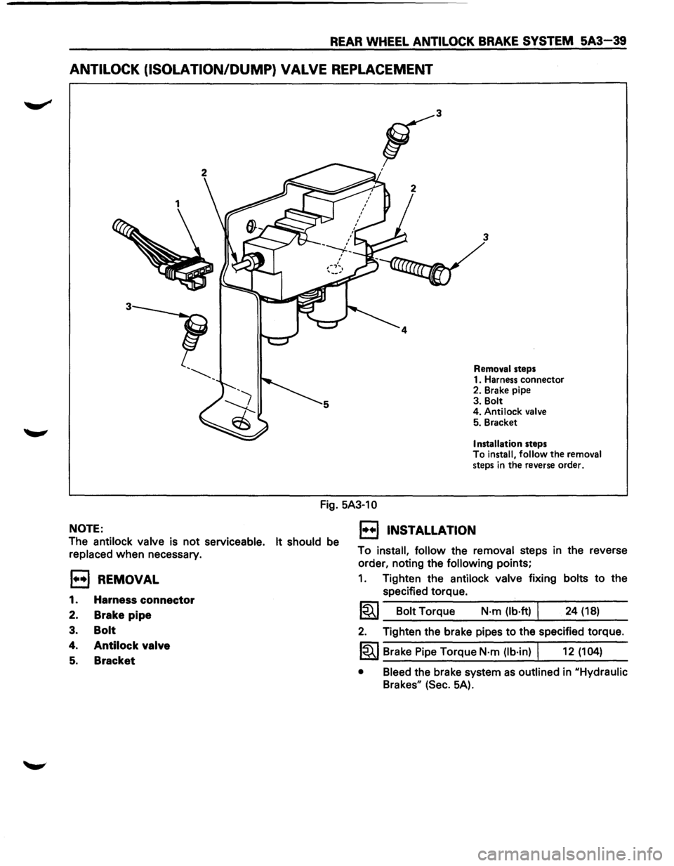
REAR WHEEL ANTILOCK BRAKE SYSTEM 5A3-39
ANTILOCK (ISOLATION/DUMP) VALVE REPLACEMENT
3
Removal steps
1. Harness connector
2. Brake pipe
3. Bolt
4. Antilock
valve 5. Bracket
Installation steps
To install, follow the removal
steps in the reverse order.
Fig. 5A3-10
NOTE:
The antilock valve is not serviceable. It should be
replaced when necessary.
EJ REMOVAL
1. Harness connector
2. Brake pipe
3. Bolt
4. Antilock valve
5. Bracket
1••1 INSTALLATION
To install, follow the removal steps in the reverse
order, noting the
following points;
1. Tighten the antilock valve fixing bolts to the
specified torque.
1~1 Bolt Torque N·m (lb·ft) I 24 (18)
2. Tighten the brake pipes to the specified torque.
1~1 Brake Pipe Torque N·m (lb·in) I 12 (104)
• Bleed the brake system as outlined in uHydraulic
Brakesu (Sec. 5A).