torque ISUZU TROOPER 1995 Workshop Manual
[x] Cancel search | Manufacturer: ISUZU, Model Year: 1995, Model line: TROOPER, Model: ISUZU TROOPER 1995Pages: 1928
Page 531 of 1928
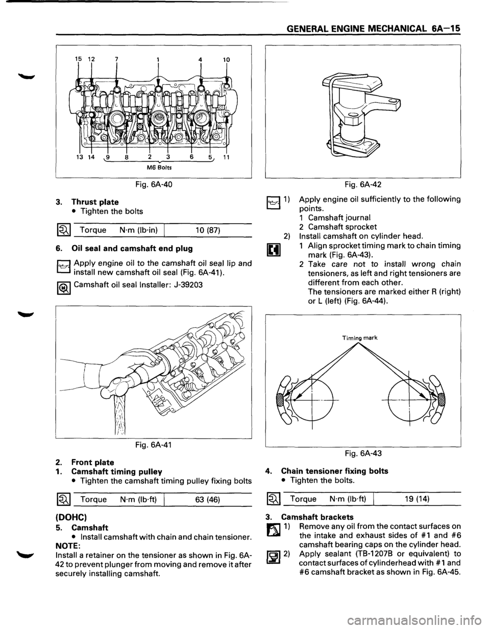
15 12 7 4 10
13 14 -.:9:...._--=8 __ =-2 ---..-....::3:.__ _ _:6:___:::..~5 11
M6 Bolts
Fig. 6A-40
3. Thrust plate
• Tighten the bolts
~~~ Torque N·m (lb·in) 10 (87)
6. Oil
seal and camshaft end plug
1~·1 Apply engine oil to the camshaft oil seal lip and
install new camshaft oil seal (Fig. 6A-41).
1®-1 Camshaft oil seal Installer: J-39203
Fig. 6A-41
2. Front plate
1. Camshaft timing pulley
• Tighten the camshaft timing pulley fixing bolts
1~1 Torque N·m (lb·ft) 63 (46)
(DOHC)
5. Camshaft
• Install camshaft with chain and chain tensioner.
NOTE:
Install a retainer on the tensioner as shown in Fig. 6A-
42 to prevent plunger from moving and remove it after
securely
installing camshaft.
GENERAL ENGINE MECHANICAL 6A-15
~1)
2)
u
Fig. 6A-42
Apply engine oil sufficiently to the following
points.
1 Camshaft journal
2 Camshaft sprocket
Install camshaft on cylinder head.
1 Align sprocket
timing mark to chain timing
mark (Fig. 6A-43).
2 Take care
not to install wrong chain
tensioners,
as left and right tensioners are
different from each other.
The tensioners are marked either R (right)
or L (left) (Fig. 6A-44).
Timing mark
Fig. 6A-43
4. Chain tensioner fixing bolts
• Tighten the bolts.
1~1 Torque N·m (lb·ft) 19 (14)
3. Camshaft brackets
m 1) Remove any oil from the contact surfaces on
Lll the intake and exhaust sides of #1 and #6
camshaft bearing caps on the cylinder head.
~~~2) Apply sealant (TB-12078 or equivalent) to
contact surfaces of cylinderhead with # 1 and
#6 camshaft bracket as shown in Fig. 6A-45.
Page 532 of 1928
6A-16 GENERAL ENGINE MECHANICAL
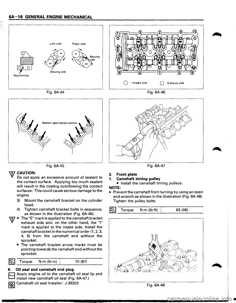
Left side Right side
Moving side Positioning
Q : Intake side 0 : Exhaust side
Fig. 6A-44 Fig. 6A-46
Sealant application points
Fig. 6A-45
7 CAUTION:
'VI Do not apply an excessive amount of sealant to
the contact surface. Applying too much sealant
will result
in the coating overflowing the contact
surfaces. This
could cause serious damage to the
engine.
3)
4)
w·
•
Mount the camshaft bracket on the cylinder
head.
Tighten camshaft bracket
bolts in sequence,
as shown in the illustration (Fig. 6A-46).
The
"E" mark is applied to the camshaft bracket
exhaust side and, on the other hand, the
"I"
mark is applied to the intake side. Install the
camshaft bracket in the
numerical order (1, 2, 3,
4, 6) from the camshaft end without the
sprocket.
The camshaft bracket
arrow marks must be
pointing towards the camshaft end
without the
sprocket.
~~~ Torque N·m (lb·in) f 10 (87)
6. Oil seal and camshaft end plug
CJ Apply engine oil to th~ camsh~ft oil seal lip and
L.::::J install new camshaft oil seal (F1g. 6A-47.)
1®..1 Camshaft oil seal Installer: J-39203
Fig. 6A-47
2. Front plate
1. Camshaft timing pulley
• Install
the camshaft timing pulleys.
NOTE:
• Prevent the camshaft from turning by using an open
end wrench
as shown in the illustration (Fig. 6A-48).
Tighten the
pulley bolts.
~~~ Torque N·m (lb·ft) 63 (46)
Fig. 6A-48
•
Page 534 of 1928
6A-18 GENERAL ENGINE MECHANICAL
Oil
Clearance
Standard
0.005-0.045
(0.0002-0.0018)
Fig. 6A-51
mm (in)
Limit
0.2 (0.0079)
Replace the rocker arm and/or rocker shaft if the
measured
oil clearance exceeds the specified limit.
1~1 Runout
1. Place the rocker shaft on V-blocks (Fig. 6A-52).
2. Set the dial indicator.
3. Slowly rotate the rocker shaft and measure the
run out.
If the run out is in excess of the specified limit, the
rocker shaft
must be replaced.
mm (in)
Limit o.2 (o.oo79)
I
Fig. 6A-52
Rocker arm
wcAUTION
' Visually inspect the rocker arm and replace them
if damage or abnormal wear is evident.
l•!•l REASSEMBLY
7. Rocker arm
l'e::r.l • Apply a light coat of engine oil to the rocker arm
shafts.
Rocker arm shafts are different, so care
should
be taken when reinstalling rocker shafts (Fig.
6A-55).
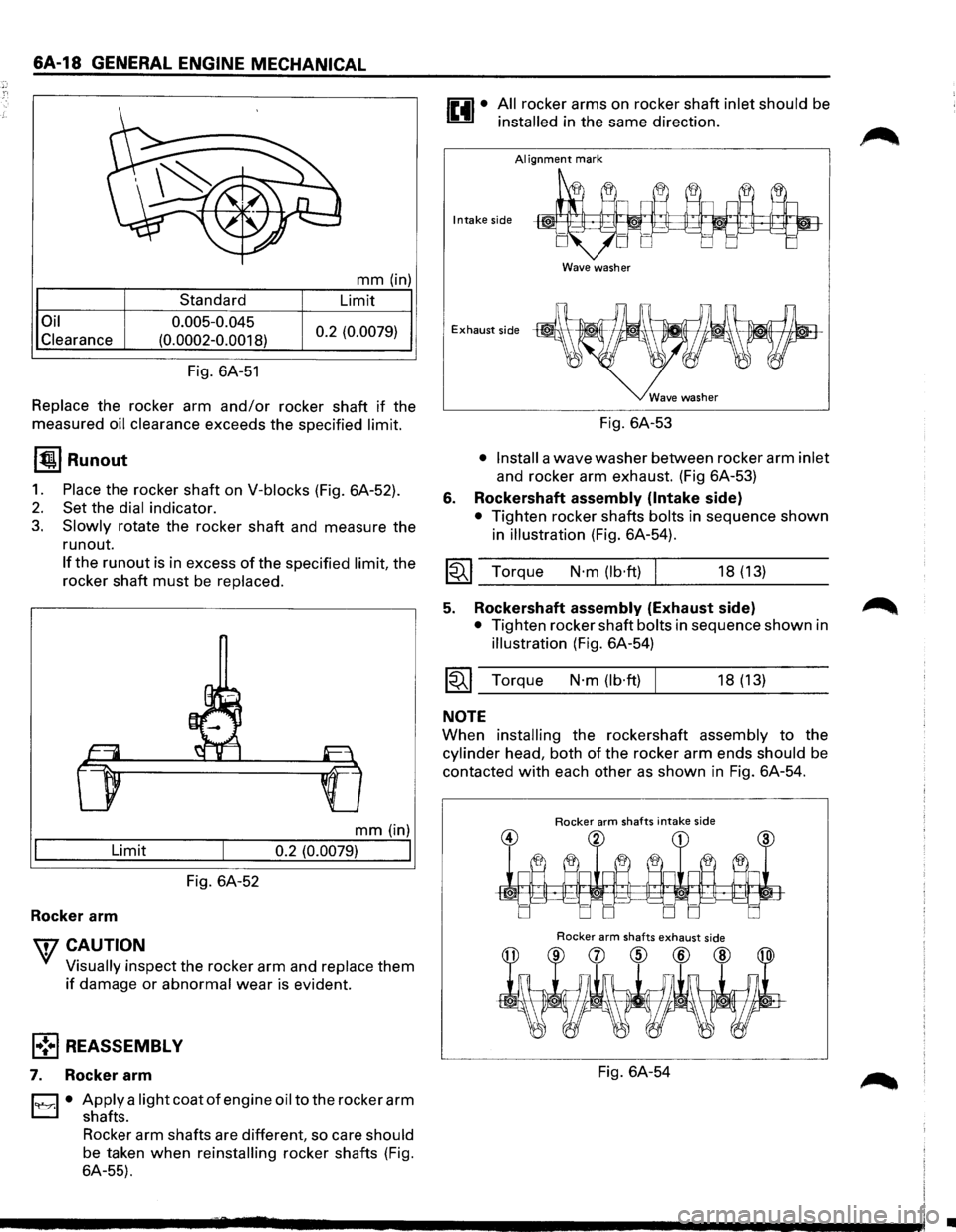
All rocker arms on rocker shaft inlet should be
installed in the same direction.
AI ignment mark
Intake side
Wave washer
Exhaust side
6.
Fig. 6A-53
• Install a wave washer between rocker arm inlet
and rocker arm exhaust. (Fig 6A-53)
Rockershaft assembly (Intake side)
• Tighten rocker shafts bolts in sequence shown
in
illustration (Fig. 6A-54).
I~I __ To_r_q_ue ___ N_·_m_(_lb_·ft_)~l ______ 18_(_1_3) ____ _
5. Rockershaft assembly (Exhaust side) ~
• Tighten rocker shaft bolts in sequence shown in
illustration (Fig. 6A-54)
~~~ Torque N·m (lb·ft) I 18 (13)
NOTE
When installing the rockershaft assembly to the
cylinder head, both of the rocker arm ends should be
contacted
with each other as shown in Fig. 6A-54.
Rocker arm shafts intake side
Rocker arm shafts exhaust side
Fig. 6A-54
•
Page 537 of 1928
Body and gears
The pump assembly must be replaced if one or
more of the conditions below is discovered
during inspection.
• Badly worn or damaged driven gear guide.
• Badly worn driving gear drive face.
• Badly scratched or scored body sliding face or
driven gear.
• Badly worn or damaged gear teeth.
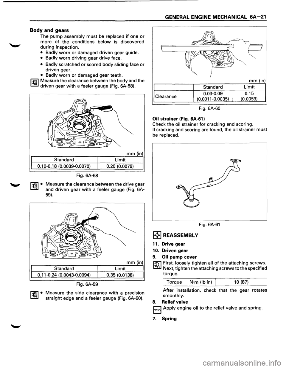
~ Measure the clearance between the body and the
I..!:.J driven gear with a feeler gauge (Fig. 6A-58).
mm (in)
Standard
Limit
0.10-0.18 (0.0039-0.0070) 0.20 (0.0079)
~·
Fig. 6A-58
Measure the
clearance between the drive gear
and driven gear
with a feeler gauge (Fig. 6A-
59).
mm (in)
Standard Limit
0.11-0.24
(0.0043-0.0094) 0.35 (0.0138)
Fig. 6A-59
ltm.l• Measure the side clearance with a precision
straight edge and a
feeler gauge (Fig. 6A-60).
GENERAL ENGINE MECHANICAL 6A-21
Clearance
Standard
0.03-0.09
(0.0011-0.0035)
Fig. 6A-60
Oil strainer (Fig. 6A-61)
mm (in)
Limit
0.15
(0.0059)
Check the
oil strainer for cracking and scoring.
If cracking and scoring are found, the oil strainer must
be replaced.
Fig. 6A-61
l•!•l REASSEMBLY
11. Drive gear
1
0. Driven gear
9. Oil pump cover
~ First, loosely tighten all of the attaching screws.
~ Next, tighten the attaching screws to the specified
torque.
Torque
N·m (lb·in) ) 10 (87)
After installation, check that the gear rotates
smoothly.
8. Relief valve
I~J Apply engine oil to the relief valve and spring.
7. Spring
Page 538 of 1928
.r Ti
6A-22 GENERAL ENGINE MECHANICAL
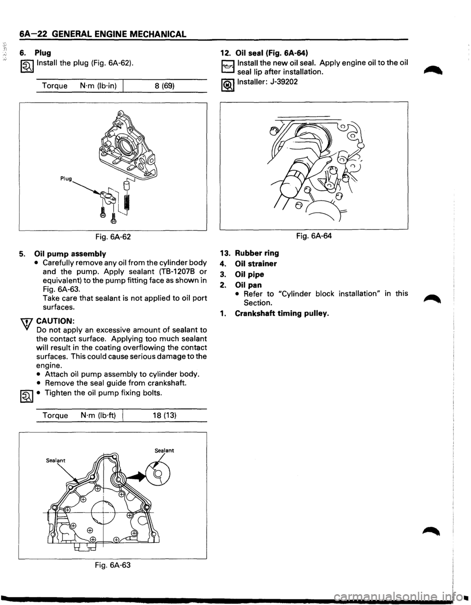
6. Plug
~~~Install the plug (Fig. 6A-62).
Torque
N·m (lb·in) 8 (69)
Fig. 6A-62
5. Oil pump assembly
• Carefully
remove any oil from the cylinder body
and the pump. Apply sealant (TB-12078 or
equivalent) to the pump fitting face as shown in
Fig. 6A-63.
Take care that sealant is
not applied to oil port
surfaces.
\fl CAUTION:
VI Do not apply an excessive amount of sealant to
the contact surface. Applying
too much sealant
will result in the coating overflowing the contact
surfaces. This could cause serious damage
to the
engine.
• Attach oil pump assembly to cylinder body.
• Remove the seal guide from crankshaft.
~~~ • Tighten the oil pump fixing bolts.
Torque
N·m (lb·ft) 18 (13)
Fig. 6A-63 12.
Oil
seal (Fig. 6A-64)
Cl Install the new oil seal. Apply engine oil to the oil
t..:::::::.l seal lip after installation.
~~~Installer: J-39202
13. Rubber ring
4. Oil strainer
3. Oil pipe
2. Oil pan Fig.
6A-64
• Refer to "Cylinder block installation" in this
Section.
1. Crankshaft timing pulley.
..
Page 540 of 1928
6A-24 GENERAL ENGINE MECHANICAL
mm(in)
Standard Limit
0.06-0.24 (0.0023-0.0094) 0.30 (0.0118)
Fig. 6A-66 Fig. 6A-68
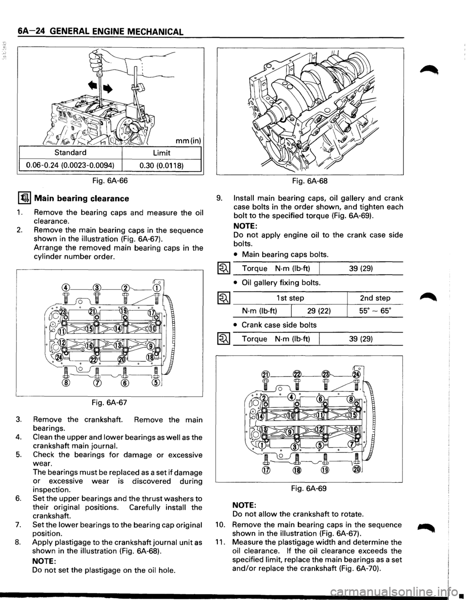
IQI Main bearing clearance
1. Remove the bearing caps and measure the oil
clearance.
2. Remove the main bearing caps in the sequence
shown in the
illustration (Fig. 6A-67).
Arrange the removed main bearing caps in the
cylinder number order.
Fig. 6A-67
3. Remove the crankshaft. Remove the main
bearings.
4. Clean the upper and lower bearings as well as the
crankshaft main
journal.
5. Check the bearings for damage or excessive
wear.
The bearings
must be replaced as a set if damage
or excessive wear is discovered during
inspection.
6. Set the upper bearings and the thrust washers to
their original positions. Carefully install the
crankshaft.
7. Set the lower bearings to the bearing cap original
position.
8. Apply plastigage to the crankshaft journal unit as
shown in the illustration (Fig. 6A-68).
NOTE:
Do not set the plastigage on the oil hole.
9. Install main bearing caps, oil gallery and crank
case
bolts in the order shown, and tighten each
bolt to the specified torque (Fig. 6A-69).
~
~
~
NOTE:
Do not apply engine oil to the crank case side
bolts.
•
Main bearing caps bolts.
Torque N·m (lb·ft) I 39 (29)
• Oil gallery fixing bolts.
1st step 2nd step
N·m (lb·ft) 29 (22) 55°-65°
• Crank case side bolts
Torque N·m (lb·ft) 39 (29)
Fig. 6A-69
NOTE:
Do not allow the crankshaft to rotate.
10. Remove the main bearing caps in the sequence
shown in the
illustration (Fig. 6A-67).
11. Measure the plastigage width and determine the
oil clearance. If the oil clearance exceeds the
specified
limit, replace the main bearings as a set
and/or replace the crankshaft (Fig. 6A-70).
•
Page 543 of 1928
l•!•l REASSEMBL V
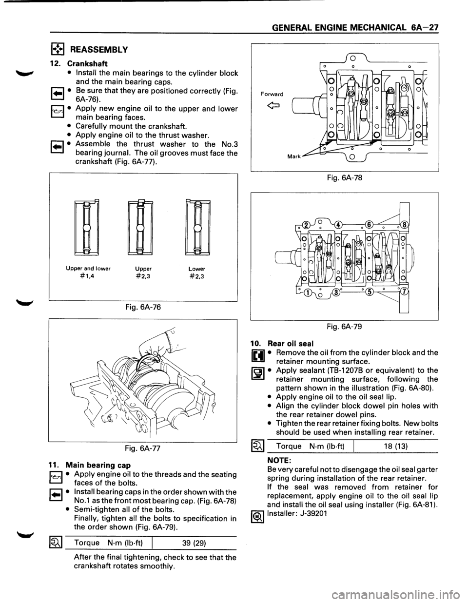
12. Crankshaft
• Install the main bearings to the cylinder block
and the main bearing caps.
1 .. 1• Be sure that they are positioned correctly (Fig.
6A-76).
1~1· Apply new engine oil to the upper and lower
main bearing faces.
• Carefully mount the crankshaft.
• Apply engine oil to the thrust washer.
1 .. 1• Assemble the thrust washer to the No.3
bearing
journal. The oil grooves must face the
crankshaft (Fig. 6A-77).
Upper and lower
#1.4
~
~
IH
t=
Upper
#2,3
Fig. 6A-76
Fig. 6A-77
11. Main bearing cap
Lower
#2,3
B • Apply engine oil to the
threads and the seating
' faces
of the bolts.
r=1 • Install bearing caps in the order shown with the
L:::.l No.1 as the front most bearing cap. (Fig. 6A-78)
• Semi-tighten all of the bolts.
Finally,
tighten all the bolts to specification in
the
order shown (Fig. 6A-79).
1~1 Torque N·m (lb·ft) 39 (29)
After the final tightening, check to see that the
crankshaft rotates
smoothly.
GENERAL ENGINE MECHANICAL 6A-27
Forward
Fig. 6A-78
Fig. 6A-79
10. Rear oil seal
liill • Re~ove the oil_from the cylinder block and the
U retainer mounting surface.
rEil • Apply sealant (TB-1207B or equivalen_t) to the
1.:::!!.1 retainer mounting surface, follow~ng the
pattern shown in the
illustration (Fig. 6A-80).
• Apply engine oil to the oil seal lip.
• Align
the cylinder block dowel pin holes with
the rear retainer dowel pins.
• Tighten the rear retainer fixing bolts. New bolts
should
be used when installing rear retainer.
~~~ Torque N·m (lb·ft) 18 (13)
NOTE:
Be very careful notto disengage the oil seal garter
spring during
installation of the rear retainer.
If the seal was removed from retainer for
replacement, apply engine oil to the oil seal lip
and install the oil seal using installer (Fig. 6A-81).
l®llnstaller: J-39201
Page 544 of 1928
6A-28 GENERAL ENGINE MECHANICAL
Fig. 6A-80
/
Fig. 6A-81
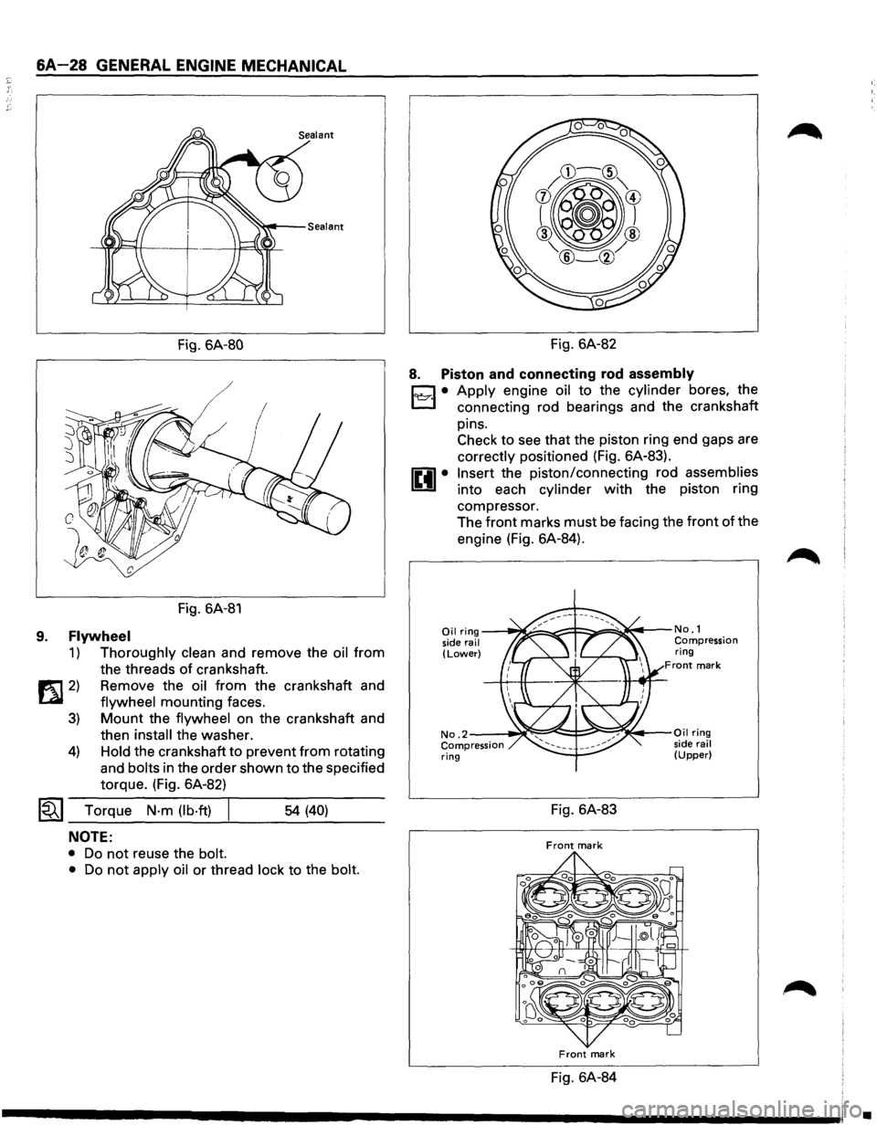
9. Flywheel
1) Thoroughly clean and remove the oil from
the threads
of crankshaft.
1!t1 2) Remove the oil from the crankshaft and
LQI flywheel mounting faces.
3) Mount the flywheel on the crankshaft and
then
install the washer.
4) Hold the crankshaft to prevent from rotating
and
bolts in the order shown to the specified
torque. (Fig. 6A-82)
~~~ Torque N·m (lb·ft) I ___ ___,_ ___ _ 54 (40)
NOTE:
• Do not reuse the bolt.
•
Do not apply oil or thread lock to the bolt.
Fig. 6A-82
8. Piston and connecting rod assembly
D • Apply engine oil to the cylinder bores, the
l:J connecting rod bearings and the crankshaft
pins. Check to see that the piston ring end gaps are
correctly positioned (Fig. 6A-83).
Insert the piston/connecting rod assemblies
into each cylinder with the piston ring
compressor. The
front marks must be facing the front of the
engine (Fig. 6A-84).
Oil ring ---~====-~::F::::::.===~~t---No. 1
side rail Compression (Lower) ring Front mark
No .2--~~:::::=:e!::::!-;::::!!;~~·-Oil ring
Compression side rail ring (Upper)
Fig. 6A-83
Front mark
Front mark
Fig. 6A-84
•
Page 545 of 1928
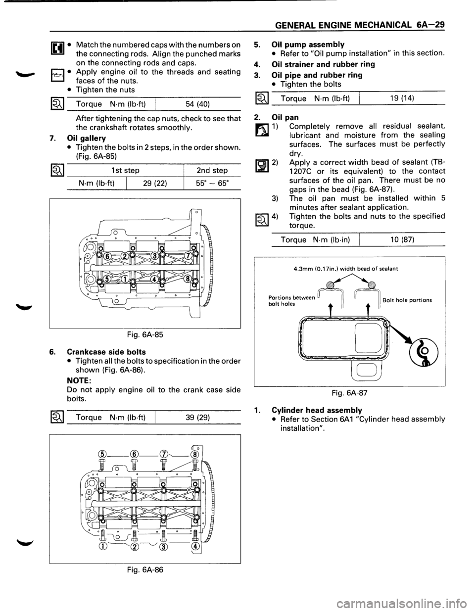
1£41• Match the numbered caps with the numbers on
the connecting rods.
Align the punched marks
on the connecting rods and caps.
1'l:::r.1• Apply engine oil to the threads and seating
faces
of the nuts.
• Tighten the nuts
~~~ Torque N·m (lb·ft) 54 (40)
7.
After tightening the cap nuts, check to see that
the crankshaft rotates smoothly.
Oil gallery
• Tighten the bolts in 2 steps, in the order shown.
(Fig. 6A-85)
1~1 _________ 1_s_t,s_te~p ________ ~ __ 2_n_d __ st_e~p---
N·m (lb·ft) 29 (22) 55° -65°
Fig. 6A-85
6. Crankcase side bolts
• Tighten all the bolts to specification in the order
shown (Fig. 6A-86).
NOTE:
Do not apply engine oil to the crank case side
bolts.
~~~ Torque N·m (lb·ft) 39 (29)
Fig. 6A-86
5.
4.
3.
GENERAL ENGINE MECHANICAL 6A-29
Oil pump assembly
• Refer to "Oil pump installation" in this section.
Oil strainer and rubber ring
Oil pipe and rubber ring
• Tighten the bolts
I~I_T_o_rq...:....u_e_N_·_m_(:.._lb_·ft....:.)---!. ___ 1_9 _(1_4_) __ _
2. Oil pan
m 1) Completely remove all residual sealant,
~ lubricant and moisture from the sealing
surfaces. The surfaces must be perfectly
dry.
~~~2) Apply a correct width bead of sealant (TB-
1207C or its equivalent) to the contact
surfaces
of the oil pan. There must be no
gaps in the bead (Fig. 6A-87).
3) The oil pan must be installed within 5
minutes after
sealant application.
~~~4) Tighten the bolts and nuts to the specified
torque.
Torque
N-m (lb-in) 10 (87)
D
Fig. 6A-87
1. Cylinder head assembly
• Refer to Section 6A
1 "Cylinder head assembly
installation".
Page 549 of 1928
3. Insert the new pin into the piston and rotate
it.
If the pin rotates smoothly with no
backlash, the clearance is normal. If there is
backlash or roughness, measure the
clearance. If the clearance exceeds the
specified
limit, the piston must be replaced.
mm (in)
Standard Limit
Clearance 0.007-0.020
0.040
(0.0003-0.0008) (0.0016)
Connecting rods
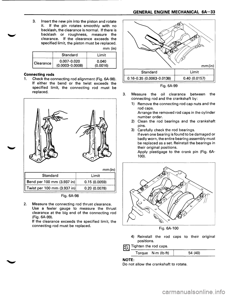
1. Check the connecting rod alignment (Fig. 6A-98).
If either the bend or the twist exceeds the
specified
limit, the connecting rod must be
replaced.
mm(in)
Standard
Limit
Bend per
100 mm (3.937 in)
0.15 (0.0059)
Twist per 100 mm (3.937 in) 0.20 (0.0078)
Fig. 6A-98
2. Measure the connecting rod thrust clearance.
Use a feeler gauge to measure the thrust
clearance at the big end of the connecting rod
(Fig. 6A-99).
If the clearance exceeds the specified limit, the
connecting rod
must be replaced.
3.
GENERAL ENGINE MECHANICAL 6A-33
mm(in)
Standard Limit
0.16-0.35
(0.0063-0.0138) 0.40
(0.0157)
Fig. 6A-99
Measure the
oil clearance between the
connecting rod and the crankshaft by:
1) Remove the connecting rod cap nuts and the
rod caps.
Arrange the removed rod caps in the
cylinder
number order.
2) Clean the rod bearings and the crankshaft
pins.
3) Carefully check the rod bearings.
If even one bearing is found to be damaged or
badly worn, the entire bearing assembly must
be replaced as a set. Reinstall the bearings in
their
original positions.
Apply plastigage to the crank pin (Fig. 6A-
100).
Fig. 6A-100
4) Reinstall the rod caps to their original
positions.
~~~ Tighten the rod caps.
Torque
N·m (lb·ft) 54 (40)
NOTE:
Do not allow the crankshaft to rotate.