sensor ISUZU TROOPER 1995 User Guide
[x] Cancel search | Manufacturer: ISUZU, Model Year: 1995, Model line: TROOPER, Model: ISUZU TROOPER 1995Pages: 1928
Page 89 of 1928
COMPRESSOR OVERHAUL 1 D - 1
SECTION 10
COMPRESSOR OVERHAUL
CONTENTS
General Description . . . . . . . . . . . . . . . . . . . . . 1 D-1
Diagnosis . . . . . . . . . . . . . . . . . . . . . . . . . . . . . 1
D-2
General Information . . . . . . . . . . . . . . . . . . . . 1 D-3
Compressor Oil . . . . . . . . . . . . . . . . . . . . . . 1 D-3
Service Procedures . . . . . . . . . . . . . . . . . . . . . 1D-5
Magnetic Clutch Assembly . . . . . . . . . . . . . 1 D-5
Main Data and Specifications . . . . . . . . . . . . . 1 D-8
General Specifications . . . . . . . . . . . . . . . . . 1 D-8
Torque Specifications . . . . . . . . . . . . . . . . . 1 D-8
Special Tools . . . . . . . . . . . . . . . . . . . . . . . . . . 1D-9
GENERAL DESCRIPTION
When servicing the compressor, keep dirt or foreign
material from getting on or into the compressor
parts and system. Clean tools and a clean work area
are
important for proper service. The compressor
connections and the outside of the compressor
should be cleaned before any "On-Vehicle" repair,
or before removal of the compressor. The parts must
be kept clean at all times and any parts to be
reassembled
should be cleaned with Trichloro
ethane, naphtha, kerosene, or equivalent solvent,
and
dried with dry air. Use only lint free cloths to
wipe parts.
The
operations described below are based on bench
overhaul
with compressor removed from the
vehicle, except as noted. They have been prepared
in
order of accessibility of the components. When
the compressor is removed from the vehicle for
servicing, the oil remaining in the compressor
should be discarded and new compressor oil added
to the compressor.
Magnetic clutch assembly repair procedures require
that the system be discharged of refrigerant. (Refer
to Section 1 B for "REFRIGERANT RECOVERY".)
Compressor malfunction will appear in one of four
ways: noise, seizure, leakage or low discharge
pressure. Resonant
compressor noises are not
cause for alarm; however, irregular noise or rattles
may indicate broken parts or excessive clearances
due to wear. To check seizure, de-energize the
magnetic clutch and check to see if the drive plate
can be rotated.
If rotation is impossible, the com
pressor is seized. Low discharge pressure may be
due to a faulty internal seal of the compressor, or a
restriction in the compressor.
Low discharge pres
sure
may also be due to an insufficient refrigerant
charge
or a restriction elsewhere in the system.
These possibilities
should be checked prior to
servicing the compressor. If the compressor is
inoperative,
but is not seized, check to see if current
is being supplied to the magnetic clutch coil
terminals.
This vehicle is equipped with five-vane rotary com
pressor.
The
compressor has vanes built into a rotor which is
mounted on a shaft.
When the shaft rotates, the vanes built into the
cylinder block assembly are opened by centrifugal
force.
This changes the volume of the space formed by the
rotor and cylinder, resulting in the intake and
compression of the refrigerant gas. The discharge
valve and the
valve stopper, which protects the
discharge valve, are
built into the cylinder block
assembly. There is no suction valve but a shaft seal
is
installed between the shaft and head; a trigger
valve, which applies back pressure to the vanes, is
installed in the cylinder block and a refrigerant gas
temperature sensor is installed in the front head.
The specified
quantity of compressor oil is contained
in
the compressor to lubricate the various parts
using
the refrigerant gas discharge pressure.
The thermo sensor is installed to the front head of
the compressor to protect it by stopping its
operation when the refrigerant gas is insufficient or
when the temperature get abnormally high.
•OFF ..... 160 ±soc (320.0 ± 9.0°F)
•ON ..... 135 ±soc (275.0 ± 9.0°F)
The oil used in the HFC-134a system compressor
differs from that used in R-12 systems.
Also, compressor
oil to be used varies according to
the compressor model. Be sure to avoid mixing two
or more different types of oil.
If the wrong oil is used, lubrication will be poor and
the compressor will seize or malfunction.
The specified
amount of the compressor oil is
150cc (5.0 fl.oz.).
Page 171 of 1928
FRONT SUSPENSION 3C-7
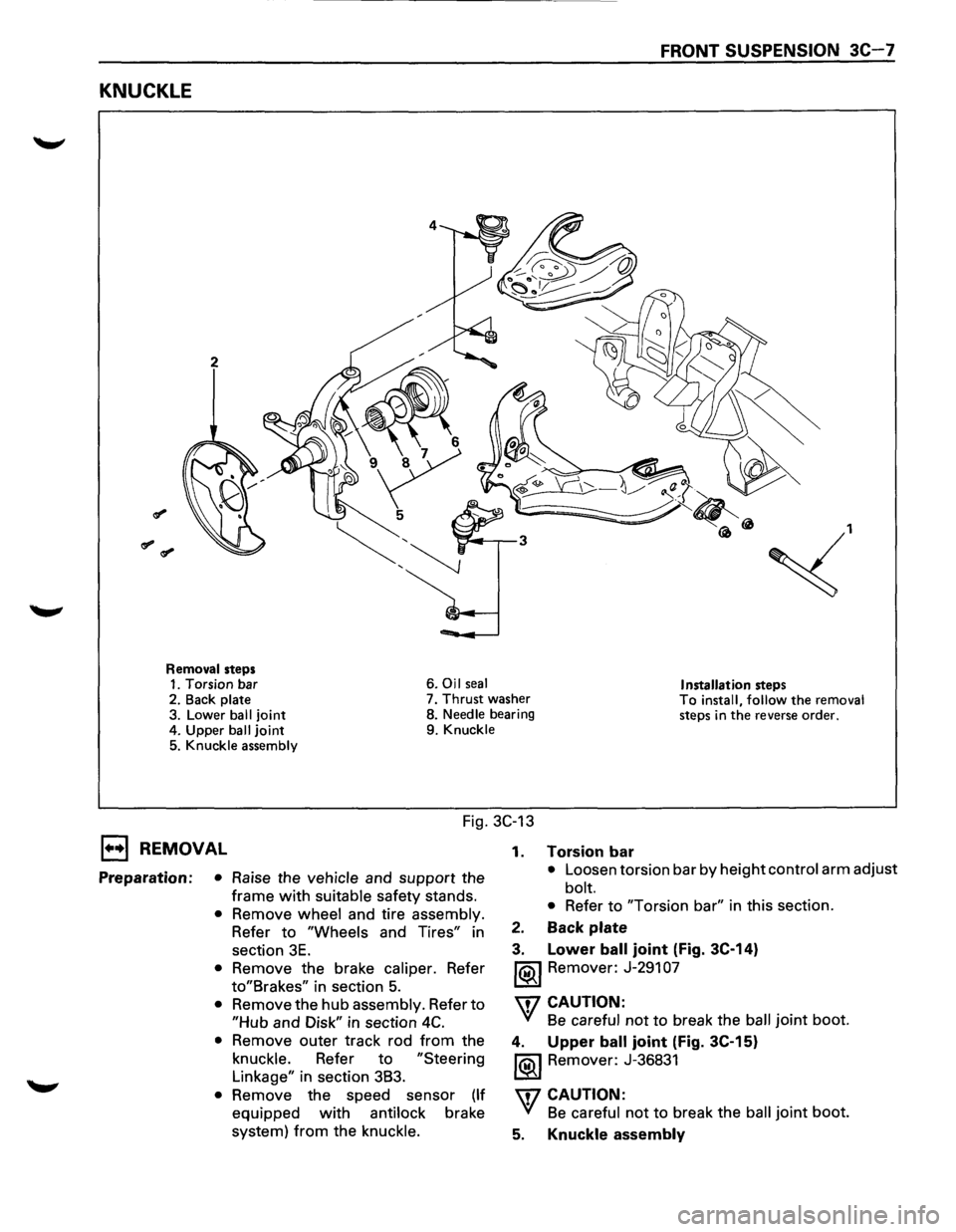
KNUCKLE
2
~,
Removal steps 1. Torsion bar 6. Oil seal Installation steps 2.
Back plate 7. Thrust washer To install, follow the removal steps in the reverse order. 3. Lower ball joint 8. Needle bearing
4. Upper
ball joint 9. Knuckle
5. Knuckle assembly
Fig. 3C-13
1••1 REMOVAL
Preparation: • Raise the vehicle and support the
frame
with suitable safety stands.
• Remove wheel and tire assembly.
Refer to
"Wheels and Tires" in
section
3E.
• Remove the brake caliper. Refer
to"Brakes" in section 5.
• Remove the hub assembly. Refer to
"Hub and Disk" in section 4C.
• Remove outer track rod from the
knuckle. Refer to
"Steering
Linkage" in section 3B3.
• Remove the speed sensor (If
equipped with antilock brake
system)
from the knuckle. 1.
Torsion bar
• Loosen
torsion bar by height control arm adjust
bolt.
• Refer to "Torsion bar" in this section.
2. Back plate
3. Lower ball joint (Fig. 3C-14)
1®.1 Remover: J-291 07
'\f7 CAUTION:
'(! Be careful not to break the ball joint boot.
4. Upper ball joint (Fig. 3C-15)
1®.1 Remover: J-36831
'\f7 CAUTION:
'(! Be careful not to break the ball joint boot.
5. Knuckle assembly
Page 174 of 1928
3C-1 0 FRONT SUSPENSION
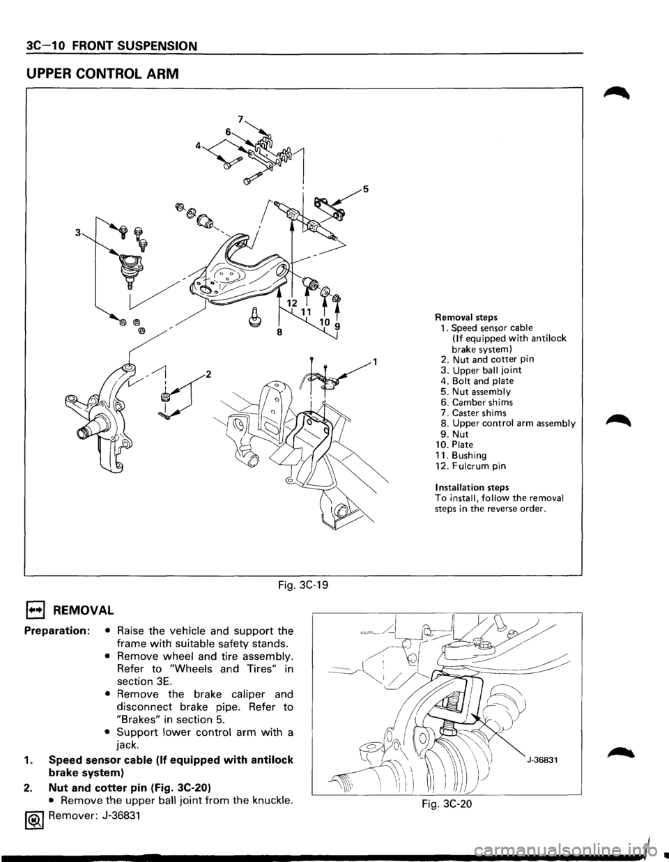
UPPER CONTROL ARM
3
V' , I
Fig. 3C-19
1••1 REMOVAL
Preparation: • Raise the vehicle and support the
frame
with suitable safety stands.
• Remove wheel and tire assembly.
Refer
to "Wheels and Tires" in
section
3E.
• Remove the brake caliper and
disconnect brake pipe. Refer
to
"Brakes" in section 5.
• Support lower control arm with a
jack.
1. Speed sensor cable (If equipped with antilock
brake system)
2.
Nut and cotter pin (Fig. 3C-20)
• Remove the upper ball joint from the knuckle.
1®.1 Remover: J-36831
Removal steps 1. Speed sensor cable
(If equipped with anti lock
brake system)
2. Nut and cotter pin 3. Upper ball joint 4. Bolt and plate 5. Nut assembly 6. Camber shims
7. Caster shims
8.
Upper control arm assembly
9. Nut 10. Plate 11. Bushing
12. Fulcrum pin
Installation steps To install, follow the removal steps in the reverse order.
Fig. 3C-20
Ill
Page 176 of 1928
3C-12 FRONT SUSPENSION
NOTE:
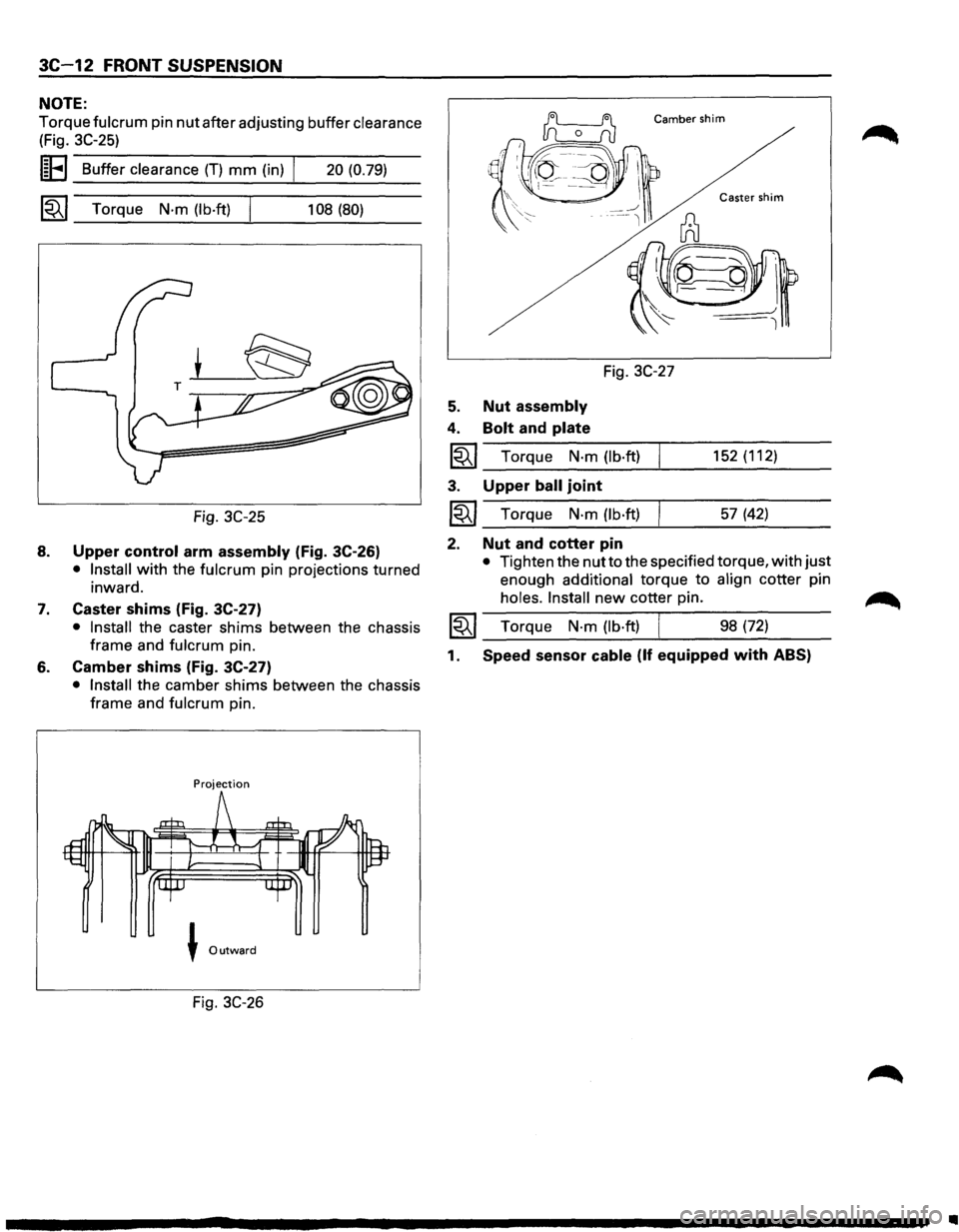
Torque fulcrum pin nut after adjusting buffer clearance
(Fig. 3C-25)
I~EI Buffer clearance (T) mm (in) I 20 (0.79)
~~~ Torque N·m (lb·ft) I 108 (80)
Fig. 3C-25
8. Upper control arm assembly (Fig. 3C-26)
• Install with the fulcrum pin projections turned
inward.
7. Caster shims (Fig. 3C-27)
• Install the caster shims between the chassis
frame and
fulcrum pin.
6. Camber shims (Fig. 3C-27)
• Install the camber shims between the chassis
frame and
fulcrum pin.
Projection
J Outward
Fig. 3C-26
Camber shim
Fig. 3C-27
5. Nut assembly
4. Bolt and plate
1~1 Torque N·m (lb·ft)
3. Upper ball joint
~~~ Torque N·m (lb·ft)
2. Nut and cotter pin
152 (112)
57 (42)
• Tighten the nut to the specified torque, with just
enough
additional torque to align cotter pin
holes. Install new cotter pin.
1~1 Torque N·m (lb·ft) I 98 (72)
1. Speed sensor cable (If equipped with ABS)
•
Page 180 of 1928
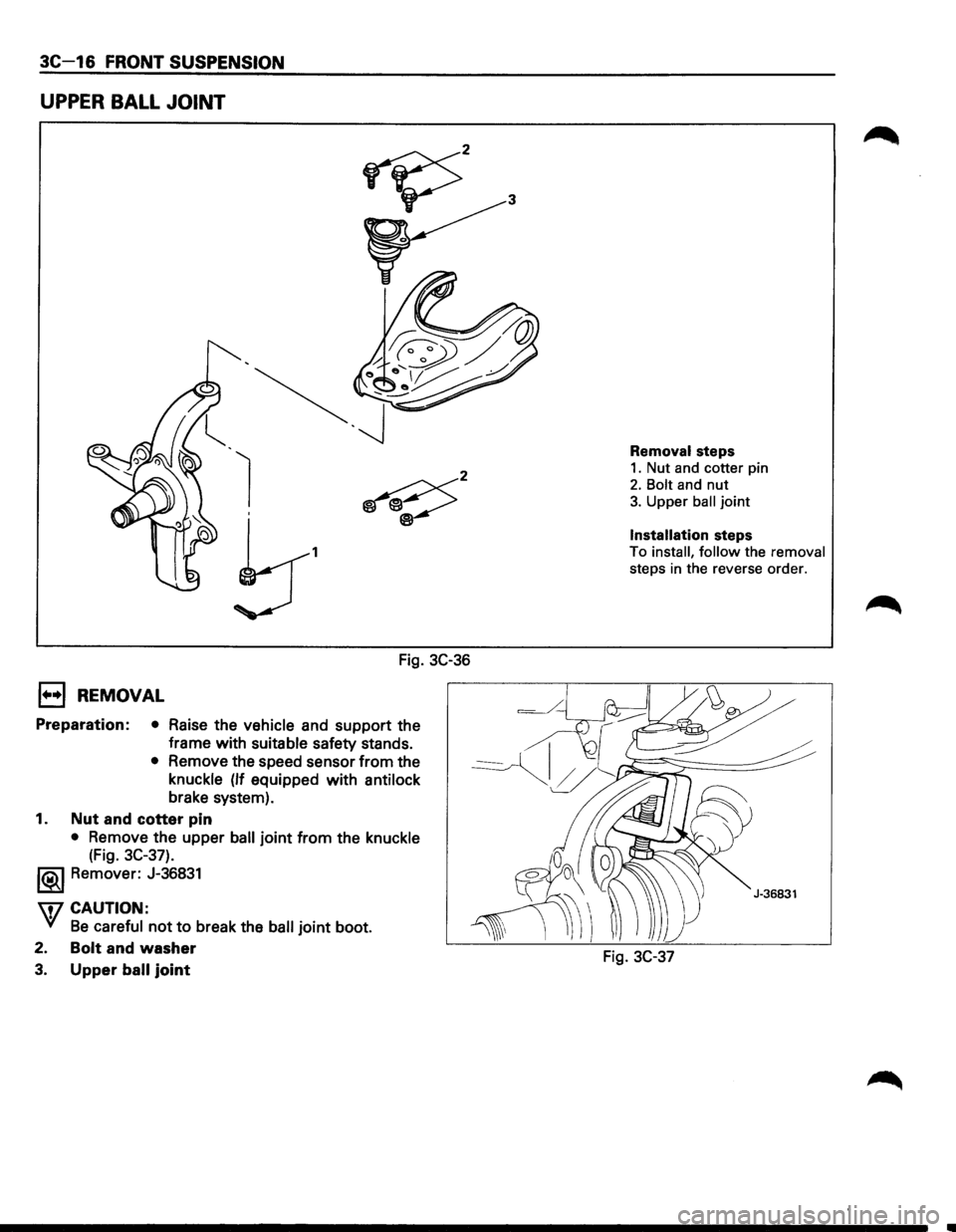
3C-16 FRONT SUSPENSION
UPPER BALL JOINT
1
Fig. 3C-36
E) REMOVAL
Preparation: • Raise the vehicle and support the
frame with
suitable safety stands.
• Remove the speed sensor from the
knuckle
(If equipped with antilock
brake system).
1. Nut and cotter pin
• Remove the upper ball joint from the knuckle
(Fig. 3C-37).
l®..l Remover: J-36831
\fl CAUTION:
VI Be careful not to break the ball joint boot.
2.
Bolt and washer
3. Upper ball joint
Removal steps
1. Nut and cotter pin
2. Bolt and nut
3. Upper ball joint
Installation steps
To install, follow the removal
steps in the reverse order.
Fig. 3C-37
Page 194 of 1928
30-8 REAR SUSPENSION
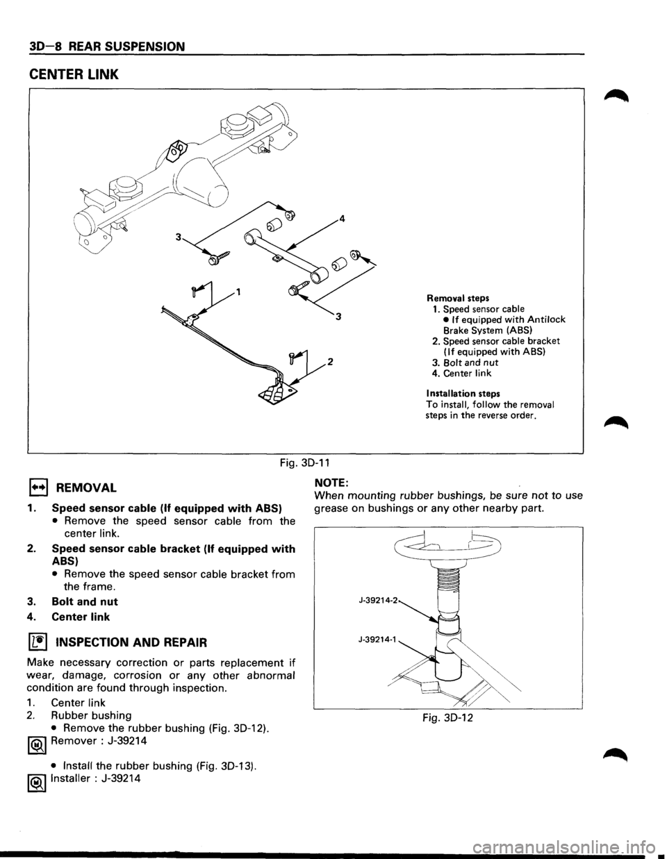
CENTER LINK
2
Removal steps
1. Speed sensor cable
• If equipped with Antilock Brake System (ABS)
2. Speed sensor
cable bracket (If equipped with ABS)
3.
Bolt and nut 4. Center link
Installation
steps
To
install, follow the removal steps in the reverse order.
1•+1 REMOVAL
Fig. 30-11
NOTE:
1.
2.
3.
Speed sensor cable (If equipped with ABS)
• Remove the speed sensor cable from the
center
link.
Speed sensor cable bracket (If equipped with
ABS)
• Remove the speed sensor cable bracket from
the frame.
Bolt and nut
4. Center link
~ INSPECTION AND REPAIR
Make necessary correction or parts replacement if
wear, damage, corrosion or any other abnormal
condition are found through inspection.
1. Center link
2. Rubber bushing
• Remove the rubber bushing (Fig. 30-12).
1®1 Remover : J-39214
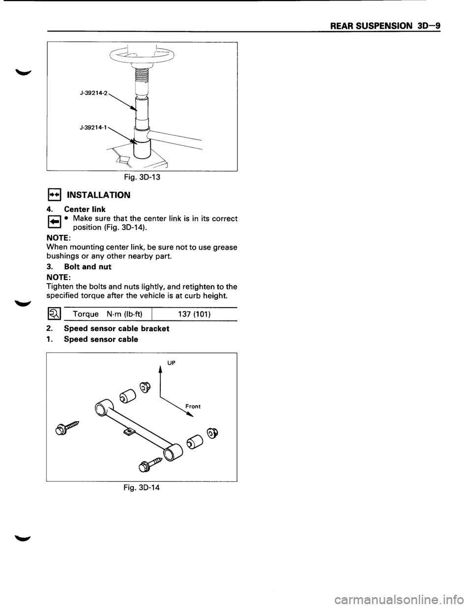
• Install the rubber bushing (Fig. 30-13).
!®..I Installer : J-39214
When mounting rubber bushings, be sure not to use
grease on bushings
or any other nearby part.
J-39214-2
J-39214·1
Fig. 30-12
..
Page 195 of 1928
r-:::::1 )--~
Fig. 30-13
I•+ I INSTALLATION
4. Center link
r=l • Make sure that the center link is in its correct
1.=.1 position (Fig. 30-14).
NOTE:
When mounting center link, be sure not to use grease
bushings
or any other nearby part.
3. Bolt and nut
NOTE:
Tighten the bolts and nuts lightly, and retighten to the
specified torque after the
vehicle is at curb height.
~~~ Torque N·m (lb·ft) /
2. Speed sensor cable bracket
1. Speed sensor cable
UP
Fig. 30-14 137
(101)
REAR SUSPENSION 30-9
Page 244 of 1928
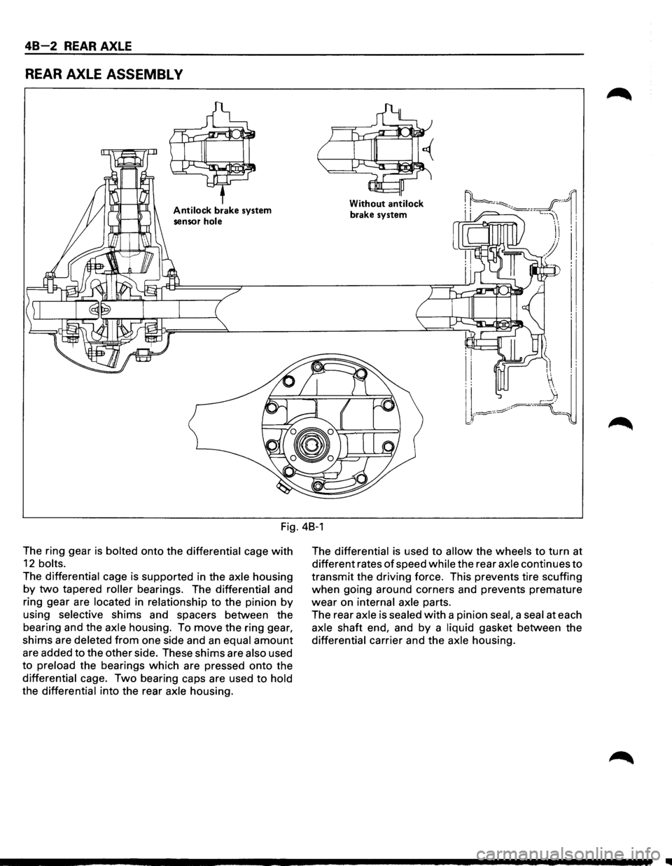
48-2 REAR AXLE
REAR AXLE ASSEMBL V
Antilock brake system
sensor
hole
Without antilock
brake system
Fig. 48-1
The ring gear
is bolted onto the differential cage with
12 bolts.
The differential cage is supported in the axle housing
by two tapered roller bearings. The differential and
ring gear are
located in relationship to the pinion by
using selective shims and spacers between the
bearing and the
axle housing. To move the ring gear,
shims are deleted from one side and an equal amount
are added to the other side. These shims are also used
to preload the bearings which are pressed onto the
differential cage. Two bearing caps are used to hold
the differential into the rear axle housing. The
differential is
used to allow the wheels to turn at
different rates
of speed while the rear axle continues to
transmit the driving force. This prevents tire scuffing
when going around corners and prevents premature
wear on internal axle parts.
The rear
axle is sealed with a pinion seal, a seal at each
axle shaft end, and by a liquid gasket between the
differential carrier and the axle housing.
II
Page 246 of 1928
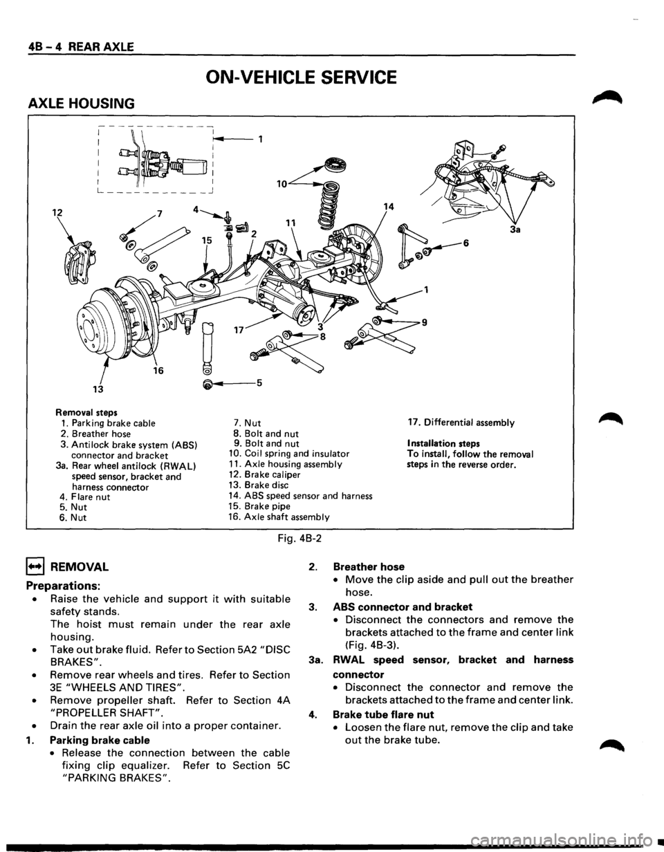
48-4 REAR AXLE
ON-VEHICLE SERVICE
AXLE HOUSING
; ~~:r~4 ,
L ___________ j
12 14
3a
1
• 3
~
~·
13 5
Removal steps
1. Parking brake cable 7. Nut 17.
Differential assembly
2. Breather hose 8.
Bolt and nut 9. Bolt and nut Installation steps
3. Anti lock brake system (ABS)
connector and bracket 10. Coil spring and insulator To install, follow the removal
steps in the reverse order.
3a. Rear wheel antilock (RWAL)
speed sensor, bracket and
harness connector 11.
Axle housing assembly
12. Brake caliper
13. Brake disc
4. Flare
nut 14. ABS speed sensor and harness
5. Nut 15.
Brake pipe
6. Nut 16.
Axle shaft assembly
Fig. 4B-2
1••1 REMOVAL
Preparations:
• Raise the vehicle and support it with suitable
safety stands.
The
hoist must remain under the rear axle
housing.
• Take out brake fluid. Refer to Section 5A2 "DISC
BRAKES".
•
Remove rear wheels and tires. Refer to Section
3E "WHEELS AND TIRES".
•
Remove propeller shaft. Refer to Section 4A
"PROPELLER SHAFT".
•
Drain the rear axle oil into a proper container.
1. Parking brake cable
•
Release the connection between the cable
fixing clip equalizer. Refer to Section 5C
"PARKING BRAKES".
2. Breather hose
• Move the clip aside and pull out the breather
hose.
3. ABS connector and bracket
• Disconnect the connectors and remove the
brackets attached to the frame and center link
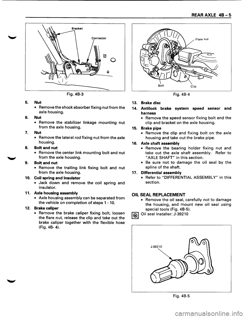
(Fig. 4B-3).
3a. RWAL speed sensor,
bracket and harness
connector
• Disconnect the connector and remove the
brackets attached to the frame and center link.
4. Brake tube flare nut
• Loosen the flare nut, remove the clip and take
out the brake tube.
•
Page 247 of 1928
5.
6.
7.
8.
........,
9.
10.
11.
12.
B 0
g
Fig. 48-3
Nut
• Remove the shock absorber fixing nut from the
axle housing.
Nut
• Remove the stabilizer linkage mounting nut
from the axle housing.
Nut
• Remove the lateral rod fixing nut from the axle
housing.
Bolt and nut
• Remove the center link mounting bolt and nut
from the axle housing .
Bolt and nut
• Remove the trailing link fixing bolt and nut
from the axle housing.
Coil spring and insulator
• Jack down and remove the coil spring and
insulator.
Axle housing assembly
• Axle
housing assembly can be separated from
the vehicle on completion of steps 1 -10.
Brake caliper
•
Remove the brake caliper fixing bolt, loosen
the
flare nut, release the clip and take out the
brake caliper
together with the flexible hose
(Fig. 48-
4).
REAR AXLE 48 - 5
Bolt Clip
Fig. 48-4
13. Brake disc
14.
Antilock brake system speed sensor and
harness
• Remove the speed sensor fixing bolt and the
clip and bracket on the axle housing.
15. Brake
pipe
• Remove the clip and fixing bolt on the axle
housing and take out the brake pipe.
16.
Axle shaft assembly
• Remove the bearing holder fixing nut and
take
out the axle shaft assembly. Refer to
"AXLE SHAFT" in this section.
• Be sure not to damage the oil seal by the
spline of the shaft.
17. Differential
assembly
• Refer to "DIFFERENTIAL ASSEMBLY" in this
section.
OIL SEAL REPLACEMENT
• Remove the oil seal, carefully not to damage
the housing, and mount new oil seal using
special tools (Fig. 48-5).
1®.1 Oil seal installer: J-39210
Fig. 48-5