battery ISUZU TROOPER 1995 Workshop Manual
[x] Cancel search | Manufacturer: ISUZU, Model Year: 1995, Model line: TROOPER, Model: ISUZU TROOPER 1995Pages: 1928
Page 1202 of 1928
8-12 CHASSIS ELECTRICAL
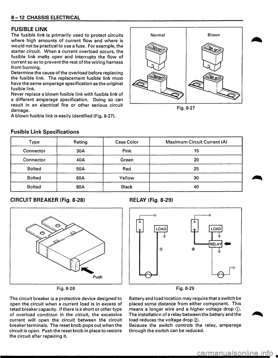
FUSIBLE LINK
The fusible link is primarily used to protect circuits
where high amounts
of current flow and where is
would not be practical to use a fuse. For example, the
starter circuit. When a current
overload occurs, the
fusible link melts open and interrupts the flow of
current so as to prevent the rest of the wiring harness
from burning.
Determine the cause
ofthe overload before replacing
the fusible link. The replacement fusible link must
have the same amperage specification as the original
fusible link.
Never replace a blown fusible link with fusible link of
a different amperage specification. Doing so can
result in an electrical fire or other serious circuit
damage.
A
blown fusible link is easily identified (Fig. 8-27).
Fusible Link Specifications
Normal Blown
Fig.
8-27
Type Rating
Case Color Maximum Circuit Current (A)
Connector
30A Pink 15
Connector 40A Green 20
Bolted 50 A Red 25
Bolted 60A Yellow 30
Bolted
BOA Black 40
CIRCUIT BREAKER (Fig. 8-28)
Push
Fig. 8-28
The circuit breaker is a protective device designed
to
open the circuit when a current load is in excess of
rated breaker capacity. If there is a short or other type
of overload condition in the circuit, the excessive
current
will open the circuit between the circuit
breaker
terminals. The reset knob pops out when the
circuit is open. Push the reset knob in
place to restore
the circuit after repairing it.
RELAY (Fig. 8-29)
Fig. 8-29
Battery and
load location may require that a switch be
placed some distance from either component. This
means a
longer wire and a higher voltage drop G).
The installation of a relay between the battery and the
load reduces the voltage drop®.
Because the switch controls the relay, amperage
through the switch can be reduced.
..
Page 1225 of 1928
::!! cc 00 I U1 N
(
I RR
DOOR
HARNESS
(RH)
I
I DOMEUGHTHARNESSJ
.--------------
I FRT
DOOR
HARNESS
(RH)
I
ENGINE
ROOM
HAR~NESS
~:~i 16
RELAY
& FUSE
BOX
20
(FL-1,
FL-2,
FL-3,
FL-6,
F ) -------------"-
~/ /
BATTERY"------,//
"
\_
(
TAILGATE
HARNESS
(RH)
\,
TAILGATE
HARNESS
(LH)
R-3 R-4
RR
DOOR
HARNESS
ILHl
FRT
DOOR
HARNESS
(LH)
H-22 H-23 H-24
BODY
HARNESS
FUSE
BOX
(C-1
-C-241
ENGINE
ROOM
HARNESS
(
0 :1: )> fJ)
fJ) Ci) m rm 0 -4 ::0 n )> r-eo I w (J1
Page 1228 of 1928
8-38 CHASSIS ELECTRICAL
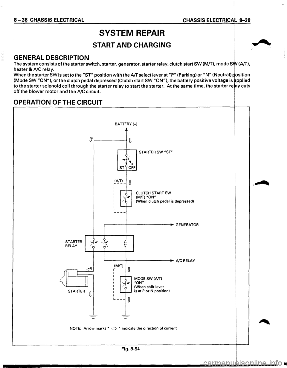
GENERAL DESCRIPTION
SYSTEM REPAIR
START AND CHARGING
CHASSIS ELECTRIC L 8-38
The system consists ofthe starter switch, starter, generator, starter relay, clutch start SW (M/T), mode SW (A/T),
heater & AJC relay.
When the starter SW is set to the "ST" position with the AJT select lever at "P" (Parking) or "N" (Neutral)~ osition
(Mode SW "ON"), or the clutch pedal depressed (Clutch start SW "ON"), the battery positive voltage is ~pplied
to the starter solenoid coil through the starter relay to start the starter. At the same time, the starter re ay cuts
off the blower motor and the AJC circuit.
OPERATION OF THE CIRCUIT
STARTER RELAY
<~
STARTER
BATTERY(+)
~ .. ~ ~ ST OFF
~A!fJ-D I I -r-1 I I I I I
STARTER SW ·sTn
CLUTCH START SW (MfTl ·ow (When clutch pedal is depressed)
,-------+----------.GENERATOR
~ ';
L.-----+----------. A/C RELAY
¢!) (MrrJ
D r---I
I
I r--r-MODE SW (A/T) I ~ I y, ·oNn I /~ (When shift lever I is at P or N position)
D I -r-I L ___
D
NOTE: Arrow marks • c:::::> • indicate the direction of current
Fig. 8-54
•
Page 1229 of 1928
, cCi" 00 I (11
(11
(
CLUTCH
START
SW
(M/Tl
ANTI-THEFT
CONTROLLER
STARTER
RELAY:
STARTER
" ~-
X-17
P-2
-, '
RELAY
& FUSE
BOX
(FL-1,
FL-2)
""" "'
P-1
'
----------
... / ,.,
BATTERY
If
I
GROUND: BODY
/ H-41
,_
(
STARTERSW
( RELAY:
HEATER
&AIC
FUSE
BOX
(C-1,C-8,C-19,C-20)
CLUTCH
PEDAL
(M{T)
MODE
SW.
(A/11
(
~ ::lJ -1 CJ) r-0 (") ~ 0 2
n ::1: ~ (I) en m rm ~ n )> r-eo I (A) CD
Page 1234 of 1928
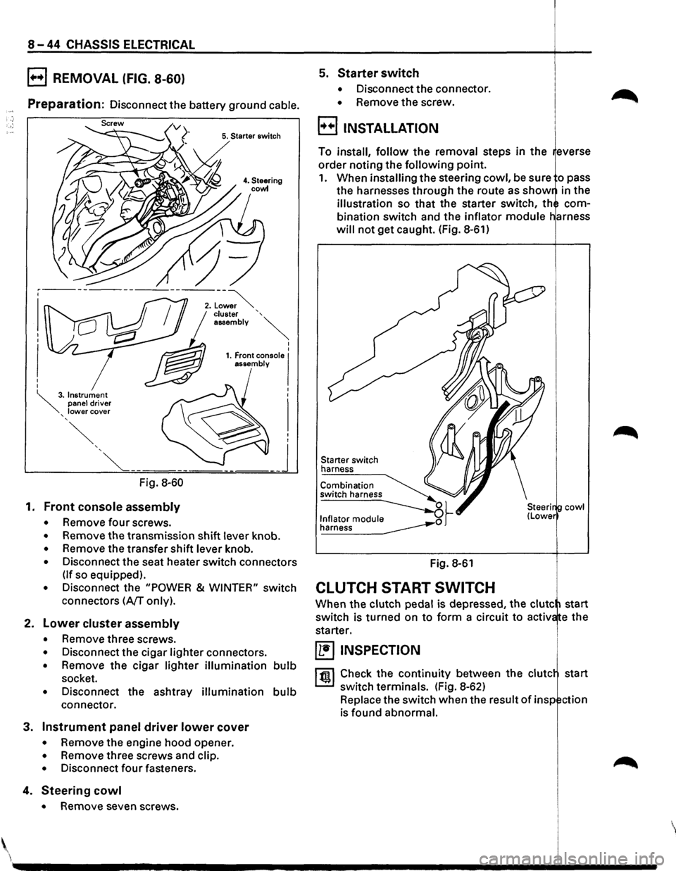
8-44 CHASSIS ELECTRICAL
B REMOVAL (FIG. 8-60)
Preparation: Disconnect the battery ground cable.
5. Starter switch
Fig. 8-60
1. Front console assembly
• Remove four screws.
• Remove the transmission shift lever knob.
• Remove the transfer shift lever knob.
• Disconnect the seat heater switch connectors
(If so equipped).
• Disconnect the "POWER & WINTER" switch
connectors
(A/T only).
2. Lower cluster assembly
• Remove three screws.
• Disconnect the cigar lighter connectors.
• Remove the cigar lighter illumination bulb
socket.
• Disconnect the ashtray illumination bulb
connector.
3. Instrument panel driver lower cover
• Remove the engine hood opener.
• Remove three screws and clip.
• Disconnect four fasteners.
4. Steering cowl
• Remove seven screws .
5. Starter switch
• Disconnect the connector.
• Remove the screw.
B INSTALLATION
To install, follow the removal steps in the everse
order noting the
following point.
1. When installing the steering cowl, be sure o pass
the harnesses through the route as
show in the
illustration so that the starter switch, th com
bination switch and the inflator
module
will not get caught. (Fig. 8-61)
Starter switch
harness
Fig. 8-61
CLUTCH START SWITCH
cowl
When the clutch pedal is depressed, the clute start
switch is turned on
to form a circuit to activ e the
starter.
~ INSPECTION
1 til!. I Check the continuity between the clute start
switch terminals. (Fig. 8-62)
Replace the switch when the result
of insp ction
is found abnormal.
'
Page 1235 of 1928
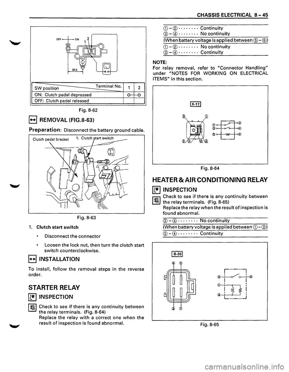
OFF
SW position Terminal No.
ON: Clutch pedal depressed
OFF: Clutch pedal released
Fig. 8-62
B REMOVAL (FIG.S-63)
2
Preparation: Disconnect the battery ground cable.
Fig. 8-63
1. Clutch start switch
Disconnect the connector
Loosen the lock nut, then turn the clutch start
switch counterclockwise.
B INSTALLATION
To install, follow the removal steps in the reverse
order.
STARTER RELAY
~ INSPECTION
ltgl Check to see if there is any continuity between
the relay terminals. (Fig. 8-64)
Replace the relay with a correct one when the
result of inspection is found abnormal.
CHASSIS ELECTRICAL 8-45
CD-®······ · · Continuity
@-G)· . · · · · .. No continuity
(When battery voltage is applied between®-@)
CD-®· · · · · · · · No continuity
@-G)· · · · · · · · Continuity
NOTE:
For relay removal, refer to "Connector Handling"
under "NOTES FOR WORKING ON ELECTRICAL
ITEMS"
in this section.
®JI
@~
®
Fig. 8-64
HEATER & AIR CONDITIONING RELAY
~ INSPECTION
l'fll Check to see if there is any continuity between
~ the relay terminals. (Fig. 8-65)
Replace the relay when the result of inspection is
found abnormal.
®-G) ..... · .. No continuity
(When battery voltage is applied between CD-@)
®-G) .... · · .. Continuity
Fig. 8-65
Page 1246 of 1928
8-56 CHASSIS ElECTRICAl
STARTER SWITCH NOTE:
Refer
to START AND CHARGING in this section. For relay
removal, refer to "Connector H ndling" ~
under "NOTES FOR WORKING ON ELE TRICAL .,..........
DATA LINK CONNECTOR ITEMS" in this section.
The data
link connector (white) is used to retrieve the
diagnostic
trouble codes stored from the engine UPSHIFT-1 RELAY
control module. The data link connector is installed at .----------------+----.
inside of the instrument panel driver lower cover.
(Fig. 8-72)
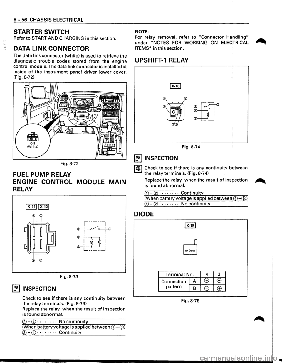
Fig. 8-72
FUEL PUMP RELAY
ENGINE CONTROL MODULE MAIN
RELAY
,-------,
"" __!.___./, ' 4 '<)I ~
Fig. 8-73
~ INSPECTION
Check to see if there is any continuity between
the
relay terminals. (Fig. 8-73)
Replace the relay when the result of inspection
is found
abnormal.
®-@ · · · · · · · · No continuity
(When battery voltage is applied between CD-@)
®-@ · · · · · · · · Continuity
m
Fig. 8-74
~ INSPECTION
ltgl Check to see if there is any continuity b tween
the
relay terminals. (Fig. 8-7 4)
Replace the relay when the result of ins ~
is found abnormal.
DIODE
Terminal No. 4 3
Connection A (±) 8
pattern 8 8 (±)
Fig.
8-75
..
Page 1247 of 1928
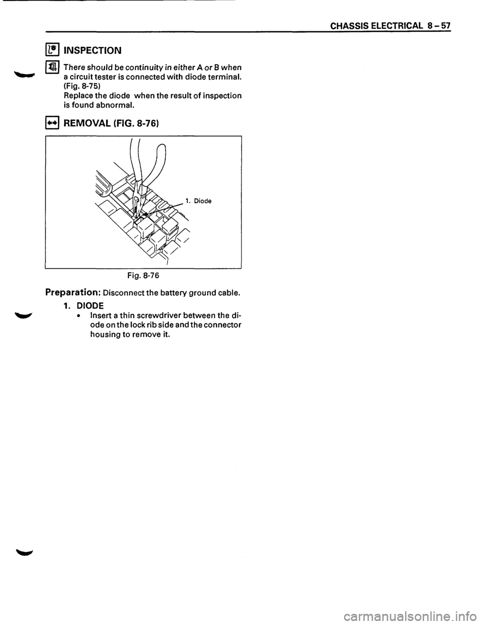
~ INSPECTION
I~ I There should be continuity in either A or 8 when
a circuit tester is connected with diode terminal.
(Fig. 8-75)
Replace the diode when the result of inspection
is found abnormal.
B REMOVAL (FIG. 8-76)
Fig. 8-76
Preparation: Disconnect the battery ground cable.
1. DIODE
• Insert a thin screwdriver between the di
ode on
the lock rib side and the connector
housing to remove it.
CHASSIS ELECTRICAL 8-57
Page 1248 of 1928
8-58 CHASSIS ELECTRICAL
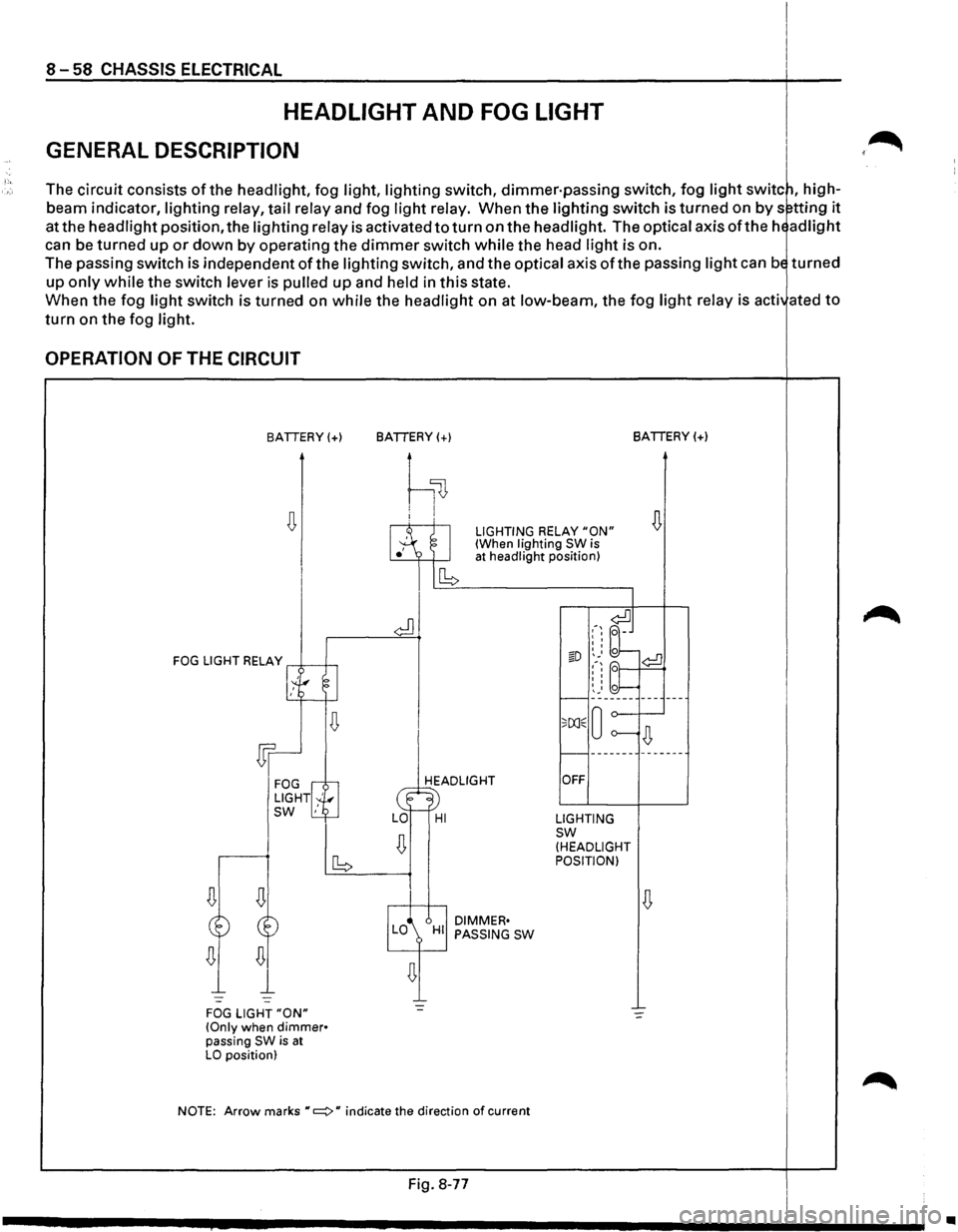
HEADLIGHT AND FOG LIGHT
GENERAL DESCRIPTION
The circuit consists of the headlight, fog light, lighting switch, dimmer·passing switch, fog light switc~, high
beam indicator,
lighting relay, tail relay and fog light relay. When the lighting switch is turned on by s~tting it
at the headlight position, the lighting relay is activated to turn on the headlight. The optical axis oft he hE ad light
can be turned up or down by operating the dimmer switch while the head light is on.
The passing switch is independent
of the lighting switch, and the optical axis ofthe passing light can bE turned
up only while the switch lever is pulled up and held in this state.
When the fog
light switch is turned on while the headlight on at low-beam, the fog light relay is acti ated to
turn on the fog light.
OPERATION OF THE CIRCUIT
BATTERY(+)
FOG LIGHT RELAY .--*-----1--,
1.~---g I
~
Wr
FOG rG LIGHT! '!r_., SW ,
FOG LIGHT "ON" (Only when dimmer• passing SW is at LO position) BATTERY(+)
BATTERY(+)
h~
I.A ~I
LIGHTING RELAY "ON" (When lighting SW is
ICb
at
headlight position)
HEADLIGHT
~· LO-HI
I
DIMMER• LO HI PASSING SW
I
.-~ ~J I I
I I
§D ~_. o ¢:!]
~-~ bt I I I I
I I 0 r--~: _____ ------
o;[X]E 0 o----~
r----------------
OFF
LIGHTING sw (HEADLIGHT
POSITION)
NOTE:
Arrow marks "c::::::>" indicate the direction of current
Fig. 8-77
J •
Page 1253 of 1928
![ISUZU TROOPER 1995 Workshop Manual CHASSIS ELECTRICAL 8-63
1-1. BOTH HEADLIGHTS INOPERATIVE
• IS THE LIGHTING RELAY NORMAL? I
I
I I
YES I NO I
I
I
• IS [[I[] GROUNDED SECURELY? I REPLACE THE LIGHTING RELAY I
I
I
I
YES](/img/61/57183/w960_57183-1252.png "ISUZU TROOPER 1995 Workshop Manual CHASSIS ELECTRICAL 8-63
1-1. BOTH HEADLIGHTS INOPERATIVE
• IS THE LIGHTING RELAY NORMAL? I
I
I I
YES I NO I
I
I
• IS [[I[] GROUNDED SECURELY? I REPLACE THE LIGHTING RELAY I
I
I
I
YES")
CHASSIS ELECTRICAL 8-63
1-1. BOTH HEADLIGHTS INOPERATIVE
• IS THE LIGHTING RELAY NORMAL? I
I
I I
YES I NO I
I
I
• IS [[I[] GROUNDED SECURELY? I REPLACE THE LIGHTING RELAY I
I
I
I
YES I NO I
I I
• IS THE DIODE NORMAL? J GROUND IT SECURELY I
I
I I
YES I NO I
I
I
• DISCONNECT THE LIGHTING SW CONNECTOR REPLACE THE DIODE J • IS THE BATTERY VOLTAGE APPLIED BETWEEN THE HARNESS
SIDE CONNECTOR 1 [[I[j AND GROUND?
I
I I
YES I NO I
I I
• REMOVE THE LIGHTING SW REPAIR A POOR CONNECTION AT THE CONNECTORS
• IS THERE CONTINUITY BETWEEN 1 [[I[] AND 7 ~WHEN OR AN OPEN CIRCUIT BETWEEN THE FUSUBLE LINK SETTING THE LIGHTING SWAT THE HEADLIGHT POSITION? FL-1 (80A) AND 1 ~
I
I I
I YES I NO I
1 I
REPAIR A POOR CONNECTION AT THE CONNECTORS OR AN REPAIR OR REPLACE THE LIGHTING SW I OPEN CIRCUIT BETWEEN THE HARNESS SIDE CONNECTOR 1WI] AND~ (GROUND) OF THE LIGHTING SW