battery ISUZU TROOPER 1995 Workshop Manual
[x] Cancel search | Manufacturer: ISUZU, Model Year: 1995, Model line: TROOPER, Model: ISUZU TROOPER 1995Pages: 1928
Page 1041 of 1928
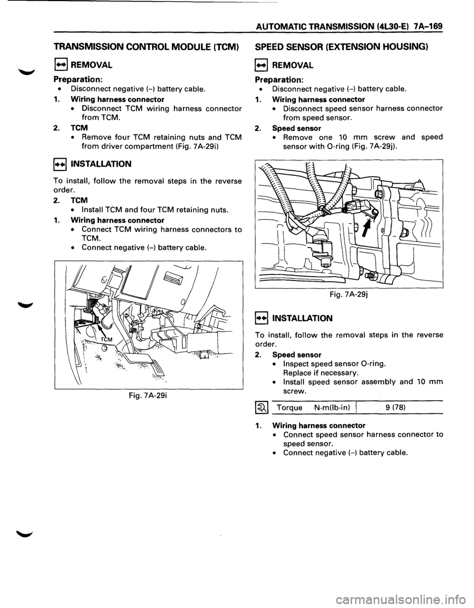
TRANSMISSION CONTROL MODULE (TCM)
1+•1 REMOVAL
Preparation:
• Disconnect negative (-) battery cable.
1. Wiring harness connector
• Disconnect TCM wiring harness connector
from TCM.
2. TCM
• Remove four TCM retaining nuts and TCM
from driver compartment (Fig. 7A-29i)
!•+I INSTALLATION
To install, follow the removal steps in the reverse
order.
2. TCM
• Install TCM and four TCM retaining nuts.
1. Wiring harness connector
• Connect TCM wiring harness connectors to
TCM.
• Connect negative (-) battery cable.
Fig. 7A-29i
AUTOMATIC TRANSMISSION (4L30-El 7A-169
SPEED SENSOR (EXTENSION HOUSING)
1+•1 REMOVAL
Preparation:
• Disconnect negative (-) battery cable.
1. Wiring harness connector
• Disconnect speed sensor harness connector
from speed sensor.
2. Speed sensor
• Remove one 10 mm screw and speed
sensor
with 0-ring (Fig. 7 A-29j).
Fig. 7A-29j
I•+IINSTALLATION
To install, follow the removal steps in the reverse
order.
2. Speed sensor
• Inspect speed sensor 0-ring.
Replace if necessary.
• Install speed sensor assembly and 10 mm
screw.
~~~ Torque N·mOb·in) 9 (78)
1. Wiring harness connector
• Connect speed sensor harness connector to
speed sensor.
• Connect negative (-) battery cable.
Page 1042 of 1928
7 A-170 AUTOMATIC TRANSMISSION (4L30-E)
TRANSMISSION OIL TEMPERATURE
SENSOR (ADAPTER CASE)
1•+1 REMOVAL
Preparation:
• Disconnect negative (-) battery cable.
•
Remove exhaust protector and exhaust pipe.
• Drain fluid.
•
Refer to "CHANGING TRANSMISSION FLUID".
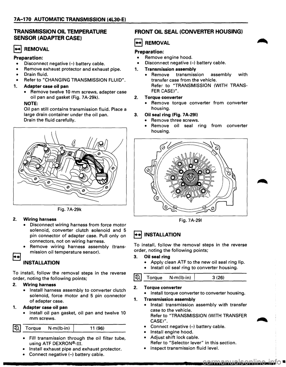
1. Adapter case oil pan
• Remove twelve 10 mm screws, adapter case
oil pan and gasket (Fig. 7 A-29k).
NOTE:
Oil
pan still contains transmission fluid. Place a
large drain container under the oil pan.
Drain the
fluid carefully.
Fig. 7A-29k
2. Wiring harness
• Disconnect wiring harness from force motor
solenoid, converter clutch solenoid and 5
pin connector
of adapter case. Pull only on
connectors,
not on wiring harness.
• Remove wiring harness assembly (trans
B mission oil temperature sensor).
INSTALLATION
To install, follow the removal steps in the reverse
order, noting the
following points;
2.
Wiring harness
• Install harness assembly to converter clutch
solenoid,
force motor and 5 pin connector
of adapter case.
1. Adapter case oil pan
• Install oil pan gasket, oil pan and twelve 10
mm screws.
~~~ Torque N·mOb·in) I 11 (96)
• Fill transmission through the oil filter tube,
using ATF
DEXRON®-111.
• Install exhaust pipe and exhaust protector.
• Connect negative (-) battery cable.
FRONT OIL SEAL (CONVERTER HOUSING)
l++l REMOVAL
Preparation:
• Removt~ engine hood.
• Disconnect negative (-) battery cable.
1. Transmission assembly
•
Remove transmission assembly with
transfer case from the vehicle.
Refer to "TRANSMISSION (WITH TRANS
FER CASE)".
2. Torque converter
• Remove torque converter from converter
housing.
3.
Oil seal ring (Fig. 7 A-291)
• Remove three screws.
• Remove oil seal ring from converter
housing.
Fig.
7A-291
I++IINSTALLATION
To install, follow the removal steps in the reverse
order, noting the
following points;
3. Oil seal ring
• Apply clean ATF to the new oil seal ring lip.
• Install oil seal
ring to converter housing.
~~~ Torque N·mOb·in) I 3 (26)
2. Torque converter
• Install torque converter to converter housing.
1. Transmission assembly
• Install
transmission assembly with transfer
case
to the vehicle.
Refer to "TRANSMISSION (WITH TRANSFER
CASE I".
• Connoct negative (-) battery cable.
• Install
engine hood.
• Adjust shift lock cable.
Refer to "Selector lever" in this section.
• Inspect transmission fluid level.
•
Page 1043 of 1928
REAR OIL SEAL (EXTENSION HOUSING)
l••l REMOVAL
Preparation:
• Disconnect negative (-) battery cable.
1. Transfer case assembly
• Remove transfer case assembly from the
vehicle.
Refer to "SECTION 70 TRANSFER CASE
(AfT')".
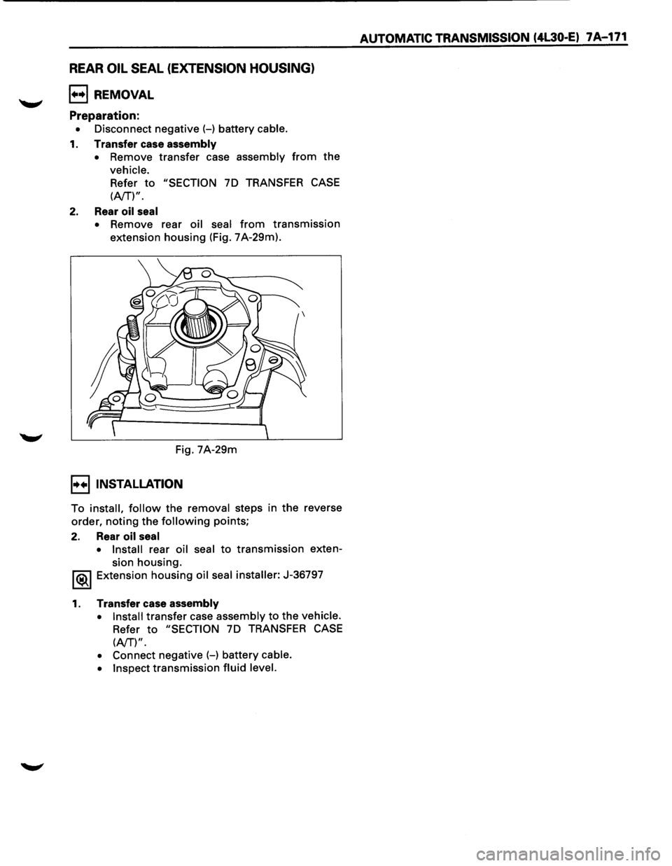
2. Rear oil seal
• Remove rear oil seal from transmission
extension housing (Fig. 7A-29m).
Fig. 7A-29m
I••IINSTALLATION
To install, follow the removal steps in the reverse
order,
noting the following points;
2. Rear oil seal
• Install rear oil seal to transmission exten
sion housing.
1®..1 Extension housing oil seal installer: J-36797
1. Transfer case assembly
• Install transfer case assembly to the vehicle.
Refer to "SECTION 70 TRANSFER CASE
(AfT')".
• Connect negative (-) battery cable.
• Inspect
transmission fluid level.
AUTOMATIC TRANSMISSION (4L30·E) 7A-171
Page 1084 of 1928
7A-212 AUTOMATIC TRANSMISSION (4L30-E)
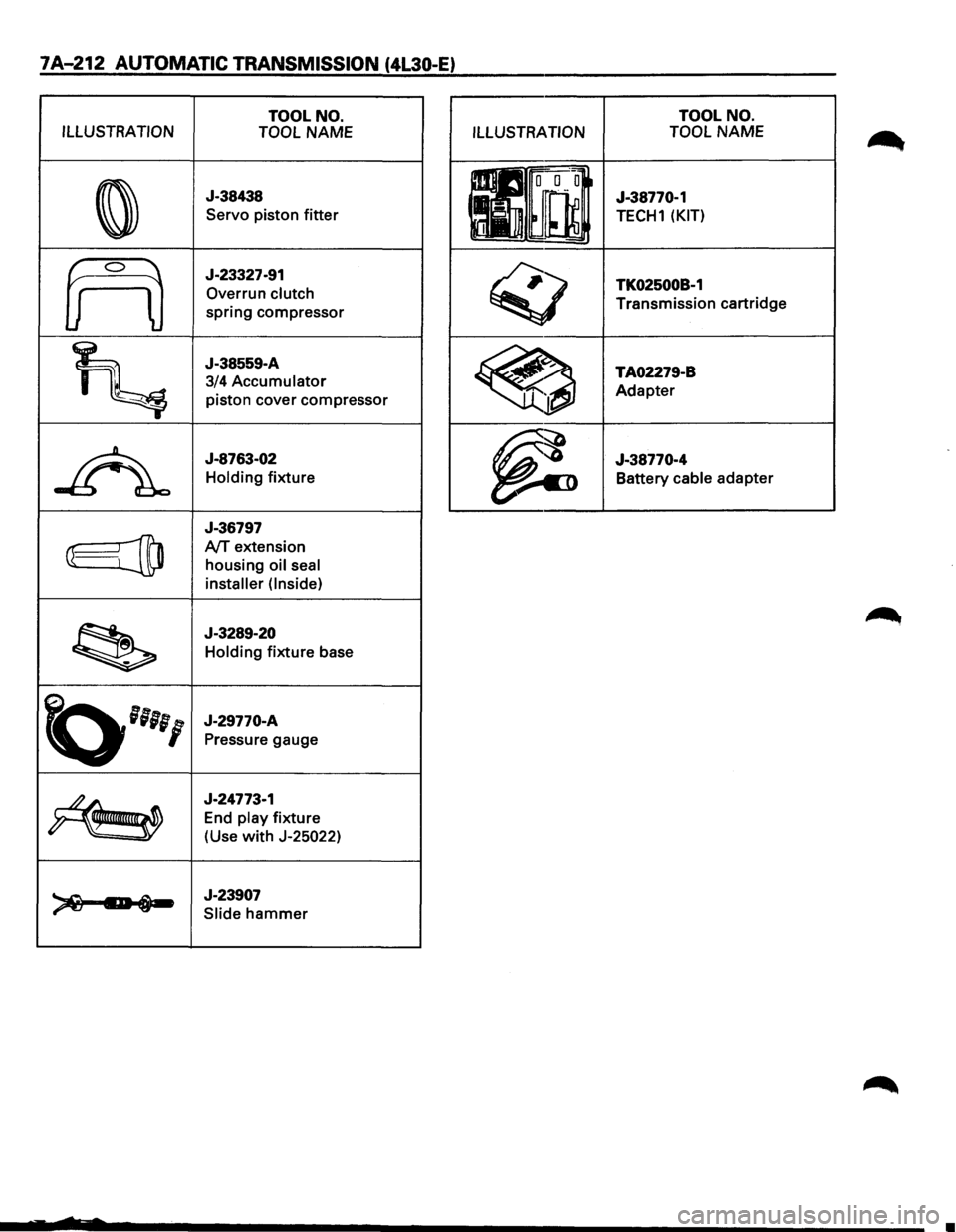
TOOL NO.
ILLUSTRATION TOOL
NAME
0
J-38438
Servo piston
fitter
frO
J-23327-91
Overrun
clutch
spring compressor
~
J-38559-A
3/4
Accumulator
piston cover compressor
~
J-8763-02
Holding fixture
J-36797
@jtD A/T extension
housing
oil seal
installer (Inside)
~
J-3289-20
Holding fixture base
~''''I
J-29770-A
Pressure gauge
~
J-24773-1
End
play fixture
(Use
with J-25022)
~ 1:-i-J-23907
Slide hammer
ILLUSTRATION TOOL
NO.
TOOL NAME
J-38770-1
TECH1 (KIT)
TK02500B-1
Transmission cartridge
TA02279-B Adapter
J-38770-4 Battery
cable adapter
•
Page 1095 of 1928
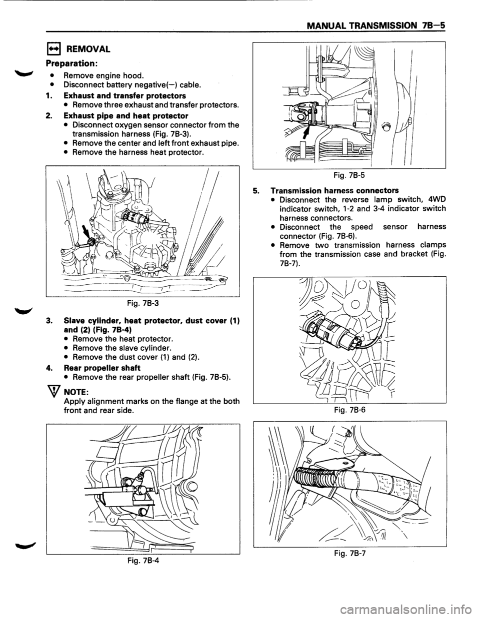
EJ REMOVAL
Preparation:
'--"' • Remove engine hood.
• Disconnect battery negative(-) cable.
1. Exhaust and transfer protectors
• Remove three exhaust and transfer protectors.
2. Exhaust pipe and heat protector
3.
• Disconnect oxygen sensor connector from the
transmission harness (Fig. 78-3).
• Remove the center and left front exhaust pipe.
• Remove the harness heat protector.
lj
Fig. 78-3
Slave cylinder, heat protector, dust cover (1)
and (2) (Fig. 78-4)
• Remove the heat protector.
• Remove the slave cylinder.
•
Remove the dust cover (1) and (2).
4. Rear propeller shaft
• Remove the rear propeller shaft (Fig. 78-5).
W NOTE:
Apply alignment marks on the flange at the both
front and rear side.
Fig. 78-4
MANUAL TRANSMISSION 78-5
Fig. 78-5
5. Transmission harness connectors
• Disconnect the reverse lamp switch, 4WD
indicator switch,
1-2 and 3-4 indicator switch
harness connectors.
• Disconnect the speed sensor harness
connector (Fig. 78-6).
• Remove two transmission harness clamps
from the transmission case and bracket (Fig.
78-7).
Fig. 78-6
Fig. 78-7
Page 1099 of 1928
12. Flywheel under cover bolts
• Install
three flywheel under cover bolts.
11. Gear control lever
• Install
the transmission control lever and
transfer
control lever.
• Install
the grommet assembly.
• Install
the front console assembly.
• Install
the gear control lever knob.
• Support the transfer case with a jack and then
remove the transmission jack
from
transmission side.
10. Front propeller shaft
• Install the front propeller shaft.
~~~ Torque N·m (lb·ft) 63 (46)
9. Front crossmember
• Install the front crossmember.
~~~ Torque N·m (lb·ft) 78 (58)
8. Engine rear mount
• Install the engine rear mount.
~~~ Torque N·m (lb·ft) 41 (30)
7. 3rd crossmember
• Install the 3rd crossmember.
1~1 Torque N-m (lb·ft) 50 (37)
6. Engine rear mount nuts
~~~ Torque N-m (lb·ft) 50 (37)
• Remove the transmission jack.
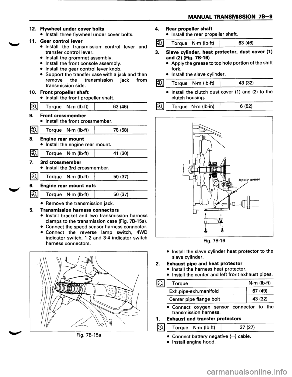
5. Transmission harness connectors
• Install bracket and two transmission harness
clamps to the transmission case (Fig. 78-15a).
• Connect the speed sensor harness connector.
• Connect the reverse lamp switch, 4WD
indicator
switch, 1-2 and 3-4 indicator switch
harness connectors.
Fig. 78-15a
MANUAL TRANSMISSION 78-9
4. Rear propeller shaft
• Install the rear propeller shaft.
I~I __ T_o_rq~u_e __ N_·m~(_lb_·ft~)~ _____ 6_3~(_46~) ____ _
3. Slave cylinder. heat protector. dust cover (1)
and (2) (Fig. 78-16)
• Apply the grease to top hole portion of the shift
fork.
• Install the slave cylinder.
~~~ Torque N·m (lb·ft) I 43 (32) _..:....__~----
• Install the clutch dust cover (1) and (2) to the
clutch housing.
~~~ Torque N·m (lb·in) 6 (52)
Apply grease
Fig. 78-16
• Install the slave cylinder heat protector to the
slave cylinder.
2. Exhaust pipe and heat protector
• Install the harness heat protector.
• Install the center and left front exhaust pipes.
~~~ Torque
Exh.pipe-exh.manifold
Center pipe
flange bolt N·m
(lb·ft)
67 (49)
43 (32)
• Connect oxygen sensor connector to the
transmission harness.
1. Exhaust and transfer protectors
~~~ Torque N·m (lb·ft) 37 (27)
• Connect battery negative (-) cable.
• Install
engine hood.
Page 1100 of 1928
78-10 MANUAL TRANSMISSION
GEAR CONTROL BOX ASSEMBLY
l••l REMOVAL
Preparation:
• Disconnect battery negative (-) cable.
1. Knob
• Remove knobs of the transmission control
lever
and transfer control lever.
2. Front console assembly
• Remove front console assembly.
•
Disconnect harness connector.
• Remove rear heater duct.
3. Grommet assembly
• Remove grommet assembly.
4. Transmission control lever and transfer control
lever
• Remove transmission control lever and
transfer
control lever.
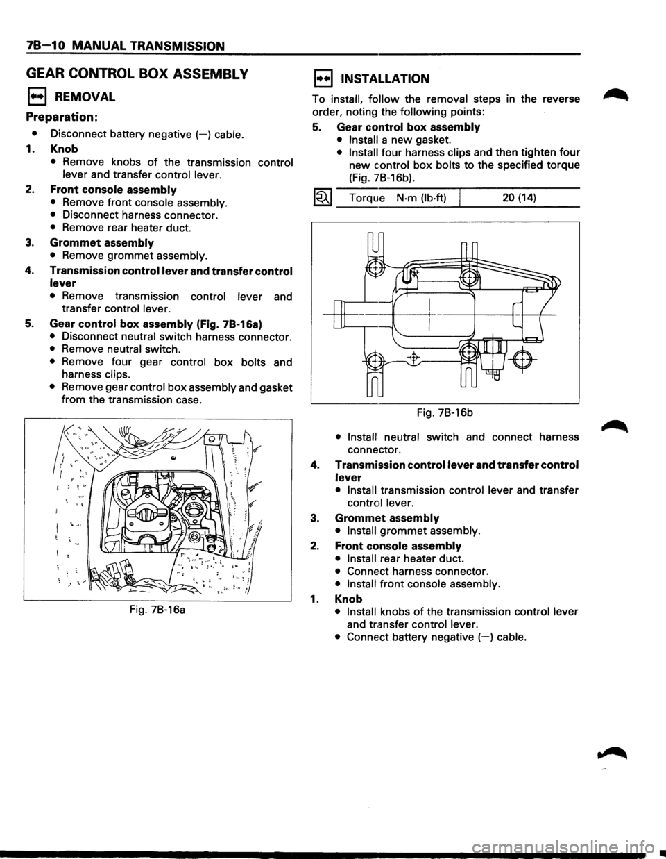
5. Gear control box assembly (Fig. 7B-16a)
• Disconnect neutral switch harness connector.
• Remove neutral switch.
• Remove four gear control box bolts and
harness
clips.
•
Remove gear control box assembly and gasket
from the transmission case.
Fig. 7B-16a
l••l INSTALLATION
To install, follow the removal steps in the reverse
order, noting the
following points:
5. Gear control box assembly
• Install a new gasket.
• Install four harness clips and then tighten four
new control box bolts to the specified torque
(Fig. 7B-16b).
1~1 Torque N·m (lb·ft) 20 (14)
Fig. 7B-16b
• Install neutral switch and connect harness
connector.
4.
Transmission control lever and transfer control
lever
• Install transmission control lever and transfer
control lever.
3. Grommet assembly
• Install grommet assembly.
2. Front console assembly
• Install rear heater duct.
• Conne,ct harness connector.
• Install front console assembly.
1. Knob
• Install knobs of the transmission control lever
and transfer control lever.
• Conne·ct
battery negative (-) cable.
•
Page 1161 of 1928
TRANSFER CASE 70-3
ON-VEHICLE SERVICE
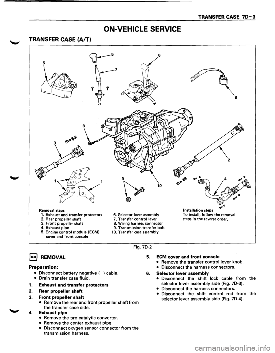
TRANSFER CASE (A/T)
5
<;J---5 6
7
' 8
9
~
10
Removal steps Installation steps
1. Exhaust and transfer protectors 6. Selector lever
assembly To
install, follow the removal
steps in the reverse order.
2. Rear propeller shaft 7.
Transfer control lever
3. Front propeller shaft 8.
Wiring harness connector
4. Exhaust pipe 9. Transmission-transfer bolt
5. Engine control module
(ECM)
cover and front console 10.
Transfer case assembly
Fig. 7D-2
l••l REMOVAL
Preparation:
• Disconnect battery negative (-) cable.
•
Drain transfer case fluid.
1. Exhaust and transfer protectors
2. Rear propeller shaft
3. Front propeller shaft
• Remove the rear and front propeller shaft from
the transfer case side.
4. Exhaust pipe
• Remove the pre-catalytic converter.
• Remove the center exhaust pipe.
• Disconnect oxygen sensor connector from the
transmission harness.
5. ECM cover and front console
• Remove the transfer control lever knob.
• Disconnect the harness connectors.
6. Selector lever assembly
• Disconnect the shift lock cable from the
selector lever assembly side (Fig. 7D-3).
• Disconnect the harness connectors.
• Disconnect the shift control rod from the
selector lever assembly side (Fig. 7D-4).
Page 1192 of 1928
-·*; ~---
8-2 CHASSIS ELECTRICAL
GENERAL INFORMATION
The chassis electrical system is of 12-volt specifications with a negative ground polarity.
Wire sizes are appropriate
to respective circuits, and classified by color. (The classification of harnesses by
color is shown on the circuit diagram for ease of harness identification.)
The
wire size is determined by load capacity and the length of wire required.
The
vehicle harnesses are: body harness, chassis harness, engine room harness, instrument harness,
transmission harness, engine
ECGI harness, dome light harness, door harness, rear body harness, tailgate
harness,
SRS harness and battery cables.
The harnesses are protected either
by tape or corrugated tube, depending on harness location.
The circuit
for each system consists of the power source, wire, fuse, relay, switch, load parts and ground, all of
which are shown on the circuit diagram.
In this manual, each electrical device is classified by system. For major parts shown on the circuit based on
the circuit diagram
for each system, a summary, diagnosis oftroubles, inspection and removal and installation
procedures are detailed.
NOTES FOR WORKING ON ELECTRICAL ITEMS
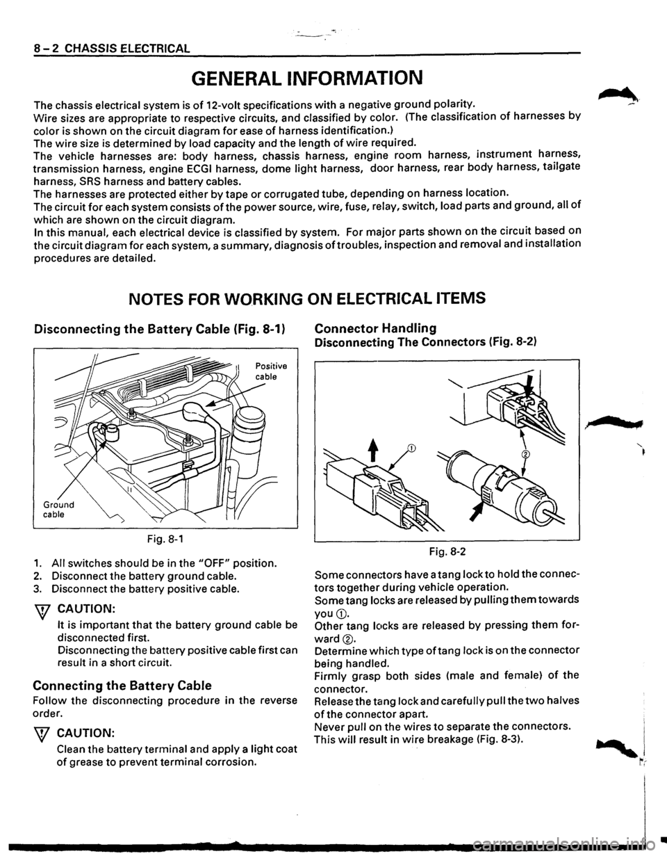
Disconnecting the Battery Cable (Fig. 8-1)
Ground cable
Fig. 8-1
1. All switches should be in the "OFF" position.
2. Disconnect the battery ground cable.
3. Disconnect the battery positive cable.
W CAUTION:
It is important that the battery ground cable be
disconnected first.
Disconnecting the battery positive cable first can
result in a short circuit.
Connecting the Battery Cable
Follow the disconnecting procedure in the reverse
order.
\V CAUTION:
Clean the battery terminal and apply a light coat
of grease to prevent terminal corrosion.
Connector Handling
Disconnecting The Connectors (Fig. 8-2)
Fig. 8-2
Some connectors have a tang lock to hold the connec
tors together during vehicle operation.
Some tang locks are released by pulling them towards
you
G).
Other tang locks are released by pressing them for
ward®.
Determine which type oftang lock is on the connector
being handled.
Firmly grasp both sides (male and female)
of the
connector. Release the tang lock and carefully pull the
two halves
of the connector apart.
Never pull on the wires
to separate the connectors.
This
will result in wire breakage (Fig. 8-3).
.,
..
Page 1198 of 1928
8-8 CHASSIS ELECTRICAL
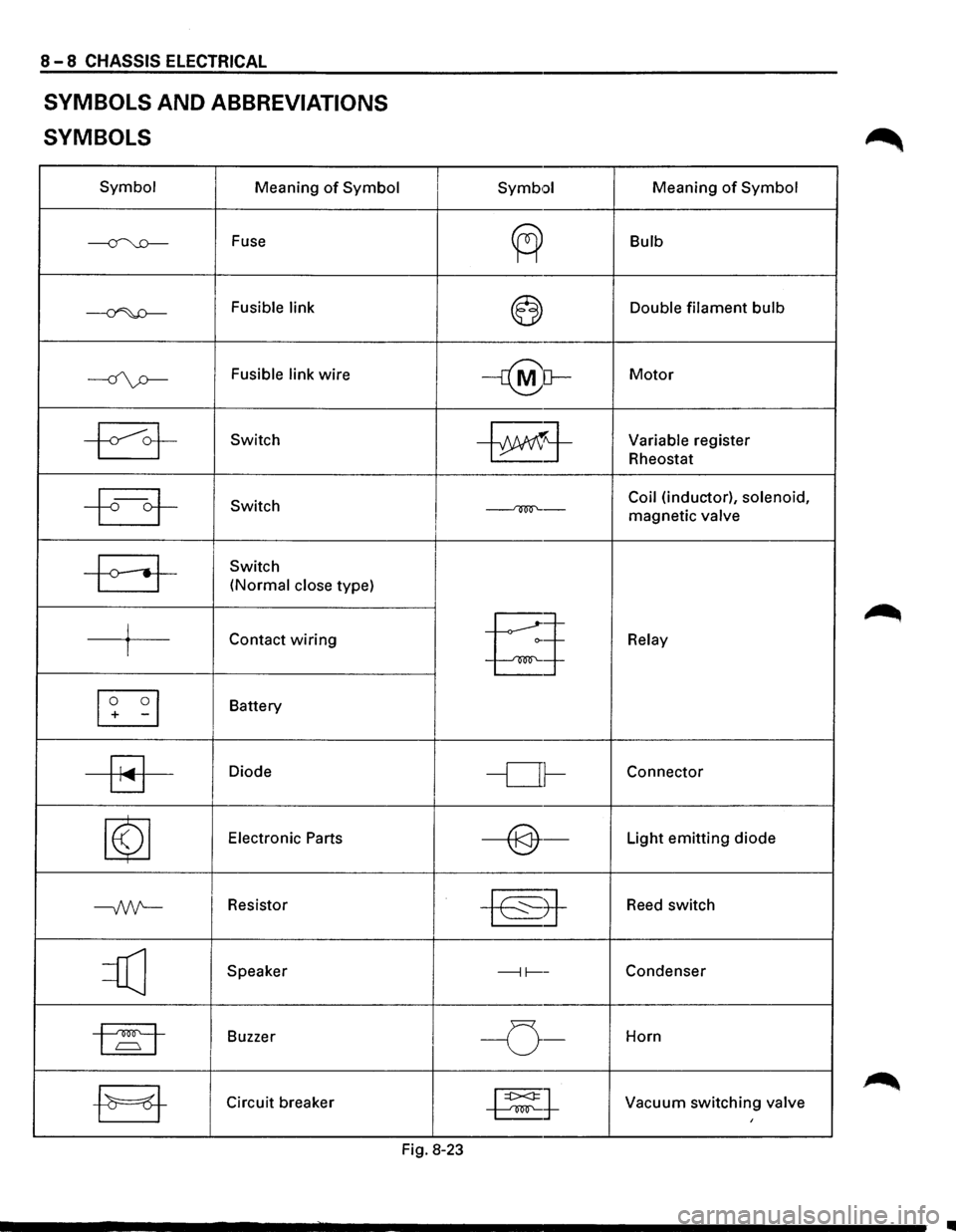
SYMBOLS AND ABBREVIATIONS
SYMBOLS
Symbol Meaning of Symbol
~ Fuse
~ Fusible link
----if\p-Fusible link wire
~ Switch
~ Switch
-a-
Switch
(Normal close type)
j Contact wiring I
[I] -I
Battery
~
Diode
~
Electronic Parts
--Nt-Resistor
=Q] Speaker
1~1 Buzzer I
-EJ-Circuit breaker
I Symb•:>l Meaning of Symbol
~
Bulb
~ Double filament bulb
-r@[}-Motor
~j-Variable register
Rheostat
Coil (inductor), solenoid,
~-magnetic valve I
§
Relay
-or-Connector
----@-Light emitting diode
~8-
Reed switch
---11----Condenser
I -o-Horn
~t Vacuum switching valve I
Fig. 8-23
•