battery ISUZU TROOPER 1995 Workshop Manual
[x] Cancel search | Manufacturer: ISUZU, Model Year: 1995, Model line: TROOPER, Model: ISUZU TROOPER 1995Pages: 1928
Page 1257 of 1928
•
•
•
•
•
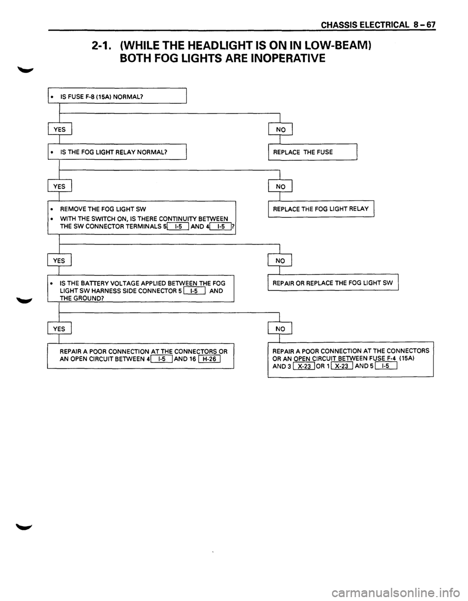
CHASSIS ELECTRICAL 8-67
2-1. (WHILE THE HEADLIGHT IS ON IN LOW-BEAM}
BOTH FOG LIGHTS ARE INOPERATIVE
IS FUSE F-8 (15A) NORMAL? I
I
I I
YES I NO I
I j
IS THE FOG LIGHT RELAY NORMAL? I REPLACE THE FUSE I
I
I j
YES I NO I
I I
REMOVE THE FOG LIGHT SW REPLACE THE FOG LIGHT RELAY I
WITH THE SWITCH ON, IS THERE CONTINUITY BETWEEN
THE SW CONNECTOR TERMINALS sc:::E[J AND 4[}[]7
I
I I
YES I NO j
I J
IS THE BATTERY VOLTAGE APPLIED BETWEEN THE FOG REPAIR OR REPLACE THE FOG LIGHT sw I
LIGHT SW HARNESS SIDE CONNECTOR sill] AND THE GROUND?
I
I I
YES I NO I
I I
REPAIR A POOR CONNECTION AT THE CONNECTORS OR REPAIR A POOR CONNECTION AT THE CONNECTORS
AN OPEN CIRCUIT BETWEEN 4[}[]AND 16 [[ill OR AN OPEN CIRCUIT BETWEEN FUSE F-4 (15AI
AND 31 x-23 loR 1 Wi] AND s DD
Page 1259 of 1928
LIGHTING SWITCH (COMBINATION
SWITCH)
The lighting switch has OFF, PARKING and HEAD
LIGHT positions. The Parking position is used to light
up the front side marker light, parking light, taillight,
license
plate light, and each illumination light. When
the headlight position, the headlight, in addition
to all
the lights mentioned above, is turned on through the
lighting relay.
CHASSIS ELECTRICAL 8-69
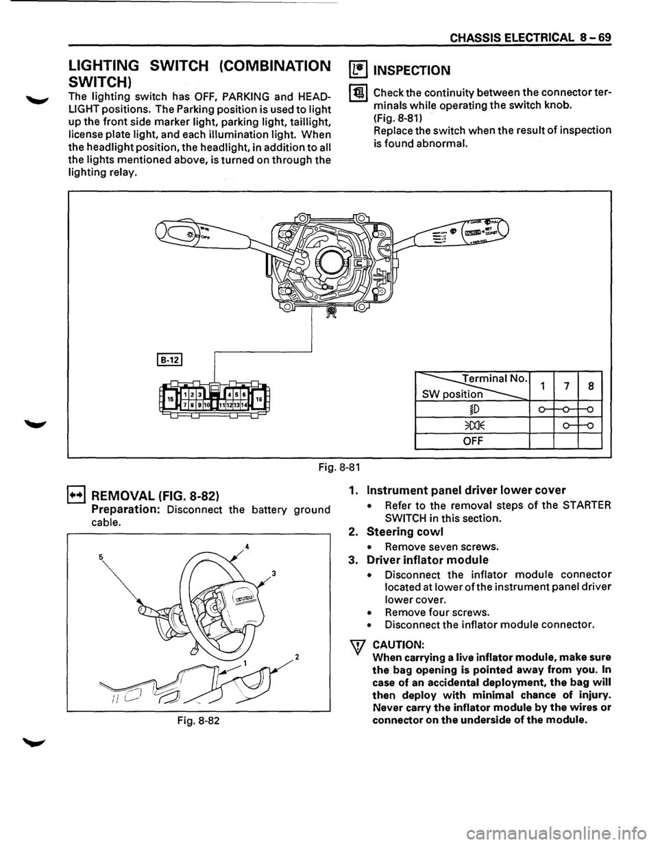
~ INSPECTION
I til Check the continuity between the connector ter
minals
while operating the switch knob.
(Fig. 8-81)
Replace the switch when the result
of inspection
is found abnormal.
Terminal No.
SW position 1 7 8
~D
OFF
Fig. 8-81
B REMOVAL (FIG. 8-82)
Preparation: Disconnect the battery ground
cable.
4
2
Fig. 8-82 1.
Instrument panel driver lower cover
• Refer to the
removal steps of the STARTER
SWITCH
in this section.
2.
Steering cowl
• Remove seven screws.
3.
Driver inflator module
• Disconnect the inflator module connector
located at lower
oft he instrument panel driver
lower cover.
• Remove four screws.
• Disconnect the inflator module connector.
W CAUTION:
When carrying a live inflator module. make sure
the bag opening is pointed away from you. In
case of an accidental deployment, the bag will
then deploy with minimal chance of injury.
Never carry
the inflator module by the wires or
connector on the underside of the module.
Page 1261 of 1928
DIMMER·PASSING SWITCH (COMBI
NATION SWITCH)
The headlight beams can be turned to high and low
alternately by pulling the switch lever up to the limit.
Also, the passing light can be flashed by operating the
switch lever within the range before the dimmer
switch has been changed over. The switch lever
returns automatically to its original position.
CHASSIS ELECTRICAL 8 -71
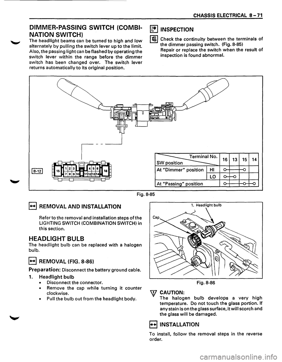
~ INSPECTION
lt!l Check the continuity between the terminals of
the dimmer passing switch. (Fig. 8-85)
Repair
or replace the switch when the result of
inspection is found abnormal.
~· s 16 13 15 14
At "Dimmer" position HI ~ ~ -
LO o-f-o
At "Passing" position ~ ~ ~
Fig.
8-85
E] REMOVAL AND INSTALLATION
Refer to the removal and installation steps oft he
LIGHTING SWITCH (COMBINATION SWITCH) in
this section.
HEADLIGHT BULB
The headlight bulb can be replaced with a halogen
bulb.
E] REMOVAL (FIG. 8-86)
Preparation: Disconnect the battery ground cable.
1. Headlight bulb
• Disconnect the connector.
• Remove the cap while turning it counter
clockwise.
• Pull the bulb out from the headlight body.
1. Headlight bulb
Fig. 8-86
W CAUTION:
The halogen bulb develops a very high
temperature. Do not touch the glass portion. If
any stain is on the glass surface, it will scorch and
the glass will be damaged.
B INSTALLATION
To install, follow the removal steps in the reverse
order.
Page 1262 of 1928
8 -72 CHASSIS ELECTRICAL
HEADLIGHT
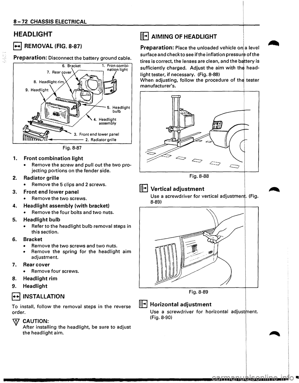
E) REMOVAL (FIG. 8-87)
Preparation: Disconnect the battery ground cable.
Fig. 8-87
1. Front combination light
• Remove the screw and pull out the two pro
jecting
portions on the fender side.
2. Radiator grille
• Remove the 5 clips and 2 screws.
3. Front end lower panel
• Remove the two screws.
4. Headlight assembly (with bracket)
• Remove the four bolts and two nuts.
5. Headlight bulb
• Refer to the headlight bulb removal steps in
this section.
6. Bracket
• Remove the two screws and two nuts.
• Remove the spring for the headlight aim
adjustment.
7. Rear cover
• Remove four screws.
8. Headlight rim
9. Headlight
E3 INSTALLATION
To install, follow the removal steps in the reverse
order.
W CAUTION:
After installing the headlight, be sure to adjust
the headlight aim.
(E AIMING OF HEADLIGHT
Preparation: Place the unloaded vehicle on a level
surface and check to see ifthe inflation pressur oft he
tires is correct, the lenses are clean, and the b ttery is
sufficiently charged.
Adjust the aim with th head
light tester, if necessary. (fig. 8-88)
When adjusting,
follow the procedure of th tester
manufacturer's.
Fig. 8-88
1~1 .... 1 Vertical adjustment
Use a screwdriver for vertical adjustmen . (Fig.
8-89)
Fig. 8-89
m .... l Horizontal adjustment
Use a screwdriver for horizontal adjust ent.
(Fig.
8-90)
..
Page 1263 of 1928
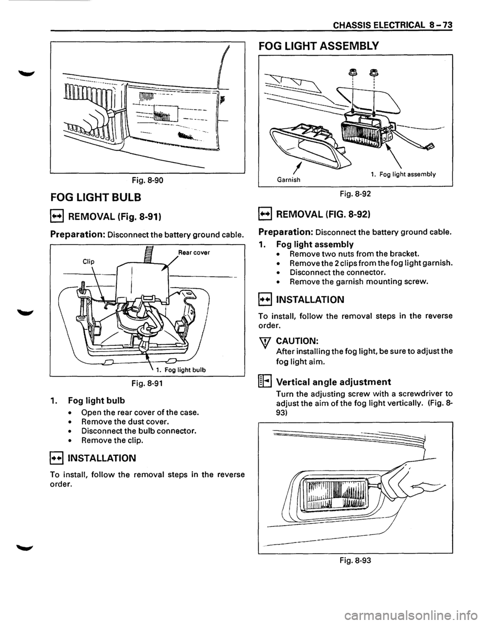
CHASSIS ELECTRICAL 8-73
FOG LIGHT ASSEMBLY
~ I : I
Fig. 8-90 Garnish 1. Fog light assembly
FOG LIGHT BULB Fig. 8-92
B REMOVAL (Fig. 8-91) B REMOVAL (FIG. 8-92)
Preparation: Disconnect the battery ground cable. Preparation: Disconnect the battery ground cable.
Fig. 8-91
1. Fog light bulb
• Open the rear cover of the case.
• Remove the dust cover.
• Disconnect the bulb connector.
• Remove the clip.
EJINSTALLATION
To install, follow the removal steps in the reverse
order.
1. Fog light assembly
• Remove two nuts from the bracket.
• Remove the 2 clips from the fog light garnish.
• Disconnect the connector.
• Remove the garnish mounting screw.
B INSTALLATION
To install, follow the removal steps in the reverse
order.
\V CAUTION:
After installing the fog light, be sure to adjust the
fog light aim.
1~1 ... 1 Vertical angle adjustment
Turn the adjusting screw with a screwdriver to
adjust the aim of the fog light vertically. (Fig. 8-
93)
1r~~·~··.l J.li' . WlliJ
-'I IJIJJ
---
-------
Fig. 8-93
Page 1264 of 1928
8-74 CHASSIS ELECTRICAL
FOG LIGHT SWITCH
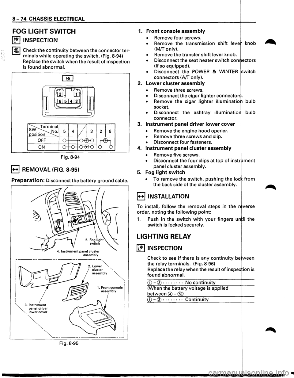
~ INSPECTION
I tgj Check the continuity between the connector ter
minals
while operating the switch. (Fig. 8-94)
Replace the switch when the result of inspection
is found abnormal.
ru~
IT
2 [II
161514131
c-
Fig. 8-94
B REMOVAL (FIG. 8-95)
TI ';
Preparation: Disconnect the battery ground cable.
Fig.
8-95
I I 1. Front console I assembly
1. Front console assembly
• Remove four screws.
• Remove the transmission shift leve knob
(M!r only).
• Remove the transfer shift lever knob.
• Disconnect the seat heater switch con ectors
(If so equipped).
• Disconnect the POWER & WINTER switch
connectors
(A/T only).
2.
Lower cluster assembly
• Remove three screws.
• Disconnect the cigar lighter connector .
• Remove the cigar lighter illuminatio bulb
socket.
• Disconnect the ashtray illuminatio bulb
connector.
3.
Instrument panel driver lower cover
• Remove the engine hood opener.
• Remove three screws and clip.
• Disconnect four fasteners.
4.
Instrument panel cluster assembly
• Remove five screws.
• Disconnect the four clips at top of instr ment
panel cluster assembly.
5. Fog
light switch
• To remove the switch, pushing the loc from
the back side of the cluster assembly.
B INSTALLATION
To install, follow the removal steps in the r verse
order, noting the
following point:
1. Push in the switch with your fingers un il the
switch is locked securely.
LIGHTING RELAY
~ INSPECTION
Check to see if there is any continuity be ween
the relay terminals. (Fig.
8-96)
Replace the relay when the result of in spec ion is
found abnormal.
CD-3 · · · · • · · · No continuit
(When the battery voltage is applied
between
4 -s)
•
Page 1265 of 1928
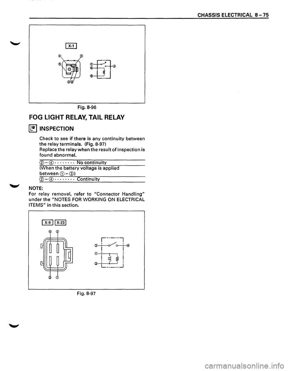
Fig. 8-96
FOG LIGHT RELAY, TAIL RELAY
~ INSPECTION
Check to see if there is any continuity between
the relay terminals. (Fig. 8-97)
Replace the relay
when the result of inspection is
found abnormal.
®-@ · · · · · · · · No continuity
(When the battery voltage is applied
between
CD-@)
®-@ · · · · · · · · Continuity
NOTE:
For relay removal, refer to "Connector Handling"
under the "NOTES FOR WORKING ON ELECTRICAL
ITEMS"
in this section.
Fig. 8-97
CHASSIS ELECTRICAL 8-75
Page 1266 of 1928
8 -76 CHASSIS ELECTRICAL
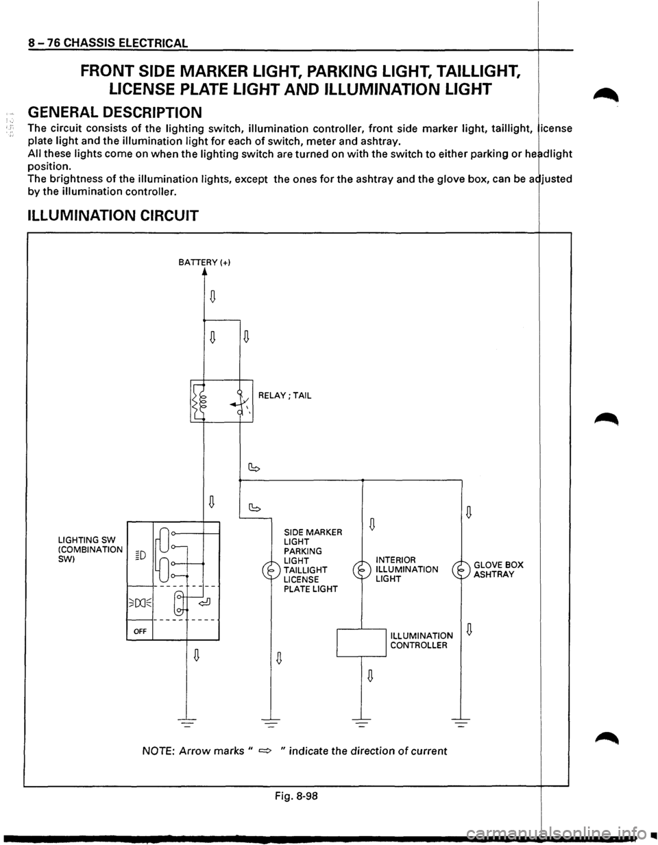
FRONT SIDE MARKER LIGHT, PARKING LIGHT, TAILLIGHT,
LICENSE
PLATE LIGHT AND ILLUMINATION LIGHT
· GENERAL DESCRIPTION ;·. · ;. The circuit consists of the lighting switch, illumination controller, front side marker light, taillight, icense
plate light and the illumination light for each of switch, meter and ashtray.
All these lights come on when the lighting switch are turned on with the switch to either parking or he~dlight
position.
The brightness
of the illumination lights, except the ones for the ashtray and the glove box, can be a< justed
by the
illumination controller.
ILLUMINATION CIRCUIT
LIGHTING SW (COMBINATION
SW)
BATTERY(+)
n n
I~
w ~=o-t--+
f------
;;ooE ~-<0
f-------
OFF
RELAY; TAIL
SIDE
MARKER LIGHT
PARKING
LIGHT
TAILLIGHT
LICENSE
PLATE LIGHT INTERIOR
ILLUMINATION
LIGHT
) )
ILLUMINATION n CONTROLLER c__-,-----'
NOTE: Arrow marks " =:> " indicate the direction of current
Fig. 8-98
GLOVE BOX
ASHTRAY
1111
Page 1273 of 1928
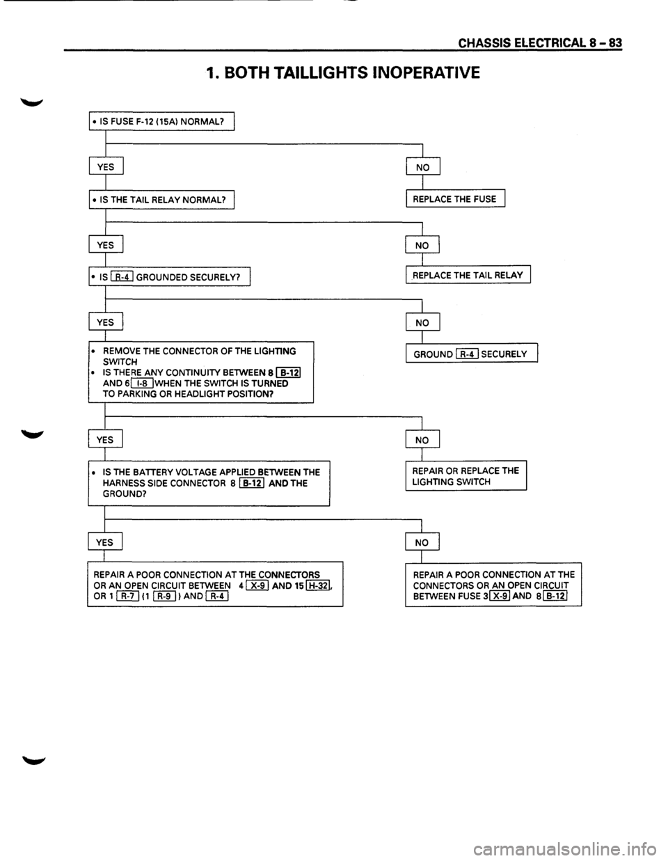
CHASSIS ELECTRICAL 8 -83
1. BOTH TAILLIGHTS INOPERATIVE
• IS FUSE F-12 (15Al NORMAL? I
I
I
I
YES I NO I
I I
• IS THE TAIL RELAY NORMAL? I REPLACE THE FUSE I
I
I
I
YES I NO I
I I
•
IS[&!] GROUNDED SECURELY? I REPLACE THE TAIL RELAY I
I
I
l
YES I NO I
I I
• REMOVE
THE CONNECTOR OF THE LIGHTING GROUND I R-41 SECURELY I SWITCH
• IS THERE ANY CONTINUITY BETWEEN 81 B-121
AND SIT[] WHEN THE SWITCH IS TURNED
TO PARKING OR HEADLIGHT POSITION?
l
I I
YES I NO I
I I
• IS
THE BATTERY VOLTAGE APPLIED BETWEEN THE REPAIR OR REPLACE THE I
HARNESS SIDE CONNECTOR Bl B-121 AND THE LIGHTING SWITCH
GROUND?
I
I I
YES
I NO I
I I
REPAIR
A POOR CONNECTION AT THE CONNECTORS REPAIR A POOR CONNECTION AT THE
OR AN OPEN CIRCUIT BETWEEN 41 X-91 AND 151 H-321. CONNECTORS OR AN OPEN CIRCUIT OR 1 [friJ ( 1 (K[]) AND[&!] BETWEEN FUSE 31 X-9IAND Bl B-121
Page 1275 of 1928
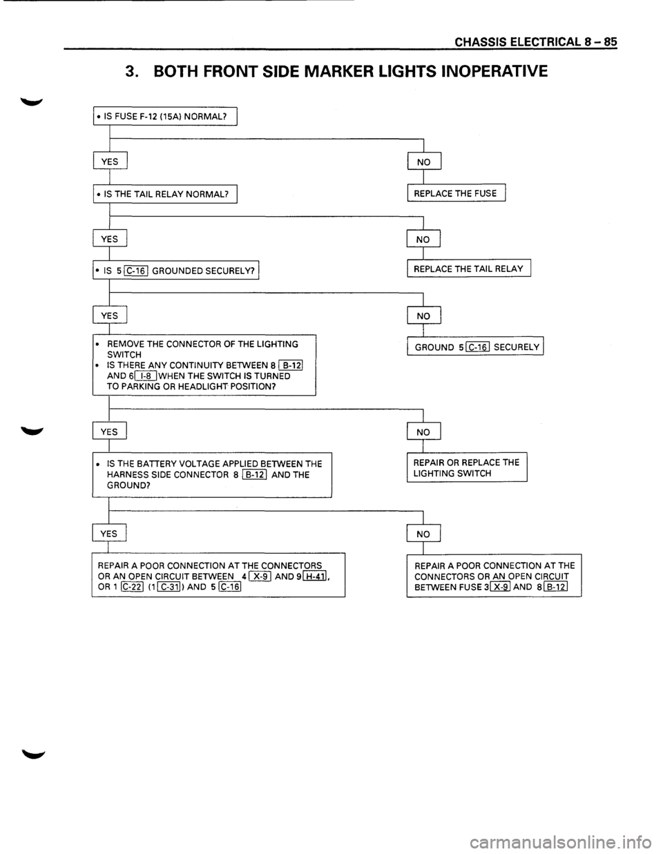
CHASSIS ELECTRICAL 8-85
3. BOTH FRONT SIDE MARKER LIGHTS INOPERATIVE
• IS FUSE F-12 (15Al NORMAL? I
l
I I
YES I NO I
I I
• IS THE TAIL RELAY NORMAL? I REPLACE THE FUSE I
l
I I
YES I NO I
I I
• IS sl C-161 GROUNDED SECURELY? I REPLACE THE TAIL RELAY I
I
I
I
YES I NO I
I I
• REMOVE THE CONNECTOR OF THE LIGHTING
GROUND slc-16l SECURELY I SWITCH
• IS
THERE ANY CONTINUITY BETWEEN Bl B-121 AND 6CI[JWHEN THE SWITCH IS TURNED TO PARKING OR HEADLIGHT POSITION?
I
I I
YES I NO I
I I
• IS THE BATTERY VOLTAGE APPLIED BETWEEN THE REPAIR OR REPLACE THE I
HARNESS SIDE CONNECTOR Bl B-121 AND THE LIGHTING SWITCH
GROUND?
I
I
I
YES I NO 1
I I
REPAIR A POOR CONNECTION AT THE CONNECTORS REPAIR A POOR CONNECTION AT THE
OR AN OPEN CIRCUIT BETWEEN 41 X-91 AND 91 H-411, CONNECTORS OR AN OPEN CIRCUIT OR 1 IC-221 111 C-311 lAND siC-161 BETWEEN FUSE 31 X-91 AND al B-121