battery ISUZU TROOPER 1995 Workshop Manual
[x] Cancel search | Manufacturer: ISUZU, Model Year: 1995, Model line: TROOPER, Model: ISUZU TROOPER 1995Pages: 1928
Page 1315 of 1928
HORN SWITCH
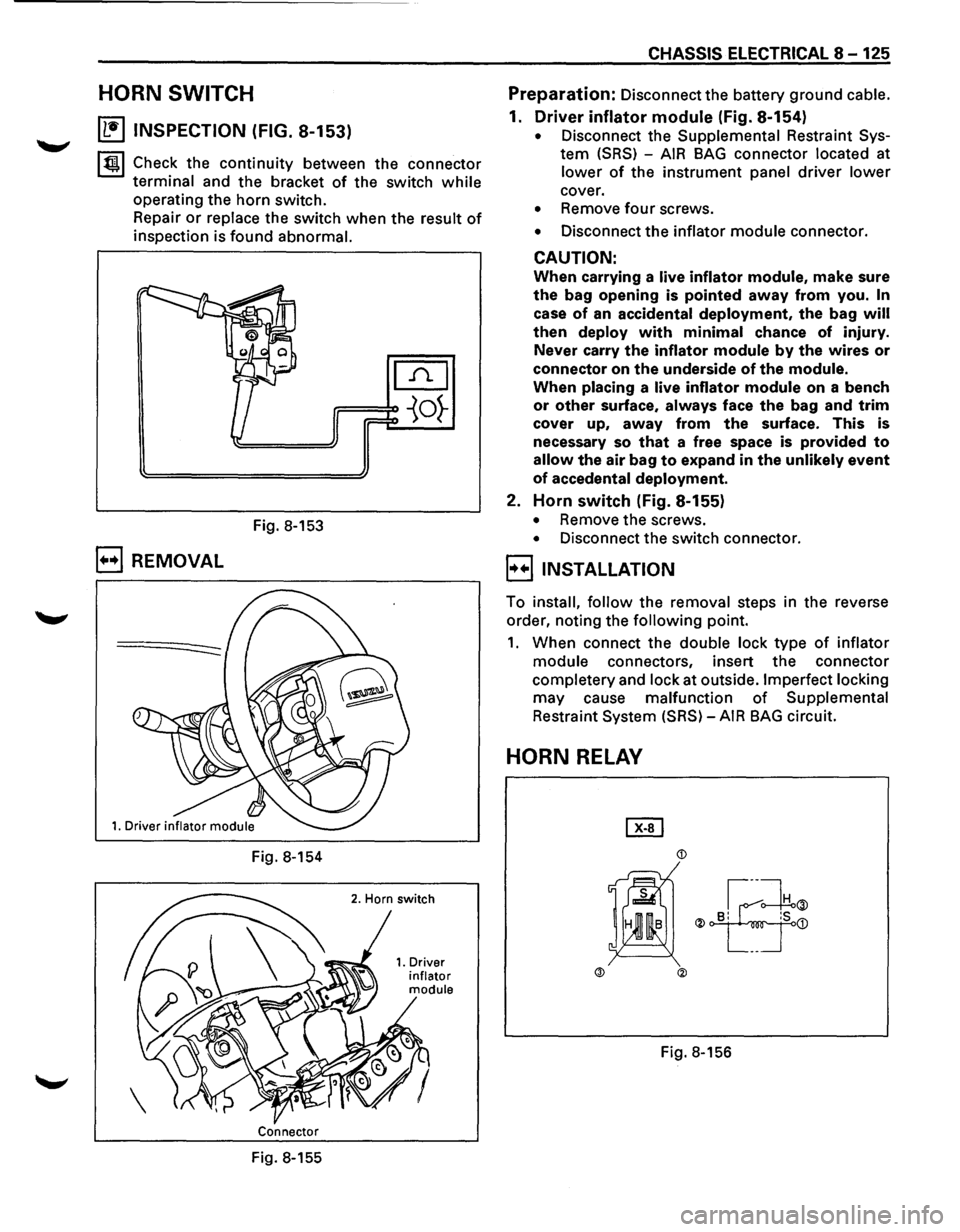
~ INSPECTION (FIG. 8-153)
~~~ Check the continuity between the connector
terminal and the bracket of the switch while
operating the horn switch.
Repair
or replace the switch when the result of
inspection is found abnormal.
Fig. 8-153
B REMOVAL
Fig. 8-154
Connector
Fig. 8-155
CHASSIS ELECTRICAL 8-125
Preparation: Disconnect the battery ground cable.
1. Driver inflator module (Fig. 8-154)
• Disconnect the Supplemental Restraint Sys
tem (SRS) -AIR BAG connector located at
lower of the instrument panel driver lower
cover.
• Remove four screws.
• Disconnect the inflator module connector.
CAUTION:
When carrying a live inflator module, make sure
the bag opening is pointed away from you. In
case of an accidental deployment, the bag will
then deploy with minimal chance of injury.
Never carry
the inflator module by the wires or
connector on the underside of the module.
When placing a live inflator module on a bench
or other surface, always face the bag and trim
cover up, away from the surface. This is
necessary so
that a free space is provided to
allow the air bag to expand in the unlikely event
of accedental deployment.
2. Horn switch (Fig. 8-155)
• Remove the screws.
• Disconnect the switch connector.
l·u·IINSTALLATION
To install, follow the removal steps in the reverse
order, noting the
following point.
1. When connect the double lock type of inflator
module connectors, insert the connector
completery and lock at outside. Imperfect locking
may cause malfunction of Supplemental
Restraint System (SRS)-AIR BAG circuit.
HORN RELAY
Page 1316 of 1928
8-126 CHASSIS ELECTRICAL
~ INSPECTION
lt!ll Check to see if there is any continuity between
the
relay terminals. (Fig. 8-156)
Replace the
relay when the result of inspection
is
found abnormal.
®-@ ....... No continuity
(When the battery voltage is applied between
CORNERING LIGHT RELAY
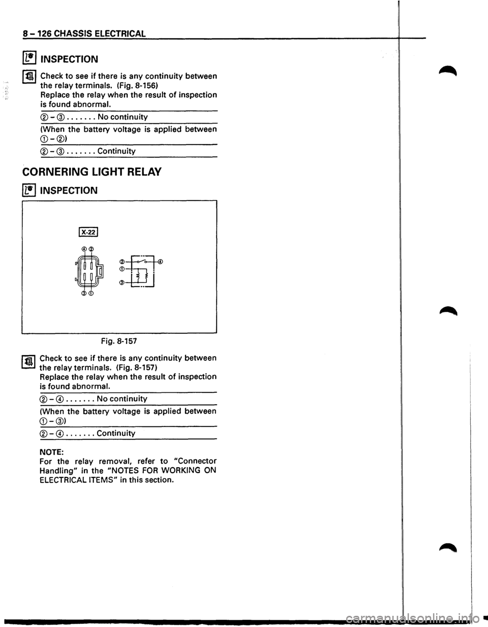
~ INSPECTION
Fig. 8-157
r1il Check to see if there is any continuity between
1.!!!.1 the relay terminals. (Fig. 8-157)
Replace the relay when the result of inspection
is
found abnormal.
®-@ ....... No continuity
(When the battery voltage is applied between
NOTE:
For the relay removal, refer to "Connector
Handling" in the "NOTES FOR WORKING ON
ELECTRICAL ITEMS" in this section.
•
Page 1324 of 1928
![ISUZU TROOPER 1995 Workshop Manual 8-134 CHASSIS ELECTRICAL
STARTER SWITCH
Refer to "START AND CHARGING" of this section.
DOOR SWITCH
(1!] INSPECTION
Push o
[]:!]
Connector No. IR-11IIB-22IIB-35l Switch
operation Terminal 1 B](/img/61/57183/w960_57183-1323.png "ISUZU TROOPER 1995 Workshop Manual 8-134 CHASSIS ELECTRICAL
STARTER SWITCH
Refer to \"START AND CHARGING\" of this section.
DOOR SWITCH
(1!] INSPECTION
Push o
[]:!]
Connector No. IR-11IIB-22IIB-35l Switch
operation Terminal 1 B")
8-134 CHASSIS ELECTRICAL
STARTER SWITCH
Refer to "START AND CHARGING" of this section.
DOOR SWITCH
(1!] INSPECTION
Push o
[]:!]
Connector No. IR-11IIB-22IIB-35l Switch
operation Terminal 1 Body
Push
Release
Fig. 8-164
I t!ll Check to see if there is any continuity between
the
terminals and the body while operating the
door switch. (Fig. 8-164)
Repair
or replace the switch, when the result of
inspection is found abnormal.
B REMOVAL (FIG. 8-165)
Preparation: Disconnect the battery ground cable.
1. Door switch
Fig. 8-165
1.
Door switch
• Remove the screw.
• Disconnect the connector of the switch.
B INSTALLATION
To install, follow the removal steps in the averse
order.
TAILGATE SWITCH
(b!] INSPECTION
Release
Fig. 8-166
I til Check to see if there is any continuity b tween
the
terminals and the body while operati g the
tailgate switch. (Fig. 8-166)
Repair
or replace the tailgate switch wh n the
result of inspection is found abnormal.
B REMOVAL (FIG. 8-167)
Preparation: Disconnect the battery ground cable.
Fig. 8-167
1.
Tailgate switch
• Remove the screws.
• Disconnect the connector of the switch.
•
Page 1325 of 1928
EJ INSTALLATION
To install, follow the removal steps in the reverse
order.
DOME LIGHT BULB
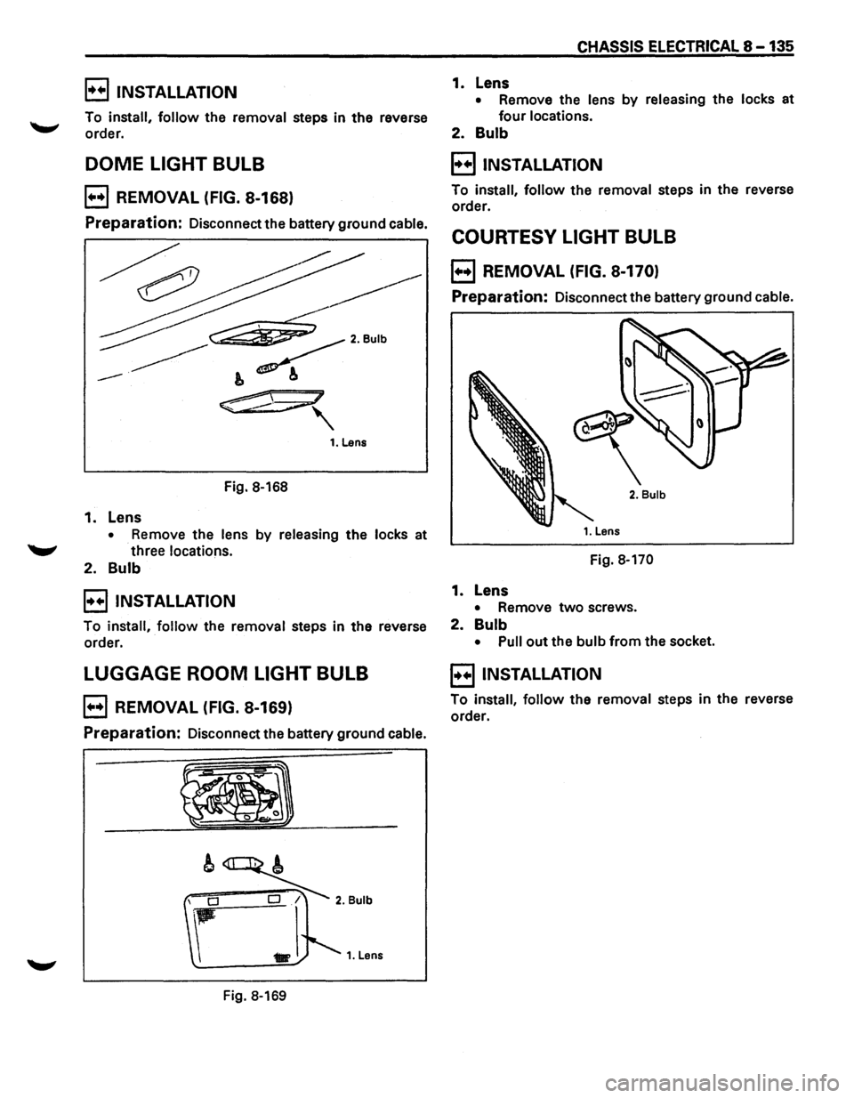
B REMOVAL (FIG. 8-168)
Preparation: Disconnect the battery ground cable.
Fig. 8-168
1. Lens
• Remove the lens by releasing the locks at
"-" three locations.
2. Bulb
B INSTALLATION
To install, follow the removal steps in the reverse
order.
LUGGAGE ROOM LIGHT BULB
B REMOVAL (FIG. 8-169)
Preparation: Disconnect the battery ground cable.
Fig. 8-169
CHASSIS ELECTRICAL 8 -135
1. Lens
• Remove the lens by releasing the locks at
four locations.
2. Bulb
B INSTALLATION
To install, follow the removal steps in the reverse
order.
COURTESY LIGHT BULB
B REMOVAL (FIG. 8-170)
Preparation: Disconnect the battery ground cable.
2. Bulb
Fig. 8-170
1. Lens
• Remove two screws.
2. Bulb
• Pull out the bulb from the socket.
E) INSTALLATION
To install, follow the removal steps in the reverse
order.
Page 1326 of 1928
8 -136 CHASSIS ELECTRICAL
MAP LIGHT SWITCH/BULB
~ INSPECTION
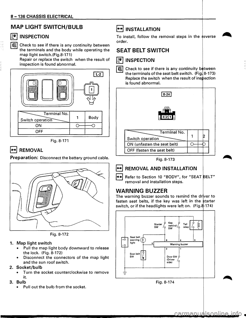
~~~ Check to see if there is any continuity between
the terminals and the body while operating the
map light switch.(Fig.8-171)
Repair
or replace the switch when the result of
inspection is found abnormal.
I" ~ [IT]
ron
0~/~ ~
'
~· 1 Body
n
ON 0 {)
OFF
Fig. 8-171
B REMOVAL
E) INSTALLATION
To install, follow the removal steps in the everse
order.
SEAT BELT SWITCH
~ INSPECTION
I~ l Check to see if there is any continuity b tween
the terminals of the seat belt switch. (Fig 8-173)
Replace the switch when the
result of ins ection
is found abnormal.
Switch operation
ON (unfasten the seat belt)
OFF (fasten the seat belt)
Preparation: Disconnect the battery ground cable. Fig. 8-173
Fig. 8-172
1.
Map light switch
• Pull the map light body downward to release
the
lock. (Fig. 8-172)
• Disconnect the connectors of the map light
and the sun roof switch.
2. Socket/bulb
• Turn the socket counterclockwise to remove
it.
3.
Bulb
• Pull out the bulb from the socket.
B REMOVAL AND INSTALLATION
1++1 Refer to Section 10 "BODY", for "SEAT ELT"
removal and installation steps.
WARNING BUZZER
The warning buzzer sounds to remind the dr ver to
fasten seat belts, if the key was left in the tarter
switch,
or if the headlights were left on. (Fig. -174)
Seat belt warning light
Seat belt
sw
Starter sw
8
Warning buzzer
DoorSW (Driver
side)
Fig. 8-174
..
Page 1329 of 1928
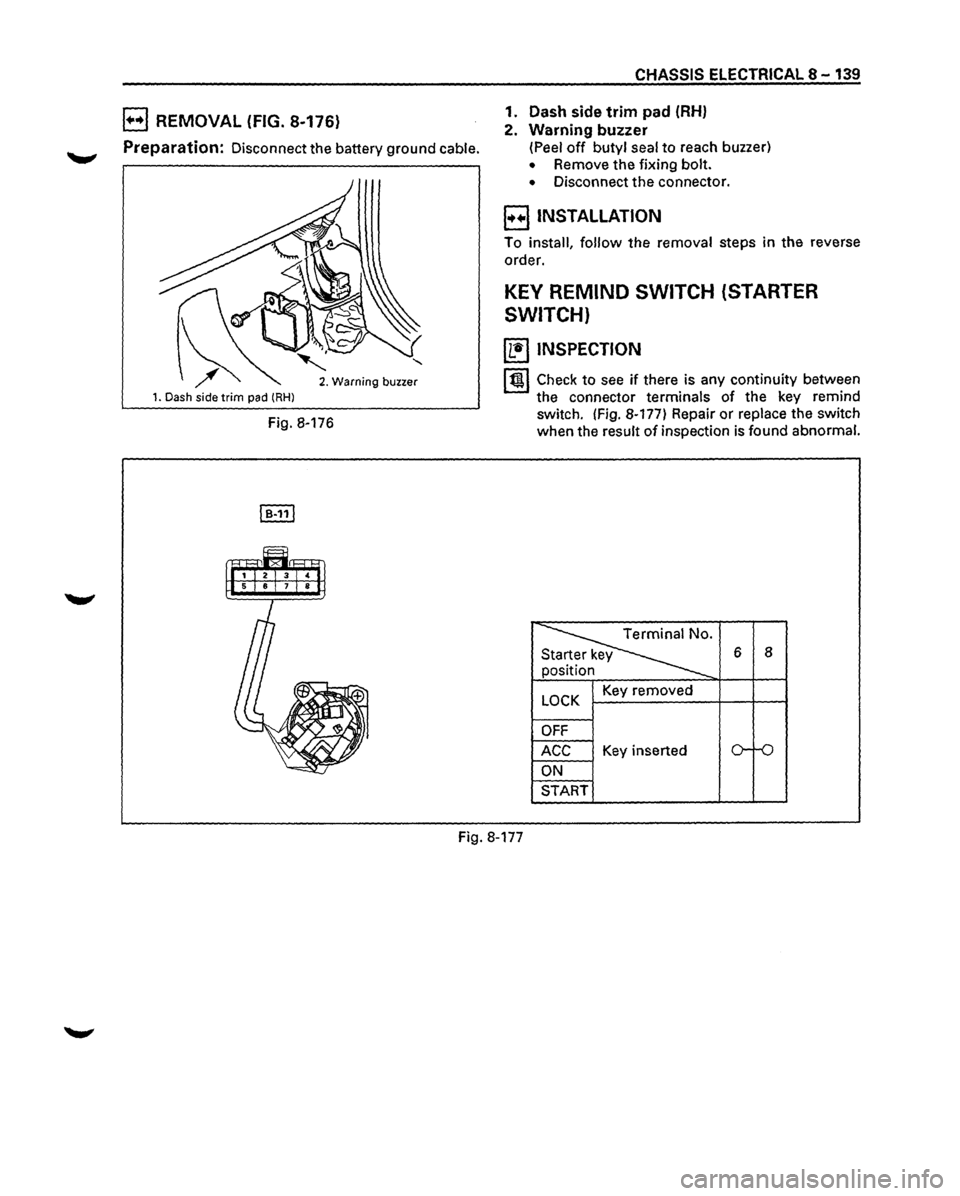
B REMOVAL (FIG. 8-176)
Preparation: Disconnect the battery ground cable.
1. Dash side trim pad (RHl
' 2. Warning buzzer
Fig. 8-176
CHASSIS ELECTRICAL 8-139
1. Dash side
trim pad (RH)
2. Warning buzzer
(Peel off butyl seal to reach buzzer)
• Remove the fixing bolt.
• Disconnect the connector.
E) INSTALLATION
To install, follow the removal steps in the reverse
order.
KEY REMIND SWITCH (STARTER
SWITCH)
~ INSPECTION
I t!tl Check to see if there is any continuity between
the connector terminals of the key remind
switch. (Fig. 8-177) Repair
or replace the switch
when the result
of inspection is found abnormal.
~
6 8
n
y
LOCK Key removed
OFF
ACC Key inserted o-ro
ON
START
Fig. 8-177
Page 1330 of 1928
._, '•'
8 -140 CHASSIS ELECTRICAL
E) REMOVAL AND INSTALLATION E) REMOVAL (FIG. 8-180)
l••l Refer to "START AND CHARGING" in this sec-Preparation: Disconnect the battery ground cable.
tion for starter switch removal and installation
steps.
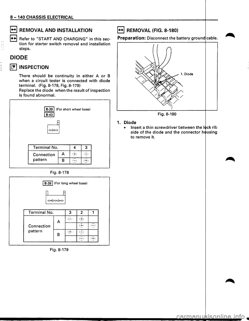
DIODE
~ INSPECTION
There should be continuity in either A or B
when a circuit tester is connected with diode
terminal. (Fig. 8-178, Fig. 8-179)
Replace the diode when the result
of inspection
is found abnormal.
I B-391 (For short wheel base)
I B-431
Terminal No. 4 3
Connection A t'+i i-)
pattern B I.=,J 1+1
Fig.
8-178
I B-391 (For long wheel base)
Terminal No. 3 2
A (-) 1.!,>
Connection (~!
pattern 1+1 {-) B (-!
Fig. 8-179
1
'.-::::1
(~)
Fig. 8-180
1. Diode
• Insert a thin screwdriver between the I ck rib
side
of the diode and the connector h using
to remove it.
..
Page 1332 of 1928
8-142 CHASSIS ELECTRICAL
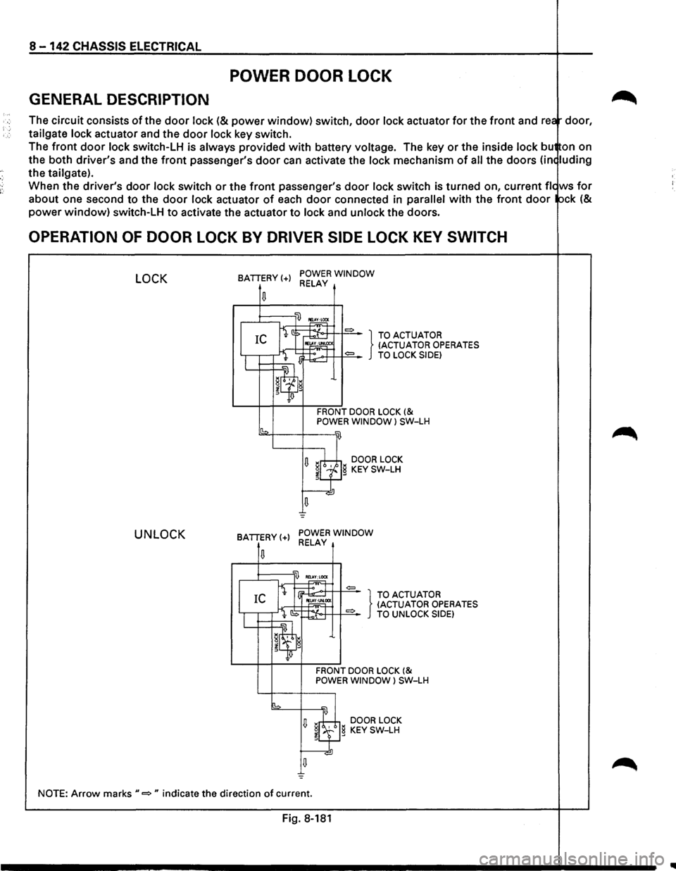
POWER DOOR LOCK
GENERAL DESCRIPTION
The circuit consists of the door lock (& power window) switch, door lock actuator for the front and rea door,
tailgate
lock actuator and the door lock key switch.
The
front door lock switch-LH is always provided with battery voltage. The key or the inside lock bu on on
the both driver's and the
front passenger's door can activate the lock mechanism of all the doors (in< luding
the tailgate).
When the driver's
door lock switch or the front passenger's door lock switch is turned on, current fie ws for
about one second to the door lock actuator of each door connected in parallel with the front door ock (&
power window) switch-LH to activate the actuator to lock and unlock the doors.
OPERATION OF DOOR LOCK BY DRIVER SIDE LOCK KEY SWITCH
LOCK
UNLOCK
BATTERY(+) POWER WINDOW RELAY
.....-1::::::;---'li) ~
fi ::> ~ = } TO ACTUATOR IC IE~CC (ACTUATOR OPERATES
I l lj~:.-.>+T++==-TO LOCK SIDE)
W=~~~~'l g
Jlf!
FRONT DOOR LOCK (& POWER WINDOW l SW-LH
sb2-f---+---w
U ~rh;±,i DOOR LOCK ~LfJg KEY SW-LH
u =
BATTERY(+) POWER WINDOW RELAY
,..,~T =
I IEl.
CS ~:t-o·++ 1+==-TO UNLOCK SIDE)
IL...t=:t=~~w.~ g
~q;J
FRONT DOOR LOCK (& POWER WINDOW) SW-LH
[b =
U ~8 DOOR LOCK
~l.f} KEY SW-LH
NOTE: Arrow marks"=" indicate the direction of current.
Fig. 8-181
IIIII
Page 1333 of 1928
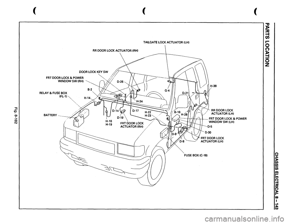
"T1 !0 (X) I ... (X) N
(
RR
DOOR
LOCK
ACTUATOR
(RHI
DOOR
LOCK
KEY
SW
"-
FRT
DOOR
LOCK
& POWER
WINDOW SW
(RHI
RELAY
& FUSE
BOX (FL-11~
BATTERY
' ,,
( TAILGATE
LOCK
ACTUATOR
(LHI
RR
DOOR
LOCK
ACTUATOR
(LHI
h.=
I //If/:
I
FRT
DOOR
LOCK
& POWER
WINDOW
SW
(LHI
FRT
DOOR
LOCK
ACTUATOR
(LHI
FUSE
BOX
(C-181
(
~ ~ r-0 n ~ 0
2
(") J: )> en
en (i) m rm ~ :a g reo I ...a t
Page 1337 of 1928
•
•
•
•
•
CHASSIS ELECTRICAL 8-147
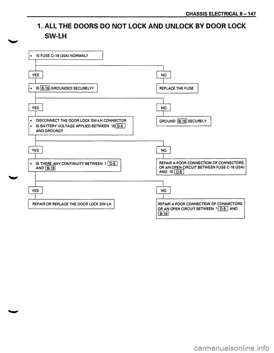
1. ALL THE DOORS DO NOT LOCK AND UNLOCK BY DOOR LOCK
SW-LH
IS FUSE C-18 (20Al NORMAL? I
I
YES I NO I
I
IS I
B-181 GROUNDED SECURELY? I REPLACE THE FUSE I
I
YES
j NO I
l
DISCONNECT THE DOOR LOCK SW-LH CONNECTOR
GROUND IB-18ISECURELY
IS
BATTERY VOLTAGE APPLIED BETWEEN 10~
AND GROUND?
l
YES I NO I
l
IS THERE ANY CONTINUITY BETWEEN 11 D-5 I I REPAIR A POOR CONNECTION OF CONNECTORS
AND I B-181 OR AN OPEN CIRCUIT BETWEEN FUSE C-18 (20A)
AND 10 I D-51
I
YES I NO I
I
REPAIR
OR REPLACE THE DOOR LOCK SW-LH J REPAIR A POOR CONNECTION OF CONNECTORS
OR AN OPEN CIRCUIT BETWEEN 11 D-5 I AND
I B-181