lock ISUZU TROOPER 1995 Workshop Manual
[x] Cancel search | Manufacturer: ISUZU, Model Year: 1995, Model line: TROOPER, Model: ISUZU TROOPER 1995Pages: 1928
Page 752 of 1928
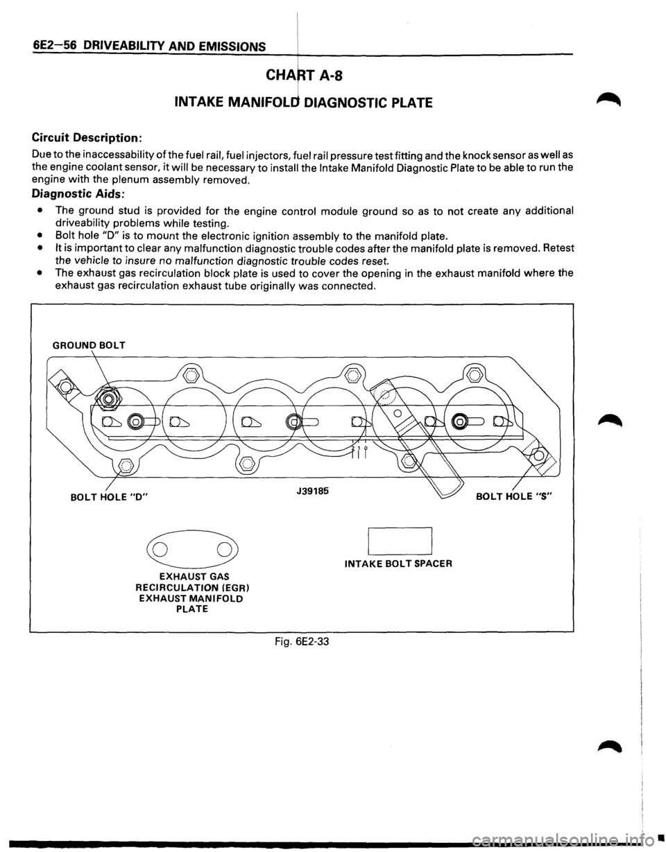
Circuit Description:
Due to the inaccessability of the fuel rail, fuel injectors, fuel rail pressure test fitting and the knock sensor as well as
the engine coolant sensor, it will be necessary to install the Intake Manifold Diagnostic Plate to be able to run the
engine with the
plenum assembly removed.
Diagnostic Aids:
• The ground stud is provided for the engine control module ground so as to not create any additional
driveability problems while
testing.
• Bolt hole "D" is to mount the electronic ignition assembly to the manifold plate.
• It
is important to clear any malfunction diagnostic trouble codes after the manifold plate is removed. Retest
the
vehicle to insure no malfunction diagnostic trouble codes reset.
• The exhaust gas recirculation block plate is used to cover the opening in the exhaust manifold where the
exhaust gas
recirculation exhaust tube originally was connected.
GROUND BOLT
~
EXHAUST GAS
RECIRCULATION
(EGR)
EXHAUST MANIFOLD PLATE
INTAKE BOLT SPACER
Fig. 6E2-33
•
Page 753 of 1928
DRIVEABILITY AND EMISSIONS 6E2-57
CHART A-8
INTAKE MANIFOLD DIAGNOSTIC PLATE
(INSTALLATION PROCEDURE)
NOTE: THE INTAKE MANIFOLD DIAGNOSTIC PLATE IS USED TO ALLOW THE ENGINE TO BE RUN WITH
THE COMMON CHAMBER ASSEMBLY REMOVED. IT IS NOT INTENDED TO ALLOW A TECHNICIAN
TO
DRIVE THE VEHICLE WITH THE INTAKE MANIFOLD PLATE INSTALLED.
INSTALLATION:
1. RELIEVE FUEL PRESSURE. REFER TO PAGE 3 OF 3 OF CHART A-7 OF THIS SECTION.
2. DISCONNECT NEGATIVE BATTERY CABLE.
3. REMOVE INTAKE PLENUM ASSEMBLY PER PROCEDURE IN SECTION C-2 FUEL METERING
SYSTEMS.
4. INSTALL MANIFOLD DIAGNOSTIC PLATE WITH GROUND BOLT TO THE REAR OF THE ENGINE.
INSTALL
GROUND WIRES TO BOLT.
5. USE THE SIX (6) BOLTS TO SECURE THE MANIFOLD PLATE TO THE INTAKE ASSEMBLY.
6. USE BOLT HOLE "D" TO SECURE THE ELECTRONIC IGNITION UNIT TO THE MANIFOLD PLATE.
7. INSTALL THE EXHAUST GAS RECIRCULATION BLOCK PLATE AT EXHAUST MANIFOLD.
8. TORQUE ALL FASTENERS TO 8-12 LB.FT. (11-16 N·m) SEE CAUTION.
CAUTION: OVER-TORQUING
THE INTAKE MANIFOLD PLATE MAY DAMAGE THE INTAKE MANIFOLD
PLATE'S SEALING SURFACE WHICH WILL RESULT IN AN "AIR LEAK" AT THE PLATE BASE
GASKET. THIS COULD RESULT IN A MISDIAGNOSIS OF A DRIVEABILITY PROBLEM.
STARTING THE VEHICLE WITH DIAGNOSTIC PLATE INSTALLED:
1. SET THE PLATE SLIDER TO POSITION "0".
2. USING A HAND HELD VACUUM PUMP APPLY 12-15 INCHES (34-52 kPa) OF VACUUM TO THE
MANIFOLD ABSOLUTE PRESSURE SENSOR AND THE FUEL PRESSURE CONTROL VALVE.
3. CRANK ENGINE AND ALLOW REVOLUTION PER MINUTE TO STABILIZE. RUN FOR 2-5 MINUTES.
4. MOVE SLIDER BAR TO POSITION "1" WHICH WILL ALLOW THE ENGINE TO IDLE AT 1000 TO 1200
REVOLUTION
PER MINUTE. THIS ALLOWS ANY NEEDED DIAGNOSTIC TEST TO BE PERFORMED.
5. POSITION TWO (2) WILL CAUSE THE ENGINE TO STALL. THIS IS TO ALLOWS THE TECHNICIAN
TO "STALL"
THE ENGINE FROM OUTSIDE OF THE VEHICLE.
INTAKE MANIFOLD DIAGNOSTIC
PLATE REMOVAL:
1. REVERSE THE ABOVE PROCEDURES USED IN THE INSTALLATION PROCEDURE.
2. BE SURE TO CLEAR ALL CODES AND CONFIRM VEHICLE IS OPERATING NORMALLY.
Page 754 of 1928
6E2-58 DRIVEABILITY AND EMISSIONS
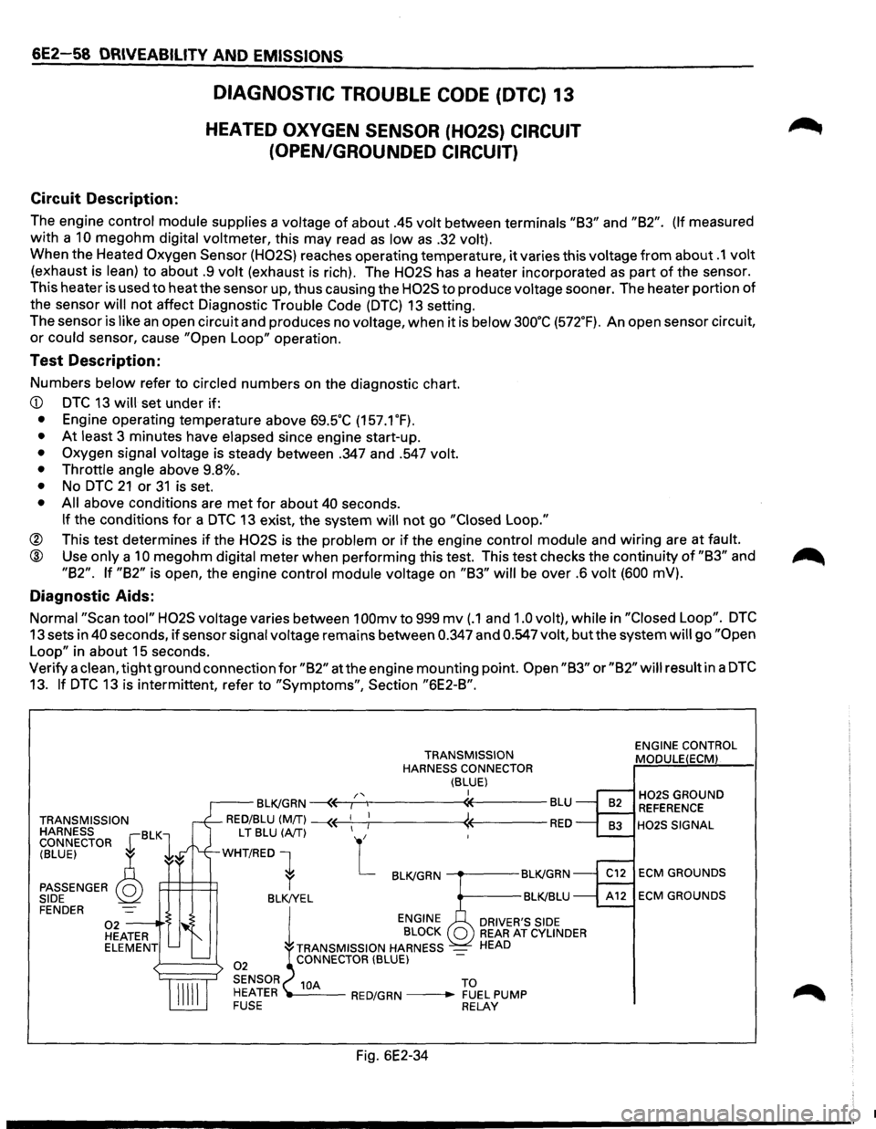
Circuit Description:
DIAGNOSTIC TROUBLE CODE (DTC) 13
HEATED OXYGEN SENSOR (H02S) CIRCUIT
(OPEN/GROUNDED CIRCUIT)
The engine control module supplies a voltage of about .45 volt between terminals "83" and "82". (If measured
with a
10 megohm digital voltmeter, this may read as low as .32 volt).
When the Heated Oxygen Sensor (H02S) reaches operating temperature, it varies this voltage from about .1 volt
(exhaust is lean) to about .9 volt (exhaust is rich). The H02S has a heater incorporated as part of the sensor.
This heater is used to
heatthe sensor up, thus causing the H02S to produce voltage sooner. The heater portion of
the sensor
will not affect Diagnostic Trouble Code (DTC) 13 setting.
The sensor
is like an open circuit and produces no voltage, when it is below 3oo·c (572.F). An open sensor circuit,
or could sensor, cause "Open Loop" operation.
Test Description:
Numbers below refer to circled numbers on the diagnostic chart.
• At least 3 minutes have elapsed since engine start-up.
• Oxygen signal voltage is steady between .347 and .547 volt.
• Throttle angle
above 9.8%.
• No DTC 21 or 31 is set.
• All above conditions are met for about 40 seconds.
If the conditions for a DTC 13 exist, the system will not go "Closed Loop."
® This test determines if the H02S is the problem or if the engine control module and wiring are at fault.
@ Use only a 10 megohm digital meter when performing this test. This test checks the continuity of "83" and
"82". If "82" is open, the engine control module voltage on "83" will be over .6 volt (600 mV).
Diagnostic Aids:
Normal "Scan tool" H02S voltage varies between 1 OOmv to 999 mv (.1 and 1.0 volt), while in "Closed Loop". DTC
13 sets in 40 seconds, if sensor signal voltage remains between 0.347 and 0.547 volt, but the system will go "Open
Loop"
in about 15 seconds.
Verify a
clean, tight ground connection for "82" at the engine mounting point. Open "83" or "82" will result in a DTC
13. If DTC 13 is intermittent, refer to "Symptoms", Section "6E2-8".
TRANSMISSION
HARNESS BLK CONNECTOR r 1
TRANSMISSION
HARNESS CONNECTOR
(BLUE) I /'< r--BLK/GRN ~~,---.,------«----BLU
RED/BLU (MIT) --« ! « RED
(BLUE) ~
PASSENGER Q SIDE
L T BLU (A/T) L
WHT/RED 1
P=H=~ r BLK/GRN ---.---BLK!GRN
BLK!YEL BLK!BLU FENDER
02 -----·'$ HEATER ELEMENT
02
l
ENGINE
BLOCK
TRANSMISSION HARNESS
-CONNECTOR (BLUE)
DRIVER'S SIDE REAR AT CYLINDER HEAD
SENSOR 10A TO
HEATER ---RED/GRN --• FUEL PUMP FUSE RELAY
Fig. 6E2-34
ENGINE CONTROL
MODULE(ECM)
H02S GROUND REFERENCE
H02S SIGNAL
ECM GROUNDS
ECM GROUNDS
•
Page 770 of 1928
6E2-74 DRIVEABILITY AND EMISSIONS
Circuit
Description:
DIAGNOSTIC TROUBLE CODE (DTC) 32
EXHAUST GAS RECIRCULA TION(EGR) CIRCUIT
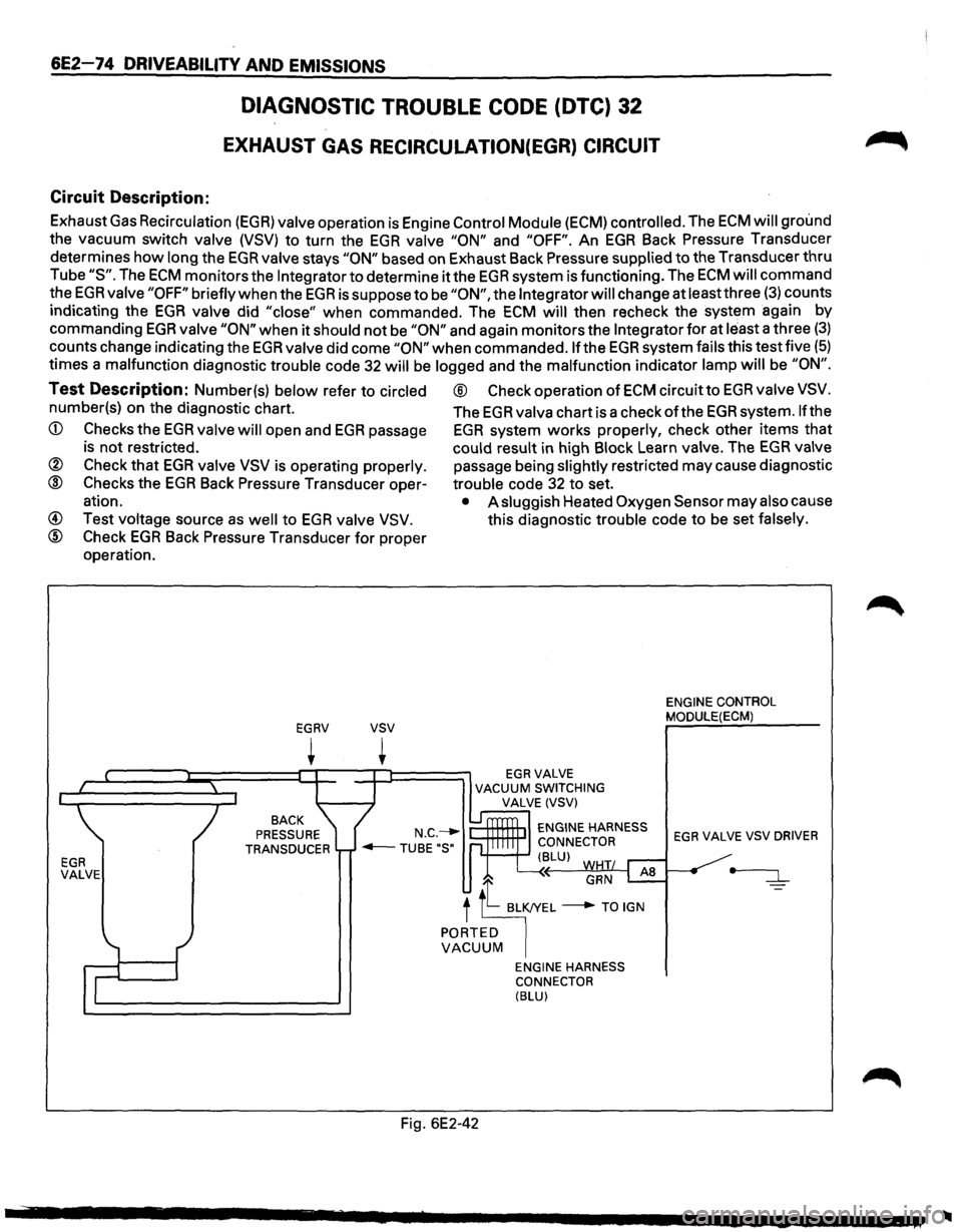
Exhaust Gas Recirculation (EGR) valve operation is Engine Control Module (ECM) controlled. The ECM will ground
the vacuum switch
valve (VSV) to turn the EGR valve "ON" and "OFF". An EGR Back Pressure Transducer
determines how
long the EGR valve stays "ON" based on Exhaust Back Pressure supplied to the Transducer thru
Tube
"S". The ECM monitors the Integrator to determine it the EGR system is functioning. The ECM will command
the
EGR valve "OFF" briefly when the EGR is suppose to be "ON", the Integrator will change at leastthree (3) counts
indicating the
EGR valve did "close" when commanded. The ECM will then recheck the system again by
commanding
EGR valve "ON" when it should not be "ON" and again monitors the Integrator for at least a three (3)
counts change indicating the EGR valve did come "ON" when commanded. If the EGR system fails this test five (5)
times a malfunction diagnostic trouble code 32 will be logged and the malfunction indicator lamp will be "ON".
Test Description: Number(s) below refer to circled ® Check operation of ECM circuit to EGR valve VSV.
number(s} on the diagnostic chart. The EGR valva chart is a check of the EGR system. If the
CD Checks the EGR valve will open and EGR passage EGR system works properly, check other items that
is not restricted. could result in high Block Learn valve. The EGR valve
® Check that EGR valve VSV is operating properly. passage being slightly restricted may cause diagnostic
® Checks the EGR Back Pressure Transducer oper-trouble code 32 to set.
ation.
• A sluggish Heated Oxygen Sensor may also cause
@ Test voltage source as well to EGR valve VSV. this diagnostic trouble code to be set falsely.
@ Check EGR Back Pressure Transducer for proper
operation.
EGR VALVE EGRV
~
BACK
PRESSURE
TRANSDUCER
vsv
~ EGRVALVE VACUUM SWITCHING
VALVE (VSV)
ENGINE HARNESS
CONNECTOR
'+--+-' (BLU) WHT
GRN AS
f fl "'I" ___.. TO IGN PORTED VACUUM
Fig. 6E2-42
ENGINE HARNESS
CONNECTOR
(BLU)
ENGINE CONTROL
MODULE(ECM)
EGR VALVE VSV DRIVER
•
Page 778 of 1928
6E2-82 DRIVEABILITY AND EMISSIONS
Circuit Description:
DIAGNOSTIC TROUBLE CODE (DTC) 43
KNOCK SENSOR (KS) CIRCUIT
(DOHC)
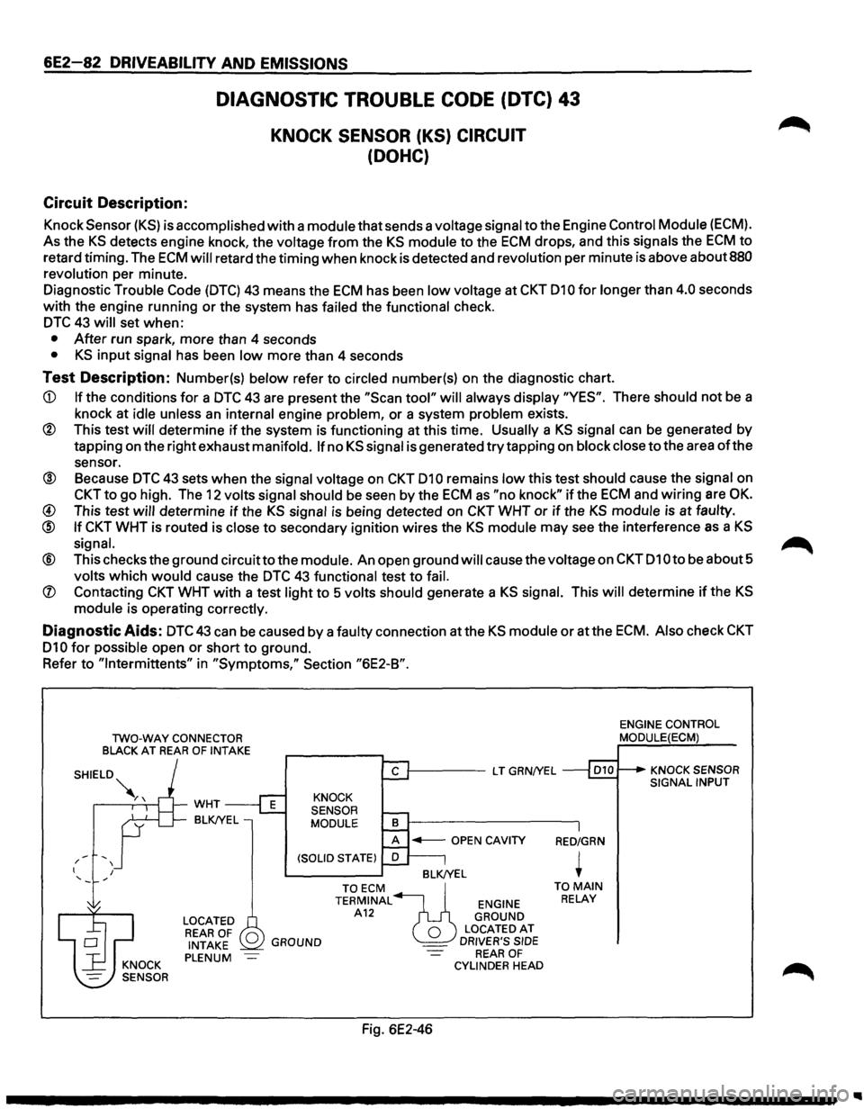
Knock Sensor (KS) is accomplished with a module that sends a voltage signal to the Engine Control Module (ECM).
As the KS detects engine knock, the voltage from the KS module to the ECM drops, and this signals the ECM to
retard timing. The ECM will retard the timing when knock is detected and revolution per minute is above about 880
revolution
per minute.
Diagnostic
Trouble Code (DTC) 43 means the ECM has been low voltage at CKT 010 for longer than 4.0 seconds
with the engine running or the system has
failed the functional check.
DTC 43 will set when:
• After run spark, more than 4 seconds
• KS input signal has been low more than 4 seconds
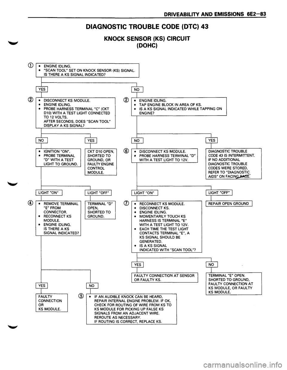
Test Description: Number(s) below refer to circled number(s) on the diagnostic chart.
CD If the conditions for a DTC 43 are present the "Scan tool" will always display "YES". There should not be a
knock at
idle unless an internal engine problem, or a system problem exists.
® This test will determine if the system is functioning at this time. Usually a KS signal can be generated by
tapping on the right exhaust
manifold. If no KS signal is generated try tapping on block close to the area of the
sensor.
® Because DTC 43 sets when the signal voltage on CKT 010 remains low this test should cause the signal on
CKT to go high. The 12 volts signal should be seen by the ECM as "no knock" if the ECM and wiring are OK.
@ This test will determine if the KS signal is being detected on CKT WHT or if the KS module is at faulty.
@ If CKT WHT is routed is close to secondary ignition wires the KS module may see the interference as a KS
signal. ~
® This checks the ground circuitto the module. An open ground will cause the voltage on CKT 010 to be about 5
volts which would cause the DTC 43 functional test to fail.
(J) Contacting CKT WHT with a test light to 5 volts should generate a KS signal. This will determine if the KS
module is operating correctly.
Diagnostic Aids: DTC43 can be caused by a faulty connection atthe KS module or atthe ECM. Also check CKT
010 for possible open or short to ground.
Refer
to "lntermittents" in "Symptoms," Section "6E2-B".
TWO-WAY CONNECTOR
BLACK AT REAR OF INTAKE
-' / I I
WHT
BLK!YEL
LOCATED REAR OF 0 INTAKE PLENUM
1-----L T GRN/YEL
KNOCK
SENSOR
MODULE
BLK/YEL
GROUND
TOECM ~ TERMINAL ENGINE A12 GROUND
0 LOCATEDAT _ DRIVER'S SIDE REAR OF CYLINDER HEAD
Fig. 6E2-46
RED/GRN
+ TO MAIN RELAY
ENGINE CONTROL MODULE(ECM)
KNOCK SENSOR SIGNAL INPUT
Page 779 of 1928
CD
DRIVEABILITV AND EMISSIONS 6E2-83
• ENGINE IDLING.
DIAGNOSTIC TROUBLE CODE (DTC) 43
KNOCK SENSOR (KS) CIRCUIT
(DOHC)
• "SCAN TOOL" SET ON KNOCK SENSOR (KS} SIGNAL. IS THERE A KS SIGNAL INDICATED?
~ $
• DISCONNECT KS MODULE. ® • ENGINE IDLING.
• ENGINE IDLING. • TAP ENGINE BLOCK IN AREA OF KS. • PROBE HARNESS TERMINAL "C" (CKT • IS A KS SIGNAL INDICATED WHILE TAPPING ON
D10} WITH A TEST LIGHT CONNECTED
ENGINE?
TO 12 VOLTS. AFTER SECONDS, DOES "SCAN TOOL"
DISPLAY A KS SIGNAL?
$ ~ ~ ~ • IGNITION "ON". CKT D10 OPEN, @ • DISCONNECT KS MODULE. DIAGNOSTIC
TROUBLE
• PROBE TERMINAL SHORTED TO • PROBE HARNESS TERMINAL "D" CODE 43 IS INTERMITTENT. "D" WITH A TEST
GROUND, OR WITH A TEST LIGHT TO 12V. IF NO ADDITIONAL
LIGHT TO GROUND. FAULTY ENGINE DIAGNOSTIC TROUBLE
CONTROL CODES WERE STORED,
MODULE.
REFER TO "DIA~= AIDS" ON FAGIN .
I I
LIGHT "ON" I LIGHT "OFF" I LIGHT "ON" j LIGHT "OFF" I
I
I
• REMOVE TERMINAL TERMINAL "D" (J) • RECONNECT KS MODULE. REPAIR
OPEN GROUND I "E" FROM
OPEN, • DISCONNECT KS . CONNECTOR.
SHORTED TO • ENGINE IDLING.
• RECONNECT KS GROUND. • MOMENTARILY TOUCH KS MODULE.
HARNESS IS TERMINAL "E" • ENGINE IDLING. WITH A TEST LIGHT TO 12V. IS THERE A KS • EACH TIME THE TEST LIGHT
SIGNAL INDICATED?
CONTACTS TERMINAL "E", A KS SIGNAL SHOULD BE GENERATED. • IS A KS SIGNAL
INDICATED WITH "SCAN TOOL"?
~ $
~
FAULTY CONNECTION AT SENSOR TERMINAL "E" OPEN. OR FAULTY KS. SHORTED
TO GROUND,
~
FAULTY CONNECTION AT KS MODULE, OR FAULTY KS MODULE. FAULTY @ • IF AN AUDIBLE KNOCK CAN BE HEARD, CONNECTION
REPAIR INTERNAL ENGINE PROBLEM. IF OK, OR CHECK FOR ROUTING OF WIRE FROM KS TO KS MODULE. KS MODULE FOR PICKING UP FALSE KS SIGNALS FROM AN ADJACENT WIRE.
REROUTE AS NECESSARY. IF ROUTING IS CORRECT, REPLACE KS.
Page 780 of 1928
6E2-84 DRIVEABILITY AND EMISSIONS
DIAGNOSTIC TROUBLE CODE (DTC) 44
HEATED OXYGEN SENSOR (H02S) CIRCUIT
(LEAN HEATED OXYGEN SENSOR (H02S) SIGNAL INDICATED)
Circuit Description:
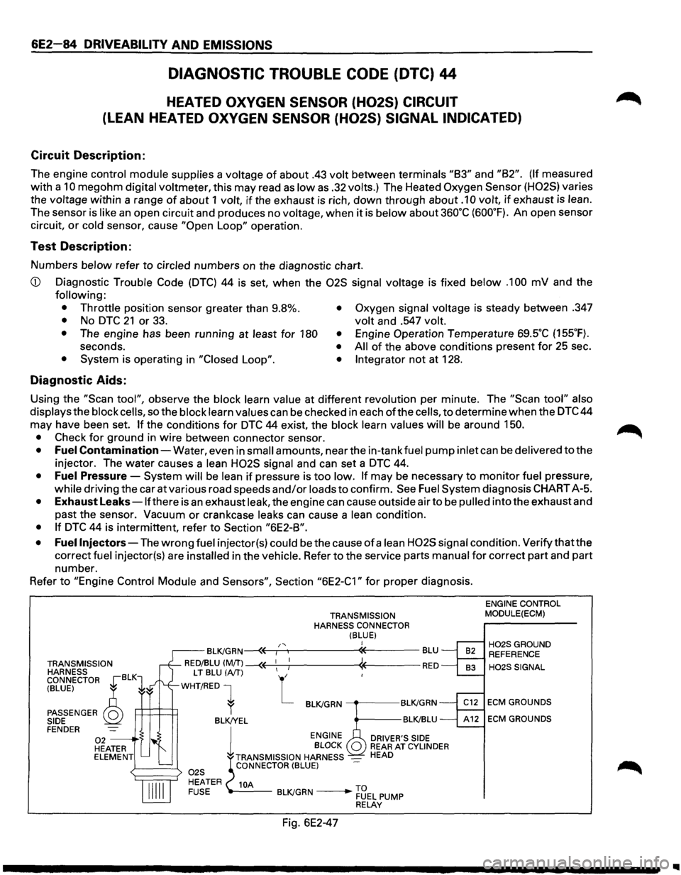
The engine control module supplies a voltage of about .43 volt between terminals "83" and "82". (If measured
with a
10 megohm digital voltmeter, this may read as low as .32 volts.) The Heated Oxygen Sensor (H02S) varies
the
voltage within a range of about 1 volt, if the exhaust is rich, down through about .1 0 volt, if exhaust is lean.
The sensor is like an open circuit and produces no voltage, when it is below about 360°C (600°F). An open sensor
circuit,
or cold sensor, cause "Open Loop" operation.
Test Description:
Numbers below refer to circled numbers on the diagnostic chart.
CD Diagnostic Trouble Code (DTC) 44 is set, when the 02S signal voltage is fixed below .1 00 mV and the
following:
• Throttle
position sensor greater than 9.8%.
• No DTC 21 or 33. • Oxygen signal voltage is steady between .347
volt and .547 volt.
•
The engine has been running at least for 180 •
seconds. • • System is operating in "Closed Loop". •
Engine Operation Temperature 69SC (155°F).
All of the above conditions present for 25 sec .
Integrator not at 128 .
Diagnostic Aids:
Using the "Scan tool", observe the block learn value at different revolution per minute. The "Scan tool" also
displays
the block cells, so the block learn values can be checked in each ofthe cells, to determine when the DTC 44
may have been set.
If the conditions for DTC 44 exist, the block learn values will be around 150.
•
Check for ground in wire between connector sensor.
• Fuel Contamination-Water, even in small amounts, near the in-tank fuel pump inlet can be delivered to the
injector. The water causes a
lean H02S signal and can set a DTC 44.
• Fuel Pressure-System will be lean if pressure is too low. If may be necessary to monitor fuel pressure,
while driving the car at various road speeds and/or loads to confirm. See Fuel System diagnosis CHART A-5.
• Exhaust Leaks -lfthere is an exhaust leak, the engine can cause outside air to be pulled into the exhaust and
past the sensor.
Vacuum or crankcase leaks can cause a lean condition.
• If DTC 44 is intermittent, refer to Section "6E2-8".
• Fuel
Injectors-The wrong fuel injector(s) could be the cause of a lean H02S signal condition. Verify that the
correct
fuel injector(s) are installed in the vehicle. Refer to the service parts manual for correct part and part
number.
Refer
to "Engine Control Module and Sensors", Section "6E2-C1" for proper diagnosis.
TRANSMISSION
HARNESS
CONNECTOR
~BLK1
TRANSMISSION
HARNESS CONNECTOR
(BLUE) I /' BL~GRN~r-~----------~-------BLU
RED/BLU (MfT) --(( 1
1 ; « RED
(BLUE) ~
PASSENGER Q SIDE
LT BLU (A/T) L
WHT/RED 1
P:::l=t=t1 l BL~GRN ----.-----BL~GRN
BLK!YEL BL~BLU FENDER 02 --·S HEATER ELEMENT l
ENGINE
DRIVER'S SIDE BLOCK REAR AT CYLINDER
TRANSMISSION HARNESS _ HEAD CONNECTOR (BLUE)
10A -----BL~GRN ____ .,.... ~3EL PUMP RELAY
Fig. 6E2-47
ENGINE CONTROL
MODULE(ECM)
H02SGROUND REFERENCE
H02SSIGNAL
ECM GROUNDS
ECM GROUNDS
..
Page 782 of 1928
6E2-86 DRIVEABILITY AND EMISSIONS
DIAGNOSTIC TROUBLE CODE (DTC) 45
HEATED OXYGEN SENSOR (H02S) CIRCUIT
(RICH
HEATED OXYGEN SENSOR (H02S) SIGNAL INDICATED)
Circuit Description:
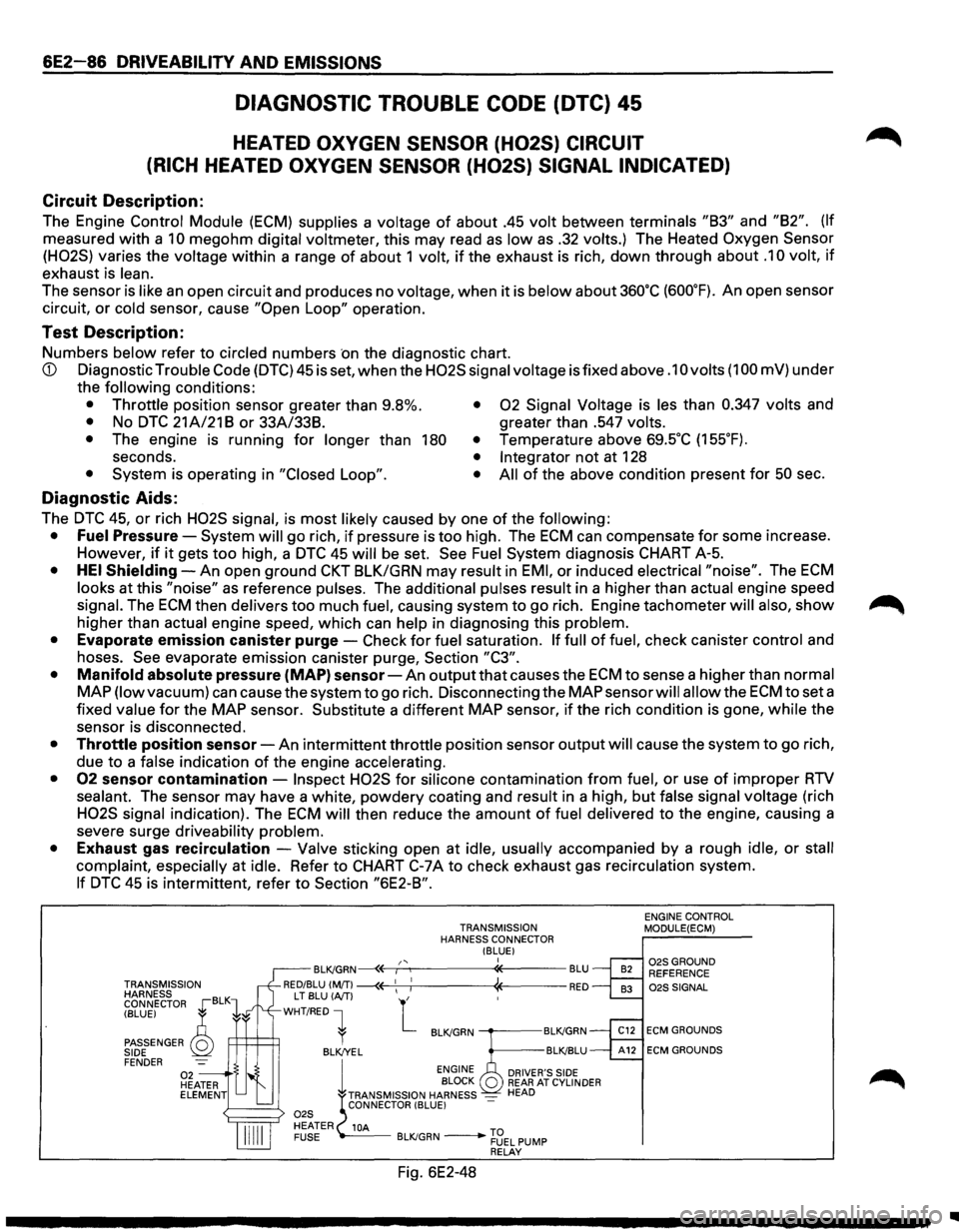
The Engine Control Module (ECM) supplies a voltage of about .45 volt between terminals "83" and "82". (If
measured with a 10 megohm digital voltmeter, this may read as low as .32 volts.) The Heated Oxygen Sensor
(H02S)
varies the voltage within a range of about 1 volt, if the exhaust is rich, down through about .1 0 volt, if
exhaust is lean.
The sensor is like an open circuit and produces no voltage, when it is below about 360"C (600"F). An open sensor
circuit,
or cold sensor, cause "Open Loop" operation.
Test Description:
Numbers below refer to circled numbers ·on the diagnostic chart.
CD Diagnostic Trouble Code (DTC) 45 is set, when the H02S signal voltage is fixed above .1 0 volts (1 00 mV) under
the
following conditions:
• Throttle position sensor greater than 9.8%. • 02 Signal Voltage is les than 0.347 volts and
• No DTC 21 A/21 8 or 33A/338. greater than .547 volts.
•
The engine is running for longer than 180 • Temperature above 69.5"C (155"F).
seconds. • Integrator not at 128
• System is operating in "Closed Loop". • All of the above condition present for 50 sec.
Diagnostic Aids:
The DTC 45, or rich H02S signal, is most likely caused by one of the following:
• Fuel Pressure-System will go rich, if pressure is too high. The ECM can compensate for some increase.
However,
if it gets too high, a DTC 45 will be set. See Fuel System diagnosis CHART A-5.
• HEI Shielding-An open ground CKT BLK/GRN may result in EMI, or induced electrical "noise". The ECM
looks at this "noise" as reference pulses. The additional pulses result in a higher than actual engine speed
signal. The ECM then delivers too much fuel, causing system to go rich. Engine tachometer will also, show ~
higher than actual engine speed, which can help in diagnosing this problem.
• Evaporate emission canister purge-Check for fuel saturation. If full of fuel, check canister control and
hoses.
See evaporate emission canister purge, Section "C3".
• Manifold absolute pressure (MAP) sensor-An output that causes the ECM to sense a higher than normal
MAP (low vacuum) can causethesystemto go rich. Disconnecting the MAP sensor will allow the ECMtoseta
fixed value for the MAP sensor. Substitute a different MAP sensor, if the rich condition is gone, while the
sensor is disconnected.
• Throttle position sensor-An intermittent throttle position sensor output will cause the system to go rich,
due
to a false indication of the engine accelerating.
• 02 sensor contamination -Inspect H02S for silicone contamination from fuel, or use of improper RTV
sealant. The sensor may have a white, powdery coating and result in a high, but false signal voltage (rich
H02S signal indication). The ECM will then reduce the amount of fuel delivered to the engine, causing a
severe surge driveability problem.
• Exhaust gas recirculation -Valve sticking open at idle, usually accompanied by a rough idle, or stall
complaint, especially at idle. Refer to CHART C-7A to check exhaust gas recirculation system.
If DTC 45 is intermittent, refer to Section "6E2-8".
TRANSMISSION
HARNESS
CONNECTOR ,[BLK1
TRANSMISSION
HARNESS CONNECTOR !BLUE I I ,, BLK!GRN~E----r:......,-----"*----BLU
RED/BLU (MfT) ~ 1
1 1 RED
(BLUE) ~
PASSENGER Q SIDE FENDER
L T
BLU (AfT) L WHT/RED 1
R=+=+=:R l BLK!GRN -----BLK!GRN
BLK/YEL BLK!BLU
1
ENGINE
BLOCK Q TRANSMISSION HARNESS -CONNECTOR (BLUE) -
DRIVER'S SIDE REAR AT CYLINDER HEAD
10A BLK/GRN -~~EL PUMP RELAY
Fig. 6E2-48
ENGINE CONTROL MODULE(ECM)
02SGROUND REFERENCE 02S SIGNAL
ECM GROUNDS
ECM GROUNDS
..
Page 787 of 1928
FUEL SYSTEM
• CHECK:
• CHECK:
• CHECK:
• CHECK:
• CHECK:
• CHECK:
Fuel pump relay operation-pump should
turn "ON" for 2 seconds when ignition is
turned
"ON". Use CHART A-5.
Fuel injectors are correct for the vehicle.
Fuel
pressure, use CHART A-7.
Contaminated
fuel.
Engine fuse (visual inspect).
A
faulty in-tank fuel pump check valve will
allow
the fuel in the lines to drain back to
the tank after engine is stopped. To check
for this condition, perform fuel system
diagnosis CHART A-7.
IGNITION SYSTEM
• CHECK: For proper ignition voltage output with
spark tester J26792 or equivalent (ST-
125).
DRIVEABILITY AND EMISSIONS 6E2-91
• CHECK: Spark plugs. Remove spark plugs, check
for wet plugs, cracks, wear, improper
gap, burned electrodes, or heavy
deposits. Repair
or replace as necessary.
• CHECK: Bare or shorted wires.
• CHECK: Loose ignition coil ground.
ADDITIONAL CHECKS
• CHECK: Idle air control operation-use CHART C-
2C.
• CHECK: Basic engine problem. Refer to ENGINE
MECHANICAL DIAGNOSIS (SECTION
6A).
• CHECK: Service Bulletins for calibration updates.
SURGES AND/OR CHUGGLES
Definition: Engine power variation under steady
throttle or cruise. Feels like the car speeds
up and
slows down with no change in the
acceleration pedal.
PRELIMINARY CHECKS
• Perform the careful visual checks as described at
start
of "Symptoms," Section "6E2-B."
•
Be sure driver understands transmission
operation, and air conditioning compressor
operation
as explained in the owner's manual.
SENSORS
• CHECK: Heated oxygen sensor (H02S). The
H02S should respond quickly to different
throttle position, if it does not, check the
H02S for silicon or other contaminations
from fuel, or use of improper RTV sealant.
The sensor may have a white, powdery
coating and result in a high but false
signal voltage
(rich heated H02S signal
indication). The engine control module
will
then reduce the amount of fuel
delivered
to the engine, causing a severe
driveability problem. Also, watch for
green glycol contamination or cracking.
FUEL SYSTEM
• NOTICE: To determine ifthe condition is caused by
a rich
or lean system, the car should be
driven at the speed of the complaint.
Monitoring block learn will help identify a
problem.
Lean -Block learn above 142. Refer to
"Diagnostic Aids" on facing page of
diagnostic trouble code 44.
Rich -L.T. Fuel Trim above 118. Refer to
"Diagnostic Aids" on facing page of
diagnostic trouble code 45.
• CHECK: Fuel pressure while condition exists. Use
CHART A-7.
• CHECK: In-line fuel filter. Replace if dirty or
plugged.
IGNITION SYSTEM
• CHECK: For proper ignition voltage output using
spark tester (ST-125) J26792
or
equivalent .
• CHECK: Spark plugs. Remove spark plugs, check
for wet plugs, cracks, wear, improper
gap, burned electrodes, or heavy
deposits. Repair
or replace as necessary.
Also, check condition of electronic
ignition and spark plug wires.
• CHECK: Ignition timing. Using "Scan tool".
ADDITIONAL CHECKS
• CHECK: Engine control module grounds for being
clean, tight and in their proper location.
• CHECK: Vacuum lines for kinks or leaks.
• CHECK: Exhaust gas recirculation -There should
be no exhaust gas recirculation at idle.
Refer to CHART C-7.
• CHECK: Generator output voltage. Repair if less
than 9 or more than 16 volts.
Page 792 of 1928
6E2-96 DRIVEABILITY AND EMISSIONS
EXCESSIVE EXHAUST EMISSIONS OR ODORS
Definition: Vehicle fails an emission test. Vehicle has
excessive
"rotten egg" smell. Excessive
odors
do not necessarily indicate
excessive emissions.
PRELIMINARY CHECKS
• Perform on-board diagnostic system check.
• IF EMISSION TEST shows excessive CO and
hydrocarbon check items which cause car to run
RICH (Long Term Fuel Trim less than 118), refer to
"Diagnostic Aids" on facing page of diagnostic
trouble code (DTC) 45.
• If EMISSION TEST shows excessive NOx, check
items which cause car
to run lean or too hot.
COOLING SYSTEM
• If the "Scan tool" indicates a very high engine
coolant temperature and the system is running
lean:
CHECK: Engine coolant level
CHECK: Engine thermostat for faulty part
(always open) or for wrong heat range. Refer
to
ENGINE COOLING (SECTION 68).
CHECK: Cooling fan operation.
FUEL SYSTEM
• NOTICE: If the system is running rich (L.T. Fuel
Trim near 118), refer to "Diagnostic Aids"
on facing page
of DTC 45.
-
If the system is running lean (L.T. Fuel
Trim near 142) refer to "Diagnostic
Aids" on facing page of DTC 44.
• CHECK: For properly installed fuel cap.
• CHECK: Fuel pressure. Use CHART A-7.
• CHECK: Canister for fuel loading. Refer to
"Evaporative Emission Control System,"
Section
"6E2-C3."
IGNITION SYSTEM
• CHECK: Ignition timing. Refer to "Vehicle
Emission Control Information" label.
• CHECK: Spark plugs, plug wires, and ignition
components. Refer to
ENGINE
ELECTRICAL (SECTION 6D).
ADDITIONAL CHECKS
• CHECK: For vacuum leaks.
• CHECK: Exhaust gas recirculation valve for not
opening. Use CHART C-7.
• CHECK: For lead contamination of three way
catalytic converter (look for the removal
of fuel filler neck restrictor).
• CHECK: Carbon build-up. Remove carbon with
top engine cleaner. Follow instructions
on can.
• CHECK: PCV valve for being plugged, stuck or
blocked PCV hose or fuel in the
crankcase.
BACKFIRE
Definition: Fuel ignites in intake manifold, or in
exhaust system, making
loud popping
noise.
PRELIMINARY CHECKS
• Perform the careful visual/physical checks as
described at start of "Symptoms," Section "6E2-
B."
IGNITION SYSTEM
• CHECK: Proper ignition coil output voltage with
spark tester J26792 or equivalent (ST-
125).
• CHECK: Spark plugs. Remove spark plugs, check
for
wet plugs, cracks, wear, improper
gap, burned
electrodes, or heavy
deposits. Repair
or replace as necessary.
• CHECK: Spark plug wires for crossfire, also
inspect electronic ignition, spark plug
wires, and proper routing of plug wires.
• CHECK: Ignition timing. Refer to "Vehicle
Emission Control Information" label.
• CHECK: If an intermittent condition exists in the
ignition system, see
"Ignition System/
IGNITION CONTROL," Section "6E2-C4"
or ENGINE ELECTRICAL (SECTION 6D).
ENGINE MECHANICAL
• CHECK: Compression- Look for sticking or leaking
valves.
• CHECK: Valve timing, refer to ENGINE
MECHANICAL DIAGNOSIS (SECTION
6A).
• CHECK: Intake and exhaust manifold passages for
casting
flash.
FUEL SYSTEM
• CHECK: Perform fuel system diagnosis check, see
CHART A-7.