torque ISUZU TROOPER 1995 Workshop Manual
[x] Cancel search | Manufacturer: ISUZU, Model Year: 1995, Model line: TROOPER, Model: ISUZU TROOPER 1995Pages: 1928
Page 1087 of 1928
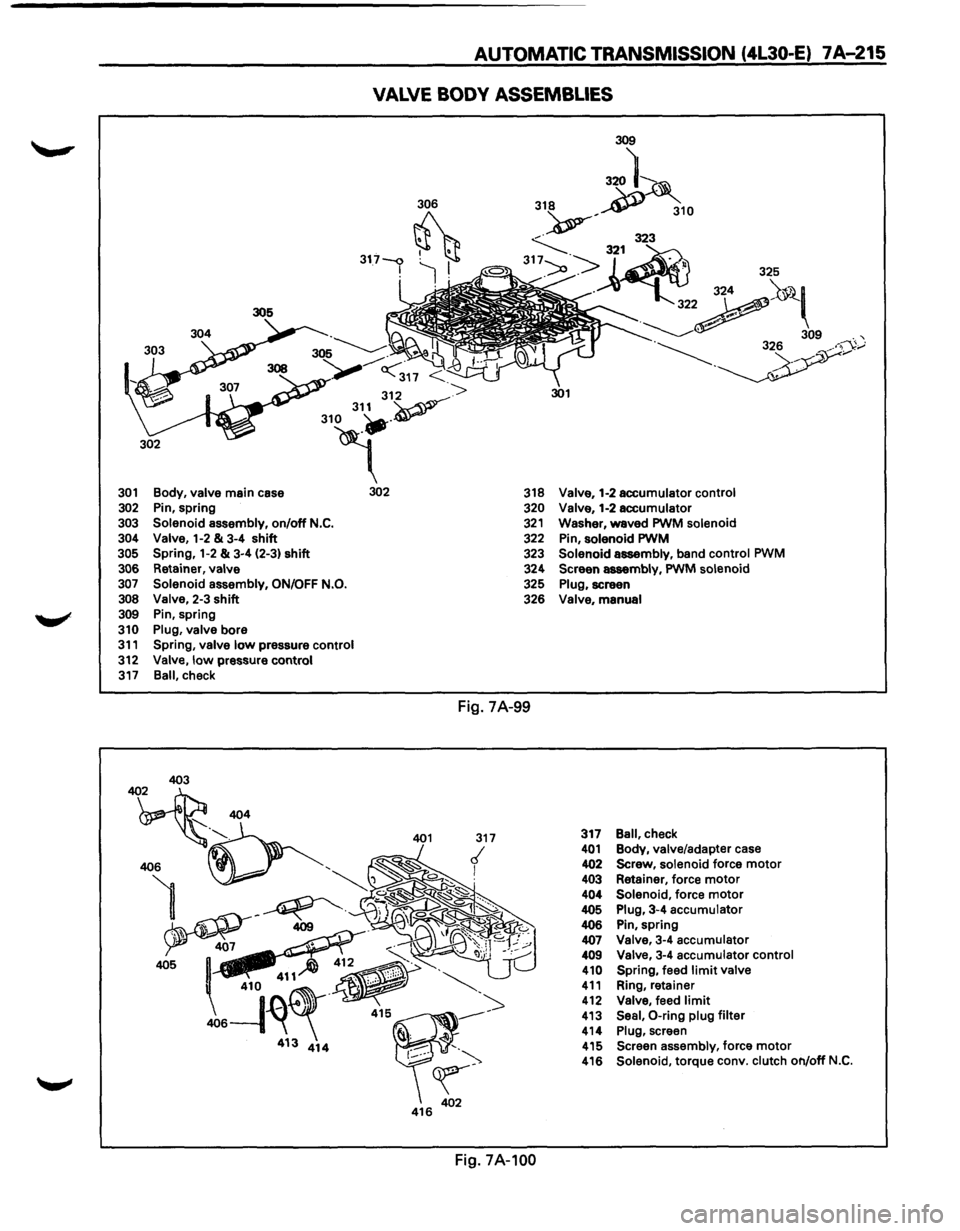
AUTOMATIC TRANSMISSION (4L30-E) 7A-215
VALVE BODY ASSEMBLIES
306
317-<:> . I ~ jl
<317 <
312 ->
310 31~v--
4" 301 Body, valve main case 302
302 Pin, spring
303 Solenoid assembly, on/off N.C. 304 Valve, 1-2 & 3-4 shift 305 Spring, 1-2 & 3-4 (2-3) shift
306 Retainer, valve 307 Solenoid assembly, ON/OFF N.O. 308 Valve, 2-3 shift 309 Pin, spring
310 Plug, valve bore 311 Spring, valve low pressure control
312 Valve, low pressure control 317 Ball, check
318 Valve, 1-2 accumulator control 320 Valve, 1-2 accumulator 321 Washer, waved PWM solenoid 322 Pin, solenoid PWM 323 Solenoid assembly, band control PWM 324 Screen assembly, PWM solenoid 325 Plug, screen 326 Valve, manual
Fig. 7A-99
Fig.
7A-100
317 Ball, check 401 Body, valve/adapter case 402 Screw, solenoid force motor 403 Retainer, force motor 404 Solenoid, force motor 405 Plug, 3-4 accumulator 406 Pin, spring 407 Valve, 3-4 accumulator 409 Valve, 3-4 accumulator control 410 Spring, feed limit valve 411 Ring, retainer 412 Valve, feed limit 413 Seal, 0-ring plug filter 414 Plug, screen 415 Screen assembly, force motor 416 Solenoid, torque conv. clutch on/off N.C.
Page 1091 of 1928
MANUAL TRANSMISSION 78-1
SECTION 78
MANUAL TRANSMISSION
w CAUTION
When fasteners are removed, always reinstall them at the same location from which they were removed. If a
fastener needs
to be replaced, use the correct part number fastener for that application. If the correct part
number fastener is not available, a fastener of equal size and strength (or stronger) may be used. Fasteners
that are not reused, and those requiring thread locking compound, will be called out. The correct torque
values must be used when installing fasteners that require torque. If the above conditions are not followed,
parts or system damage could result.
CONTENTS
General Description . . . . . . . . . . . . . . . . . . . . . 78-1
Construction . . . . . . . . . . . . . . . . . . . . . . . . . 78-2
Diagnosis . . . . . . . . . . . . . . . . . . . . . . . . . . . . . . 78-3
On-Vehicle Service ..................... 78-4
Transmission . . . . . . . . . . . . . . . . . . . . . . . . 78-4
Gear Control Box Assembly . . . . . . . . . . . 78-10
Unit Repair ........................... 78-12
Transmission Case And Transfer
Case .............................. 78-12
Intermediate Plate With Gear Assembly
Detent, Shift Arm, And Interlock Pin ... 78-18
Reverse Gear
And 5th Gear ............ 78-22
Top Gear Shaft, Main Gear Shaft
And Counter Gear Shaft .............. 78-29
Main Data And Specifications ............ 78-39
General Specifications ................ 78-39
Torque Specifications ................ 78-40
Special
Tools .......................... 78-43
GENERAL DESCRIPTION
The MUA5C is a constant mesh transmission,
synchronized in
all speeds. The transmission is
designed
for ease of shifting and the quietest possible
operation.
Principle parts of the transmission are the integral
clutch
housing, intermediate plate, the transfer case,
the rear cover, and the gears.
The transmission
control box and transfer control box
are
built into the transfer case.
Page 1098 of 1928
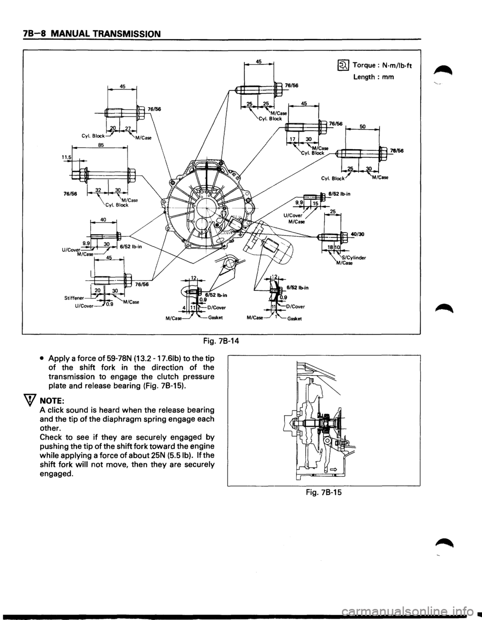
78-8 MANUAL TRANSMISSION
45
Fig. 78-14
• Apply a force of 59-78N (13.2 -17.61b) to the tip
of the shift fork in the direction of the
transmission
to engage the clutch pressure
plate and release bearing (Fig. 78-15).
W NOTE:
A click sound is heard when the release bearing
and the tip
of the diaphragm spring engage each
other.
Check
to see if they are securely engaged by
pushing the tip of the shift fork toward the engine
while applying a force
of about 25N (5.5 I b). If the
shift fork
will not move, then they are securely
engaged.
45 ~ Torque : N·m/lb·ft
Length: mm
Fig. 78-15
..
Page 1099 of 1928
12. Flywheel under cover bolts
• Install
three flywheel under cover bolts.
11. Gear control lever
• Install
the transmission control lever and
transfer
control lever.
• Install
the grommet assembly.
• Install
the front console assembly.
• Install
the gear control lever knob.
• Support the transfer case with a jack and then
remove the transmission jack
from
transmission side.
10. Front propeller shaft
• Install the front propeller shaft.
~~~ Torque N·m (lb·ft) 63 (46)
9. Front crossmember
• Install the front crossmember.
~~~ Torque N·m (lb·ft) 78 (58)
8. Engine rear mount
• Install the engine rear mount.
~~~ Torque N·m (lb·ft) 41 (30)
7. 3rd crossmember
• Install the 3rd crossmember.
1~1 Torque N-m (lb·ft) 50 (37)
6. Engine rear mount nuts
~~~ Torque N-m (lb·ft) 50 (37)
• Remove the transmission jack.
5. Transmission harness connectors
• Install bracket and two transmission harness
clamps to the transmission case (Fig. 78-15a).
• Connect the speed sensor harness connector.
• Connect the reverse lamp switch, 4WD
indicator
switch, 1-2 and 3-4 indicator switch
harness connectors.
Fig. 78-15a
MANUAL TRANSMISSION 78-9
4. Rear propeller shaft
• Install the rear propeller shaft.
I~I __ T_o_rq~u_e __ N_·m~(_lb_·ft~)~ _____ 6_3~(_46~) ____ _
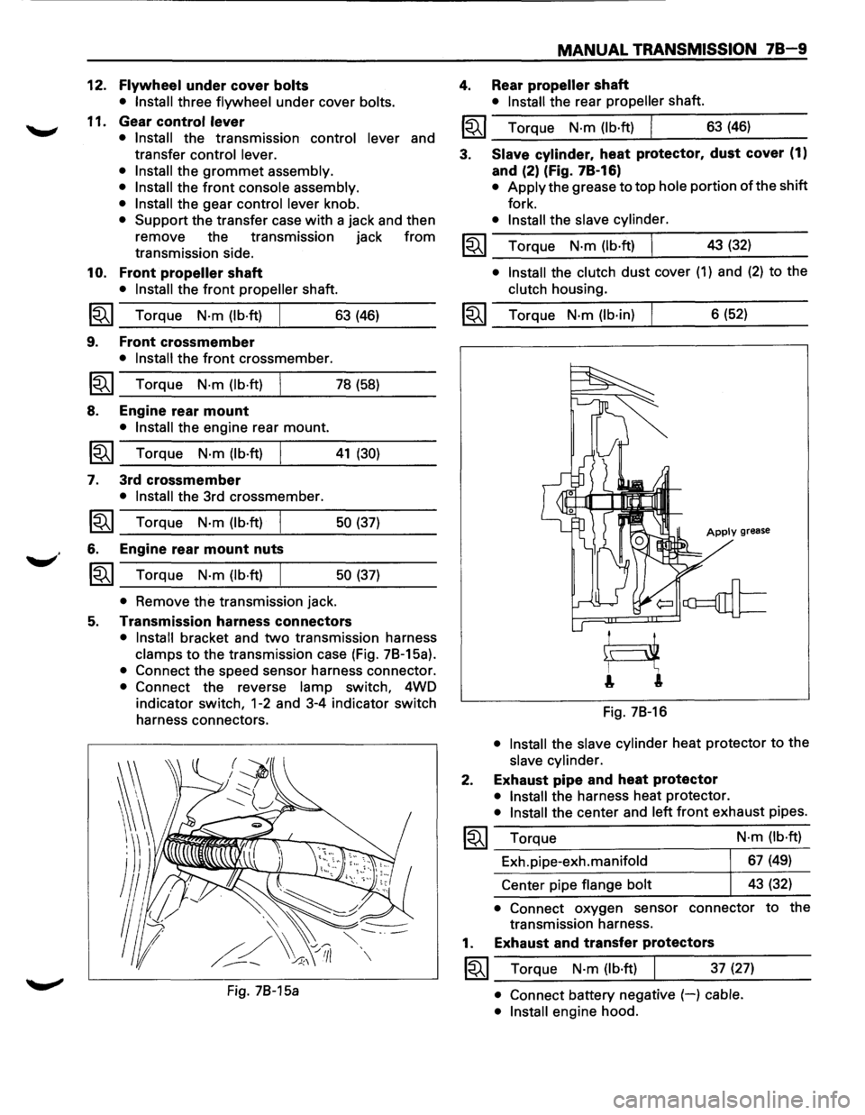
3. Slave cylinder. heat protector. dust cover (1)
and (2) (Fig. 78-16)
• Apply the grease to top hole portion of the shift
fork.
• Install the slave cylinder.
~~~ Torque N·m (lb·ft) I 43 (32) _..:....__~----
• Install the clutch dust cover (1) and (2) to the
clutch housing.
~~~ Torque N·m (lb·in) 6 (52)
Apply grease
Fig. 78-16
• Install the slave cylinder heat protector to the
slave cylinder.
2. Exhaust pipe and heat protector
• Install the harness heat protector.
• Install the center and left front exhaust pipes.
~~~ Torque
Exh.pipe-exh.manifold
Center pipe
flange bolt N·m
(lb·ft)
67 (49)
43 (32)
• Connect oxygen sensor connector to the
transmission harness.
1. Exhaust and transfer protectors
~~~ Torque N·m (lb·ft) 37 (27)
• Connect battery negative (-) cable.
• Install
engine hood.
Page 1100 of 1928
78-10 MANUAL TRANSMISSION
GEAR CONTROL BOX ASSEMBLY
l••l REMOVAL
Preparation:
• Disconnect battery negative (-) cable.
1. Knob
• Remove knobs of the transmission control
lever
and transfer control lever.
2. Front console assembly
• Remove front console assembly.
•
Disconnect harness connector.
• Remove rear heater duct.
3. Grommet assembly
• Remove grommet assembly.
4. Transmission control lever and transfer control
lever
• Remove transmission control lever and
transfer
control lever.
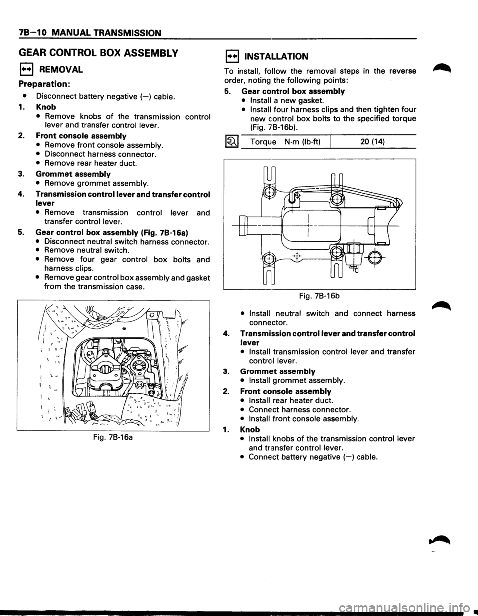
5. Gear control box assembly (Fig. 7B-16a)
• Disconnect neutral switch harness connector.
• Remove neutral switch.
• Remove four gear control box bolts and
harness
clips.
•
Remove gear control box assembly and gasket
from the transmission case.
Fig. 7B-16a
l••l INSTALLATION
To install, follow the removal steps in the reverse
order, noting the
following points:
5. Gear control box assembly
• Install a new gasket.
• Install four harness clips and then tighten four
new control box bolts to the specified torque
(Fig. 7B-16b).
1~1 Torque N·m (lb·ft) 20 (14)
Fig. 7B-16b
• Install neutral switch and connect harness
connector.
4.
Transmission control lever and transfer control
lever
• Install transmission control lever and transfer
control lever.
3. Grommet assembly
• Install grommet assembly.
2. Front console assembly
• Install rear heater duct.
• Conne,ct harness connector.
• Install front console assembly.
1. Knob
• Install knobs of the transmission control lever
and transfer control lever.
• Conne·ct
battery negative (-) cable.
•
Page 1104 of 1928
78-14 MANUAL TRANSMISSION
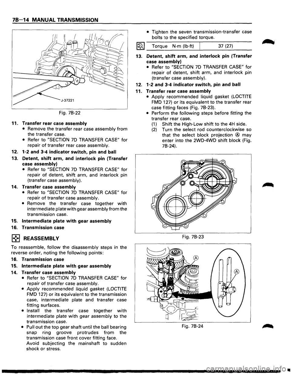
Fig. 78-22
11. Transfer rear case assembly
• Remove the transfer rear case assembly from
the transfer case.
• Refer to "SECTION 7D TRANSFER CASE" for
repair
of transfer rear case assembly.
12. 1-2 and 3-4 indicator switch, pin and ball
13. Detent, shift arm, and interlock pin (Transfer
case
assembly)
• Refer to "SECTION 7D TRANSFER CASE" for
repair of detent, shift arm, and interlock pin
(transfer case assembly).
14. Transfer case assembly
• Refer to "SECTION 7D TRANSFER CASE" for
repair
of transfer case assembly.
• Remove the transfer case together with
intermediate plate with gear assembly from the
transmission case.
15. Intermediate plate with gear assembly
16. Transmission case
l•!•l REASSEMBLY
To reassemble, follow the disassembly steps in the
reverse order, noting the following points:
16. Transmission case
15.
Intermediate plate with gear assembly
14. Transfer case assembly
• Refer to "SECTION 7D TRANSFER CASE" for
repair
of transfer case assembly.
• Apply recommended liquid gasket (LOCTITE
FMD 127) or its equivalent to the transmission
case, intermediate plate and transfer case
fitting surfaces.
• Install the transfer case together with
intermediate plate with gear assembly to the
transmission case.
• Pull out the top gear shaft until the ball bearing
snap ring groove protrudes
from the
transmission case
front cover fitting face.
Avoid subjecting the mainshaft
to sudden
shock
or stress.
• Tightem the seven transmission-transfer case
bolts
ito the specified torque.
I~I __ T_o_rq~u __ e __ N_·_m_(~lb_·f~t)~ ______ 3_7_(2_7~) ____ _
13. Detent, shift arm, and interlock pin (Transfer
case
assembly)
• Refer to "SECTION 7D TRANSFER CASE" for
repair of detent, shift arm, and interlock pin
(transfer case assembly).
12. 1-2 and 3-4 indicator switch, pin and ball
11. Transfe1· rear case assembly
• Apply recommended liquid gasket (LOCTITE
FMD 127) or its equivalent to the transfer rear
case fitting faces (Fig. 78-23).
• Perform the following steps before fitting the
transf13r rear case.
(1) Shift the High-Low shift to the 4H side.
(2) Turn the select rod counterclockwise so
that the select block projection ® may
enter into the 2WD-4WD shift block (Fig.
78-24).
Fig. 78-23
Fig. 78-24
•
Page 1105 of 1928
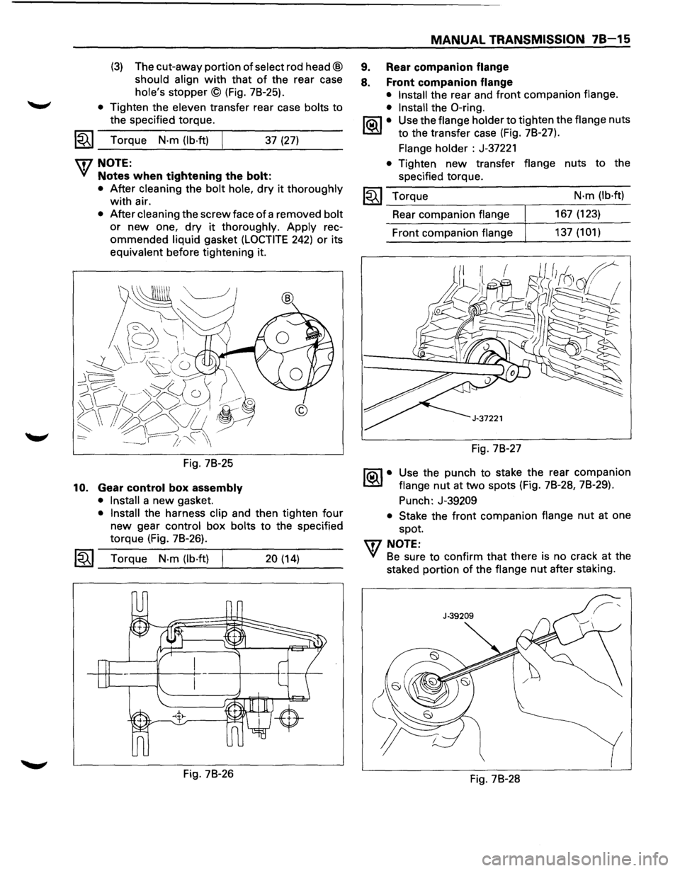
(3) The cut-away portion of select rod head@
should
align with that of the rear case
hole's
stopper© (Fig. 78-25).
• Tighten the eleven transfer rear case bolts to
the specified torque.
1~1 Torque N·m (lb·ft) j 37 (27)
U7NOTE:
'({ Notes when tightening the bolt:
10.
• After cleaning the bolt hole, dry it thoroughly
with air.
• After cleaning the screw face of a removed bolt
or new one, dry it thoroughly. Apply rec
ommended liquid gasket (LOCTITE 242) or its
equivalent before tightening it.
Fig.
78-25
Gear control box assembly
• Install a new gasket.
• Install the harness clip and then tighten four
new gear control
box bolts to the specified
torque (Fig.
78-26).
I~I_T_o_rq_u_e_N_·m_(lb_·_ft)____.l ___ 20_(_1_4) __ _
Fig. 78-26
MANUAL TRANSMISSION 78-15
9. Rear companion flange
8. Front companion flange
• Install the rear and front companion flange.
• Install the 0-ring.
IQil • Use the flange holder to tighten the flange nuts
l..::rJ to the transfer case (Fig. 78-27).
Flange holder : J-37221
• Tighten new transfer flange nuts to the
specified torque.
I~I_T_o_r-..:.q_ue ______ -. ___ N_·_m_(lb_·_ft_)
Rear companion flange 167 (123)
Front companion flange 137 (1 01)
Fig. 78-27
1®.1• Use the punch to stake the rear companion
flange
nut at two spots (Fig. 78-28, 78-29).
Punch: J-39209
• Stake the front companion flange nut at one
spot.
U7 NOTE:
'({ Be sure to confirm that there is no crack at the
staked portion
of the flange nut after staking.
Fig.
78-28
Page 1106 of 1928
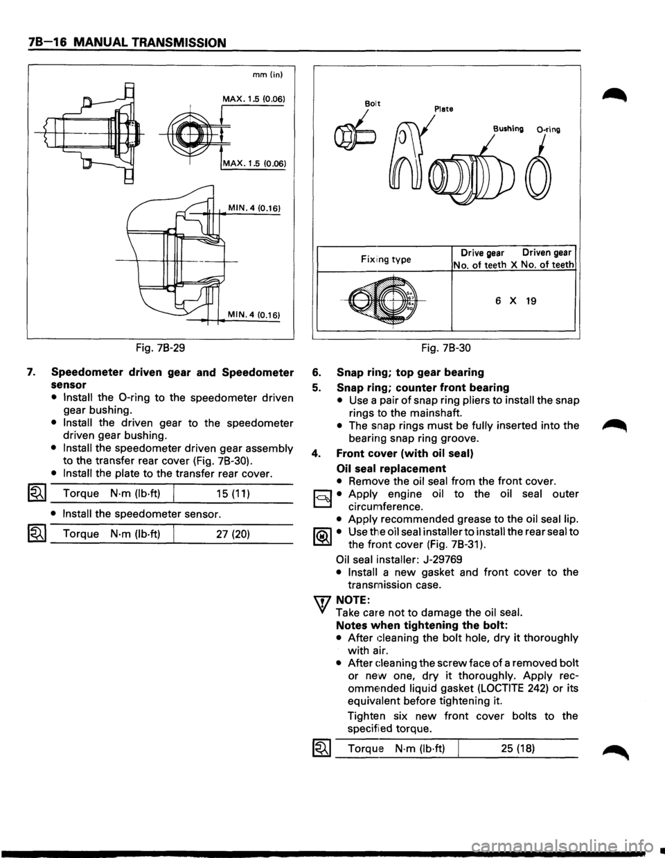
78-16 MANUAL TRANSMISSION
7.
mm{in)
MAX. 1.5 (0.06)
MAX. 1.5 10.06)
MIN. 4 (0.16)
MIN. 4 (0.16)
Fig. 78-29
Speedometer driven gear and Speedometer
sensor
• Install the 0-ring to the speedometer driven
gear bushing.
• Install the driven gear to the speedometer
driven gear bushing.
• Install the speedometer driven gear assembly
to the transfer rear cover (Fig. 78-30).
• Install the plate to the transfer rear cover.
l"i't I Torque N·m (lb·ft) ~ _...:.____---~... ___ _ 15 (11)
• Install the speedometer sensor.
I~I_T_o_rq...;_u_e_N_·_m_(_lb_·ft_l----~. ___ 2_7_(2_0_) __ _
Plate Bolt
~
Fix1ing type Drive gear Driven gear
No. of teeth
X No. of teeth
6 X 19
Fig. 78-30
6. Snap ring; top gear bearing
5. Snap ring; counter front bearing
• Use a pair of snap ring pliers to install the snap
rings to the mainshaft.
• The snap rings must be fully inserted into the
bearing snap ring groove.
4. Front cover (with oil seal)
Oil seal
replacement
• Remove the oil seal from the front cover.
c:::;J • Apply engine oil to the oil seal outer
D circumference.
• Apply recommended grease to the oil seal lip.
1®.1• Use the oil seal installer to install the rear seal to
the
front cover (Fig. 78-31 ).
Oil seal installer: J-29769
• Install a new gasket and front cover to the
transmission case.
'\f7 NOTE:
"+({ Take care not to damage the oil seal.
Notes when tightening the bolt:
• After Gleaning the bolt hole, dry it thoroughly
with air.
• After Gleaning the screw face of a removed bolt
or new one, dry it thoroughly. Apply rec
omme~nded liquid gasket (LOCTITE 242) or its
equivalent before tightening it.
Tighten six
new front cover bolts to the
specified torque.
1~1 Torque N·m (lb·ft) 25 (18)
..
Page 1107 of 1928
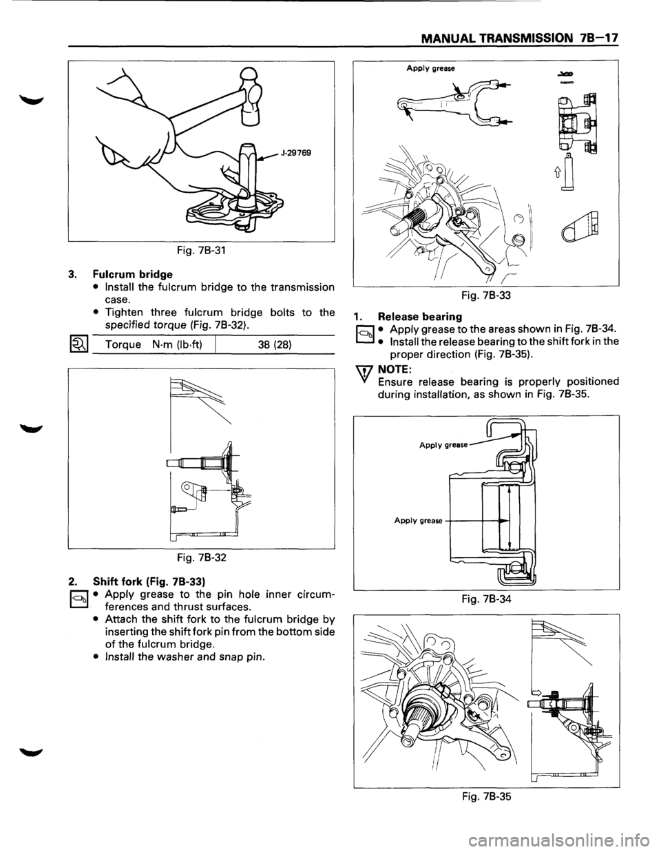
Fig. 78-31
3. Fulcrum bridge
• Install the fulcrum bridge to the transmission
case.
• Tighten three fulcrum bridge bolts to the
specified torque (Fig. 78-32).
~~~ Torque N·m (lb·ft) J 38 (28)
Fig. 78-32
2. Shift fork (Fig. 78-33)
c:::;:]. • Apply grease to the pin hole inner circum
D ferences and thrust surfaces.
• Attach the shift fork to the fulcrum bridge by
inserting the shift fork pin
from the bottom side
of the fulcrum bridge.
• Install the washer and snap pin.
MANUAL TRANSMISSION 78-17
Apply grease
Fig. 78-33
1. Release bearing
c:::;:] • Apply grease to the areas shown in Fig. 78-34.
D • Install the release bearing to the shift fork in the
proper direction (Fig. 78-35).
\f7 NOTE:
'V Ensure release bearing is properly positioned
during
installation, as shown in Fig. 78-35.
Apply grease
Apply grease +---+--11~
Fig. 78-34
Fig. 78-35
Page 1111 of 1928
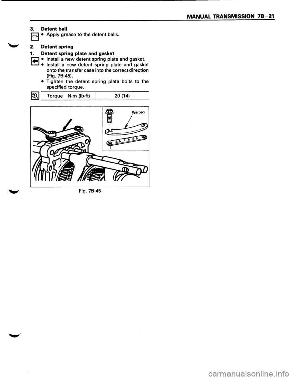
3. Detent ball
E§3 • Apply grease to the detent balls.
2. Detent spring
1. Detent spring
plate and gasket
r=l • Install a new detent spring plate and gasket.
t=.l • Install a new detent spring plate and gasket
onto the transfer case into the correct direction
(Fig. 78-45).
• Tighten the detent spring plate bolts to the
specified torque.
1~1 Torque N·m (lb·ft) I 20 (14)
Fig. 78-45
MANUAL TRANSMISSION 78-21