torque ISUZU TROOPER 1995 Workshop Manual
[x] Cancel search | Manufacturer: ISUZU, Model Year: 1995, Model line: TROOPER, Model: ISUZU TROOPER 1995Pages: 1928
Page 1115 of 1928
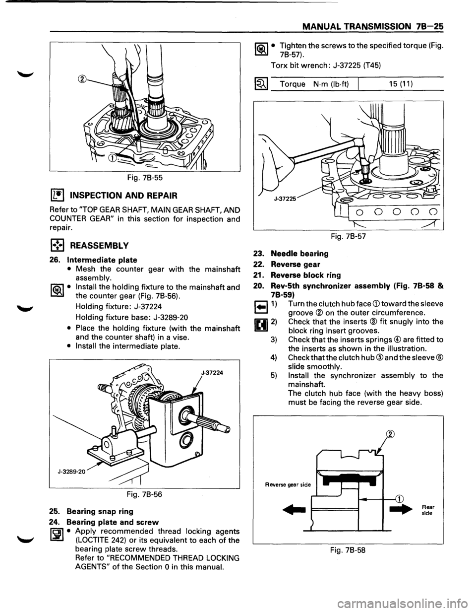
Fig. 78-55
IL•I INSPECTION AND REPAIR
Refer to "TOP GEAR SHAFT, MAIN GEAR SHAFT, AND
COUNTER GEAR" in this section for inspection and
repair.
l•!•l REASSEMBLY
26. Intermediate plate
• Mesh the counter gear with the mainshaft
assembly.
1®.1• Install the holding fixture to the mainshaft and
the counter gear (Fig. 78-56).
Holding fixture: J-37224
Holding fixture base:
J-3289-20
• Place
the holding fixture (with the mainshaft
and the counter shaft) in a vise.
• Install the intermediate plate.
Fig. 78-56
25. Bearing snap ring
24. Bearing
plate and screw
rci1 • Apply recommended thread locking agents
l.:i!.l (LOCTITE 242) or its equivalent to each of the
bearing
plate screw threads.
Refer to
"RECOMMENDED THREAD LOCKING
AGENTS"
of the Section 0 in this manual.
MANUAL TRANSMISSION 78-25
1®.1• Tighten the screws to the specified torque (Fig.
78-57).
Torx bit wrench: J-37225 (T45)
1~1 Torque N·m (lb·ft) I
23. Needle bearing
22. Reverse gear
Fig. 78-57
21. Reverse block ring
15 (11)
20. Rev-5th synchronizer assembly (Fig. 7B·58 &
7B·59)
r=l1) Turn the clutch hub face CD toward the sleeve
~ groove ® on the outer circumference.
0 2) Check that the inserts ® fit snugly into the
1!!.!1 block ring insert grooves.
3) Check that the inserts springs@ are fitted to
the inserts
as shown in the illustration.
4) Check thatthe clutch hub@ and the sleeve®
slide smoothly.
5) Install the synchronizer assembly to the
mainshaft.
The clutch hub face (with the heavy boss)
must be facing the reverse gear side.
Reverse gear side
... F====I
Fig. 78-58
Rear
side
Page 1116 of 1928
78-26 MANUAL TRANSMISSION
Fig. 78-59
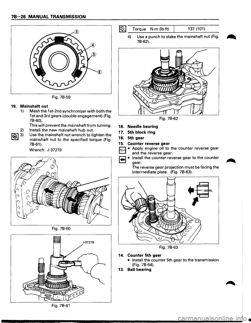
19. Mainshaft nut
1) Mesh the 1st-2nd synchronizer with both the
1st and 3rd gears
(double engagement) (Fig.
78-60).
2)
~3)
This will prevent the mainshaft from turning.
Install the new mainshaft hub nut.
Use the mainshaft
nut wrench to tighten the
mainshaft
nut to the specified torque (Fig.
78-61).
Wrench: J-37219
Fig. 78-60
Fig. 78-61
1~1 Torque N·m (lb·ft) 137 (101)
4) Use a punch to stake the mainshaft nut (Fig. ~
78-62).
18. Needle bearing
17. 5th
block ring
16. 5th gear
Fig. 78-62
15. Counter reverse gear
Cl • Apply engine oil to the counter reverse gear
L.::::::.l and the reverse gear.
8 • Install the counter reverse gear to the counter
gear.
The reverse gear projection
must be facing the
intermediate
plate. (Fig. 78-63).
Fig. 78-63
14. Counte1· 5th gear
• Install the counter 5th gear to the transmission
(Fig. 78-64).
13. Ball bearing
•
Page 1130 of 1928
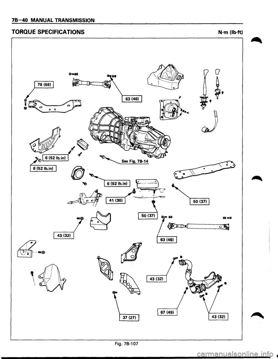
JB 40 MANUAL TRANSMISSION
TORQUE SPECIFICATIONS
~ ~6314611
4
\·
~
[ 67 (49)
Fig. 78-107
N·m (lb·ft)
0. '
•
Page 1131 of 1928
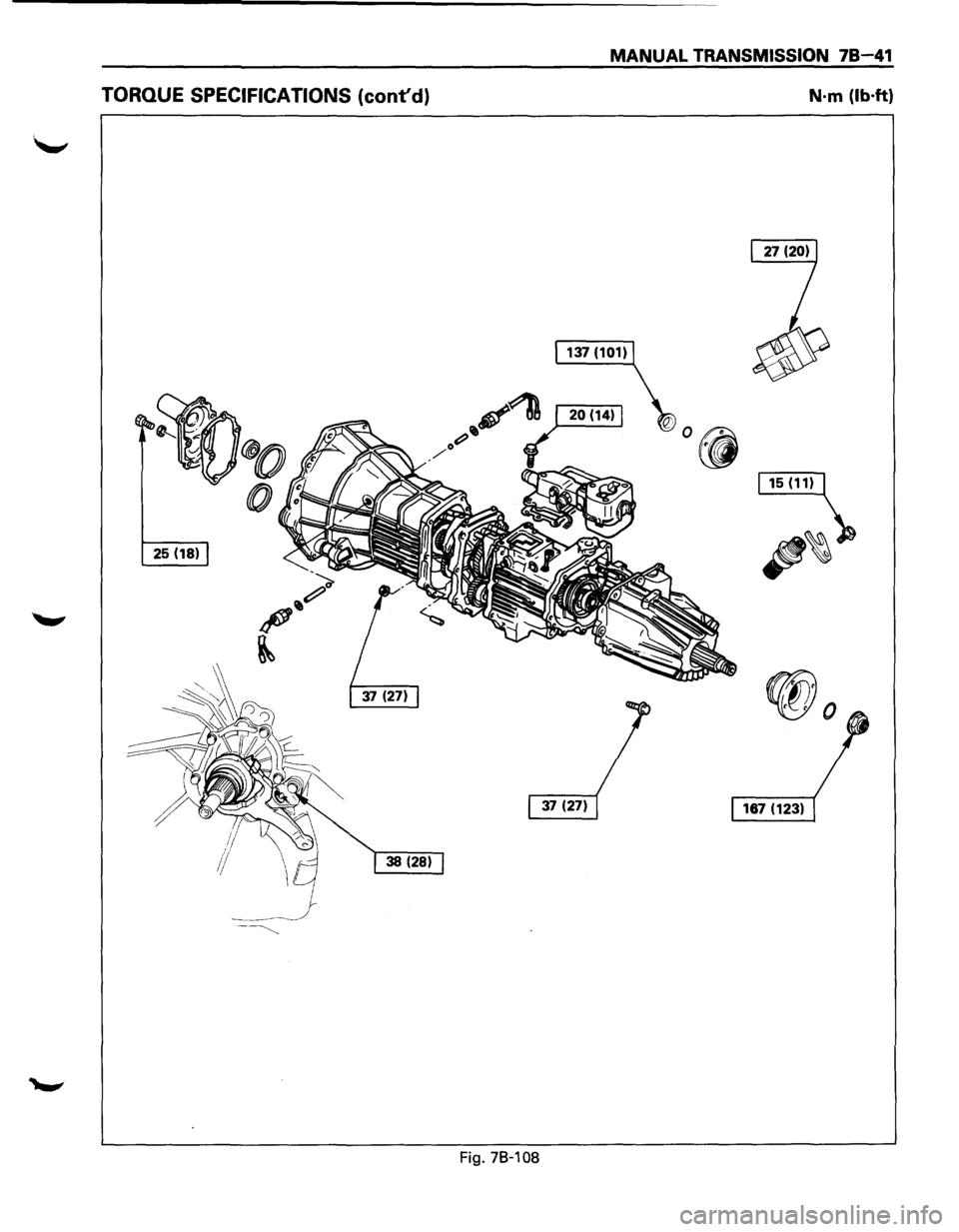
MANUAL TRANSMISSION 78-41
TORQUE SPECIFICATIONS (cont'd) N·m (lb·ft)
25 (18)
Fig. 78-108
Page 1132 of 1928
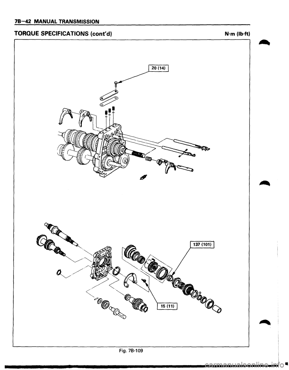
78-42 MANUAL TRANSMISSION
TORQUE SPECIFICATIONS (cont'd) N·m (lb·ft)
20(1~
Fig. 78~109
•
Page 1135 of 1928
CLUTCH 7C-1
SECTION 7C
CLUTCH
W CAUTION:
• When fasteners are removed, always reinstall them at the same location from which they were removed. If a
fastener needs to be
replaced, use the correct part number fastener for that application. If the correct part
number fastener is
not available, a fastener of equal size and strength (or stronger) may be used. Fasteners
that are not reused, and those requiring thread locking compound, will be called out. The correct torque
values must be used when installing fasteners that require torque. If the above conditions are not followed,
parts or system damage could result.
CONTENTS
General Description .................. 7C-2
Clutch ............................ 7C-2
Master
Cylinder ................... 7C- 3
Damper
Cylinder ................... 7C- 3
Slave Cylinder ..................... 7C-3
Pressure
Plate Assembly ........... 7C-4
Driven
Plate Assembly ............. 7C-4
Diagnosis
............................ 7C- 5
On-Vehicle Service ................... 7C-6
Clutch Assembly . .
. . . . . . . . . . . . . . . .
7C-6
Clutch Control . .
. . . . . . . . . . . . . . . . . .
7C-13
Master
Cylinder . .
. . . . . . . . . . . . . . . . .
7C-17
Slave Cylinder . .
. . . . . . . . . . . . . . . . . .
7C-18
Damper
Cylinder . .
. . . . . . . . . . . . . . . .
7C-20
Main
Data And Specifications . .
. . . . . .
7C-21
General Specifications
. . . . . . . . . . . . . 7C-21
Torque Specifications ............. 7C-22
Special Tools ........................ 7C-24
Page 1145 of 1928
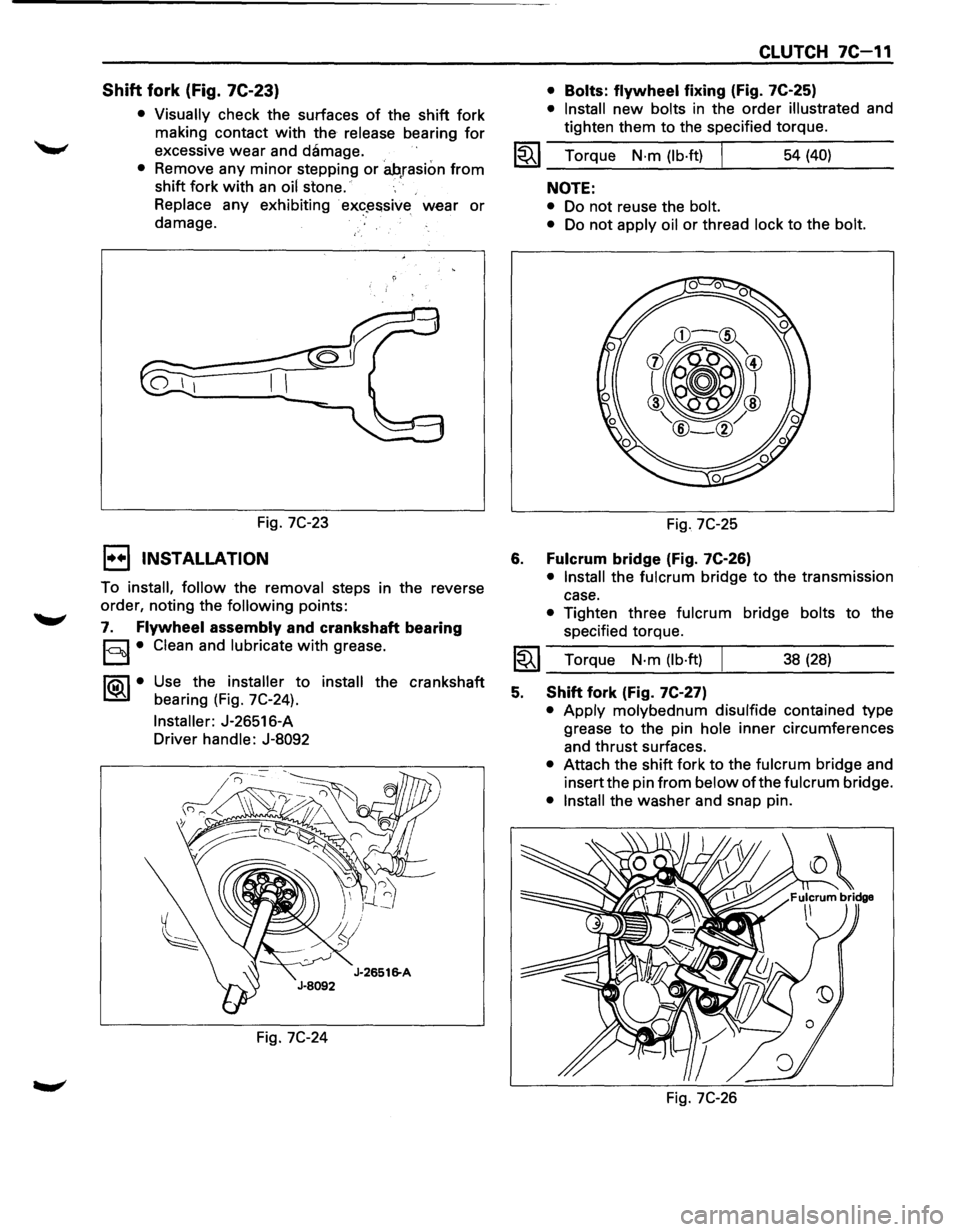
Shift fork (Fig. 7C-23)
• Visually check the surfaces of the shift fork
making contact
with the release bearing for
excessive wear and damage.
• Remove any minor stepping or ah,rasion from
shift fork with an oil stone.
Replace any exhibiting
· ex«?~ssive wear or
damage.
Fig.
7C-23
1••1 INSTALLATION
To install, follow the removal steps in the reverse
order, noting the
following points:
7. Flywheel assembly and crankshaft bearing
§I• Clean and lubricate with grease.
1®..1• Use the installer to install the crankshaft
bearing (Fig. 7C-24).
Installer: J-26516-A
Driver handle: J-8092
Fig.
7C-24
CLUTCH 7C-11
• Bolts: flywheel fixing (Fig. 7C-25)
• Install new bolts in the order illustrated and
tighten them to the specified torque.
1~1 Torque N·m (lb·ft) I 54 (40)
6.
NOTE:
• Do not reuse the bolt.
•
Do not apply oil or thread lock to the bolt.
Fig. 7C-25
Fulcrum bridge (Fig. 7C-26)
• Install the fulcrum bridge to the transmission
case.
• Tighten three fulcrum bridge bolts to the
specified torque.
I~I __ T_o_rq~u_e __ N_·_m~(_lb_·ft_l~ _____ 3_8_(_28_) ____ _
5. Shift fork (Fig. 7C-27)
• Apply molybednum disulfide contained type
grease
to the pin hole inner circumferences
and thrust surfaces.
• Attach the shift fork to the fulcrum bridge and
insert the pin
from below of the fulcrum bridge.
• Install the washer and snap pin.
Fig.
7C-26
Page 1146 of 1928
7C-12 CLUTCH
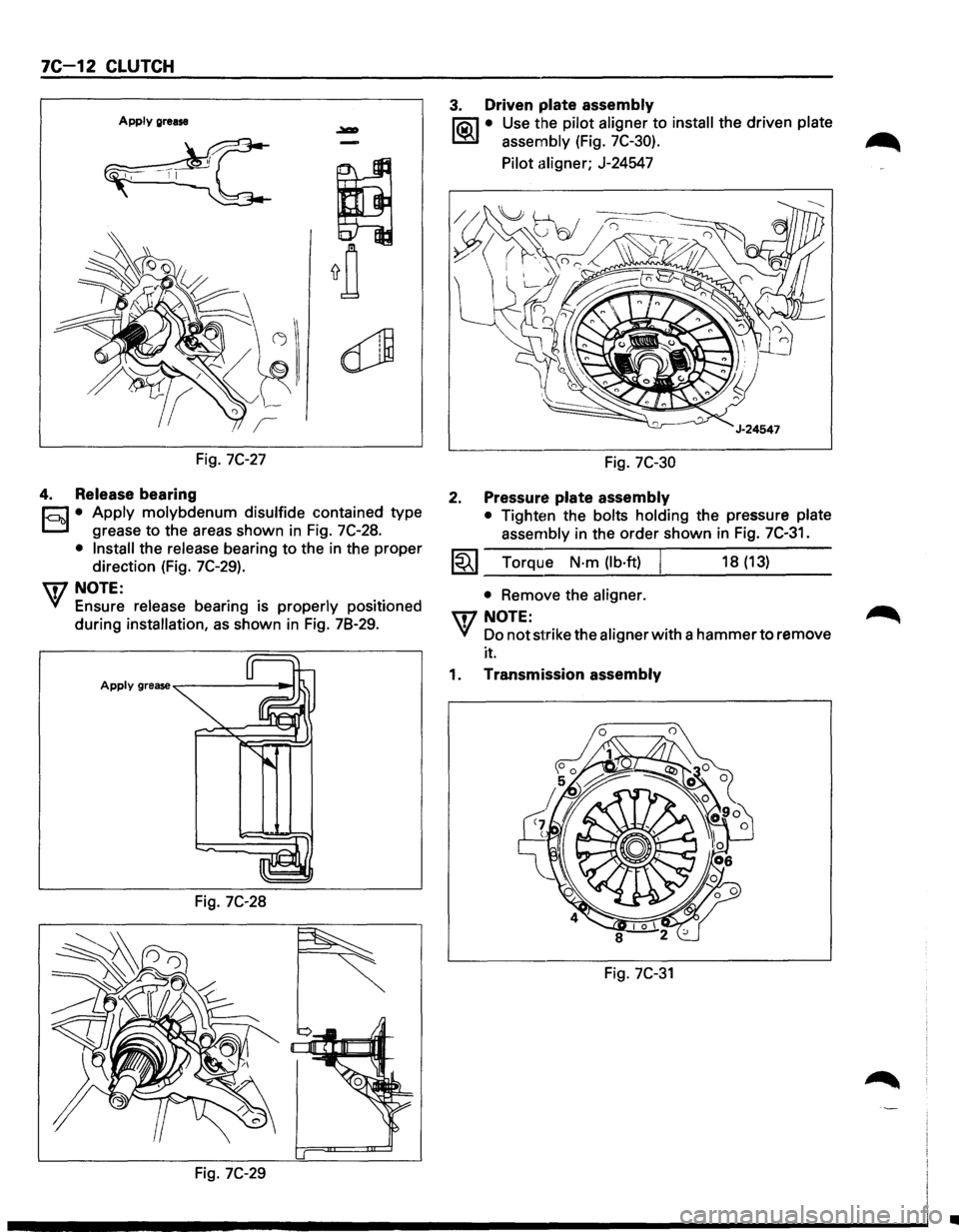
Apply grease
Fig. 7C-27
4. Release bearing
r;:J • Apply molybdenum disulfide contained type
D grease to the areas shown in Fig. 7C-28.
• Install the release bearing to the in the proper
direction (Fig.
7C-29).
U7 NOTE:
VI Ensure release bearing is properly positioned
during
installation, as shown in Fig. 78-29.
Fig. 7C-28
Fig. 7C-29
3. Driven plate assembly
liQ\1 • Use the pilot aligner to install the driven plate
~ assembly (Fig. 7C-30).
Pilot aligner; J-24547
Fig. 7C-30
2. Pressure plate assembly
• Tighten the bolts holding the pressure plate
assembly in the order shown in
Fig. 7C-31.
1~1 Torque N·m (lb·ft) I 18 (13)
• Remove the aligner.
UJNOTE:
VI Do not strike the aligner with a hammer to remove
it.
1. Transmission assembly
Fig. 7C-31
•
Page 1149 of 1928
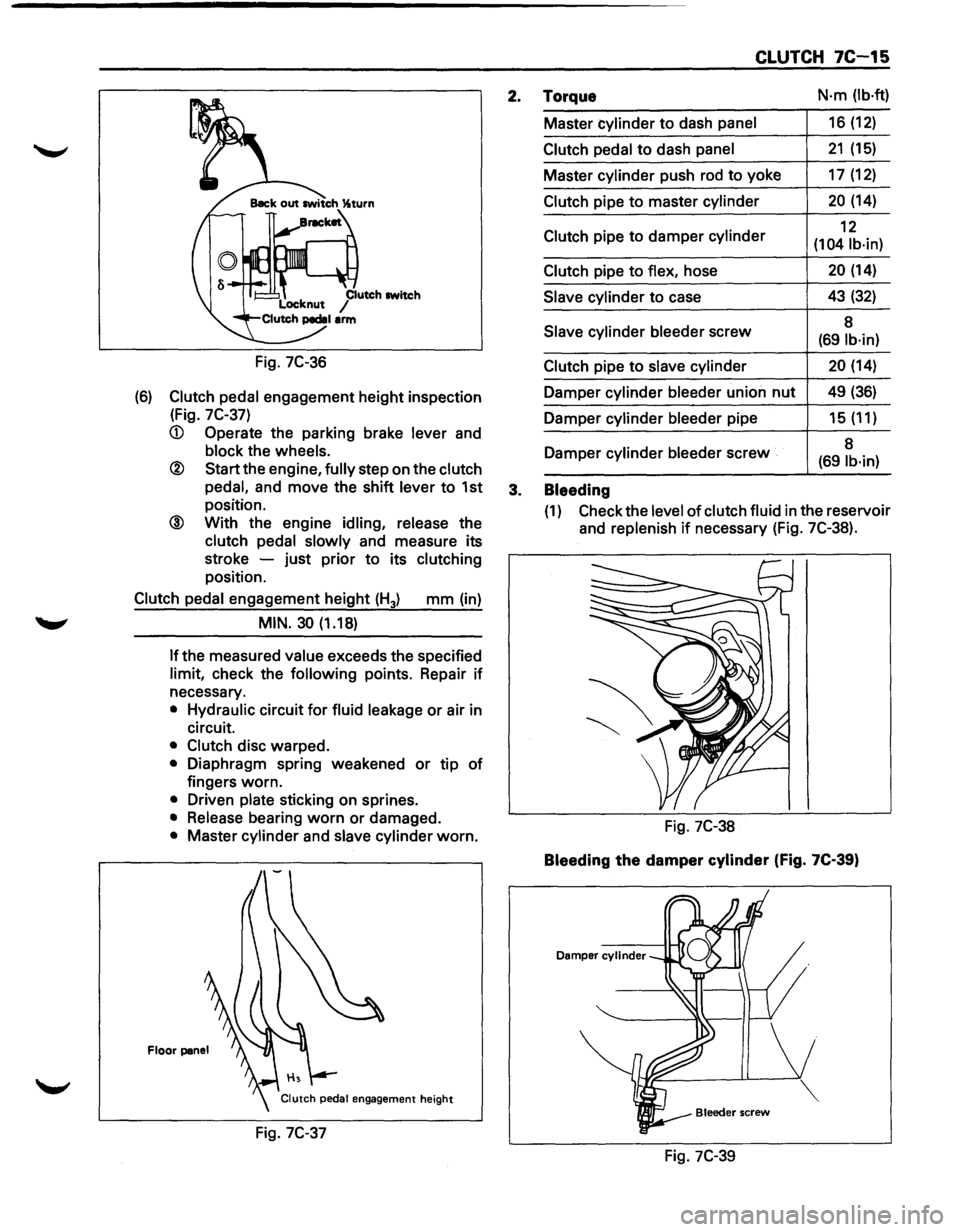
Fig. 7C-36
(6) Clutch pedal engagement height inspection
(Fig.
7C-37)
® Start the engine, fully step on the clutch
pedal,
and move the shift lever to 1st
position.
@ With the engine idling, release the
clutch pedal slowly and measure its
stroke -just prior
to its clutching
position.
Clutch pedal engagement height (H3) mm (in)
MIN. 30 (1.18)
If the
measured value exceeds the specified
limit, check the following points. Repair if
necessary.
• Hydraulic circuit for fluid leakage or air in
circuit.
• Clutch disc warped.
• Diaphragm spring weakened or tip of
fingers worn.
• Driven plate sticking on sprines.
• Release bearing worn or damaged.
• Master cylinder and slave cylinder worn.
Floor panel
Fig. 7C-37
CLUTCH 7C-15
2. Torque N·m (lb·ft)
Master cylinder to dash panel 16 (12)
Clutch pedal to dash panel 21 (15)
Master cylinder push rod to yoke 17 (12)
Clutch pipe to master cylinder 20 (14)
Clutch pipe
to damper cylinder 12
(104 lb·in)
Clutch
pipe to flex, hose 20 (14)
Slave cylinder to case 43 (32)
Slave
cylinder bleeder screw 8 (691b·in)
Clutch
pipe to slave cylinder 20 (14)
Damper cylinder bleeder union nut 49 (36)
Damper cylinder bleeder pipe 15 (11)
Damper cylinder
bleeder screw 8 (69 lb·in)
3. Bleeding
(1) Check
the level of clutch fluid in the reservoir
and
replenish if necessary (Fig. 7C-38).
Fig. 7C-38
Bleeding the damper cylinder (Fig. 7C-39)
Damper cylinder
Fig. 7C-39
Page 1156 of 1928
![ISUZU TROOPER 1995 Workshop Manual 7C-22 CLUTCH
TORQUE SPECIFICATIONS N·m (lb·ft)
76(56)]
Fig. 7C-52
•](/img/61/57183/w960_57183-1155.png "ISUZU TROOPER 1995 Workshop Manual 7C-22 CLUTCH
TORQUE SPECIFICATIONS N·m (lb·ft)
76(56)]
Fig. 7C-52
•")
7C-22 CLUTCH
TORQUE SPECIFICATIONS N·m (lb·ft)
76(56)]
Fig. 7C-52
•