lock ISUZU TROOPER 1995 Workshop Manual
[x] Cancel search | Manufacturer: ISUZU, Model Year: 1995, Model line: TROOPER, Model: ISUZU TROOPER 1995Pages: 1928
Page 884 of 1928
7A-12 AUTOMATIC TRANSMISSION (4L30-E)
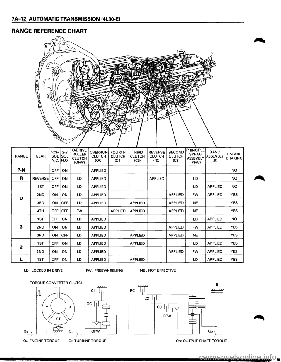
RANGE REFERENCE CHART
1-2/3-4 2-3 0/DRIVE OVERRUN FOURTH THIRD REVERSE SECOND BAND ROLLER ENGINE RANGE
GEAR SOL
SOL
CLUTCH CLUTCH
CLUTCH CLUTCH CLUTCH CLUTCH MBLY BRAKING N_c. N.O.
(OFW) (OCl
(C4)
(C3) (RC)
(C2) (B)
P-N OFF
ON APPLIED NO
R REVERSE OFF
ON LD APPLIED APPLIED LD NO
1ST OFF
ON LD APPLIED LD APPLIED NO
2ND ON ON LD APPLIED APPLIED FW APPLIED YES D 3RD ON
OFF LD APPLIED APPLIED APPLIED NE YES
4TH OFF OFF FW APPLIED APPLIED APPLIED NE YES
1ST OFF ON
LD APPLIED LD APPLIED NO
3 2ND ON ON LD APPLIED APPLIED FW APPLIED
YES
3RD ON OFF LD APPLIED APPLIED APPLIED NE YES
1ST OFF
ON LD APPLIED APPLIED LD APPLIED YES 2 2ND ON
ON LD APPLIED APPLIED FW APPLIED YES
L 1ST OFF
ON LD APPLIED APPLIED LD APPLIED
YES
LD : LOCKED IN DRIVE FW: FREEWHEELING NE : NOT EFFECTIVE
TORQUE CONVERTER CLUTCH
B
C4lil RC 1/f ~
C2 I I
C3
PFW ~
Qe OFW
Qe: ENGINE
TORQUE Qt: TURBINE TORQUE Qo: OUTPUT SHAFT TORQUE
Page 892 of 1928
7 A-20 AUTOMATIC TRANSMISSION (4L30-E)
CHECKING TRANSMISSION FLUID
LEVEL AND CONDITION
Checking fluid level and condition (color and odor)
at
regular intervals will provide early diagnosis
information about the transmission. This inform
ation may be used to correct a condition that, if not
detected early, could result in major transmission
repairs.
IMPORTANT: When new, automatic transmission
fluid is red in color. As the vehicle is driven, the
transmission
fluid will begin to look darker in color.
The
color may eventually appear light brown.
A DARK
brown color with burnt odor may indicate
excessive
fluid deterioration and signal a need for
fluid change.
FLUID LEVEL
When adding
or changing fluid, use only DEXRON
®-Ill.
Refer to the Maintenance and Lubrication (Section 0
of this manual) for maintenance information and
servicing
interval.
\f CAUTION: DO NOT OVERFILL
Overfilling will cause foaming, loss ~f fluid,
abnormal shifting and possible damage to
the transmission.
1. Start engine and drive vehicle until normal AfT
oil operating temperature is reached:
NOTE: The automatic transmission fluid level
must be checked with the vehicle at normal
A/T oil operating temperature: 75 TO 85°C
(167 TO 185°F) MEASURED WITH TECH1 SCAN
TOOL.
Temperature will greatly affect transmission
fluid level.
If the vehicle is not at normal AfT oil operating
temperature and the proper checking
procedures are
not followed, the result could
be a false reading of the fluid level indicator
and
an incorrect adjustment of the fluid level.
2. Park vehicle on level ground.
3. Move gear selector to "Park".
4. Apply parking brake and block wheels.
5. Allow vehicle to idle for 3 minutes with all
accessories turned off.
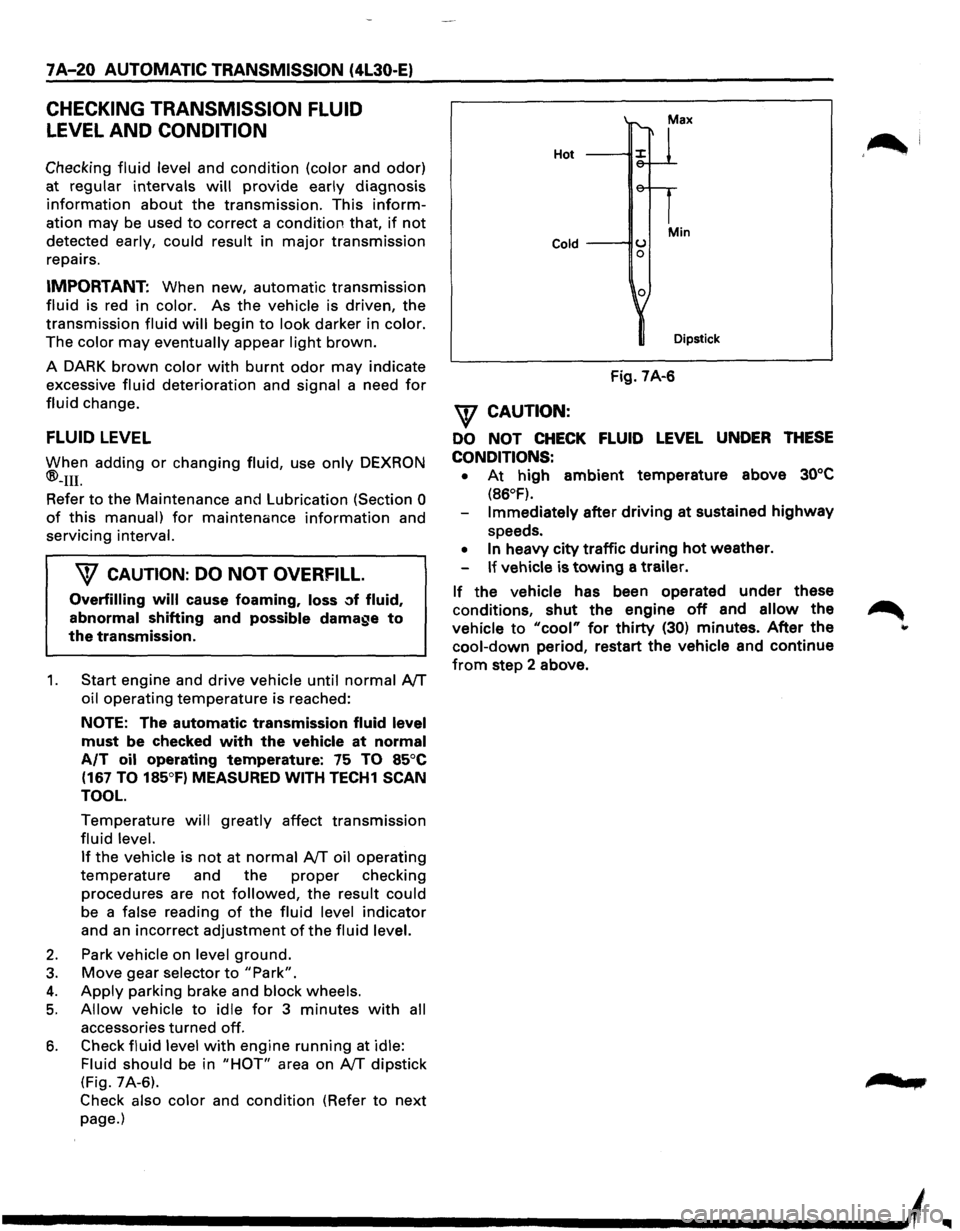
6. Check fluid level with engine running at idle:
Fluid should
be in "HOT" area on AfT dipstick
(Fig. 7A-6).
Check also color and condition (Refer to next
page.)
Hot
Cold ---IIU 0
0
Min
Dipstick
Fig. 7A-6
\f CAUTION:
DO NOT CHECK FLUID LEVEL UNDER THESE
CONDITIONS: •
At high ambient temperature above 30°C
(86°F).
Immediately after driving at sustained highway
speeds.
• In heavy city traffic during hot weather.
If vehicle is towing a trailer.
If the vehicle has been operated under these
conditions,
shut the engine off and allow the
vehicle to "cool" for thirty (30) minutes. After the
cool-down period, restart the vehicle and continue
from step 2 above.
'~I
......
Page 899 of 1928
AUTOMATIC TRANSMISSION (4l30-E) 7 A--27
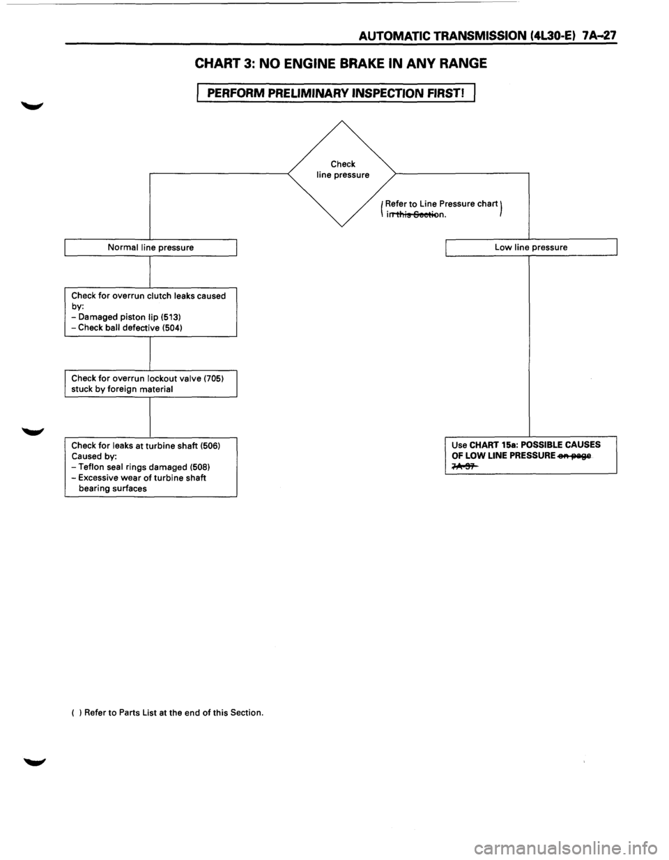
CHART 3: NO ENGINE BRAKE IN ANY RANGE
PERFORM PRELIMINARY INSPECTION FIRST!
Normal line pressure
Check for overrun clutch leaks caused
by:
-Damaged piston lip (513)
-Check ball defective (504)
Check for overrun lockout valve (705) stuck by foreign material
Check
for leaks at turbine shaft (506) Caused by: -Teflon seal rings damaged (508) -Excessive wear of turbine shaft
bearing surfaces
( ) Refer to Parts List at the end
of this Section.
Check
line pressure
(Refer
to Line
Pressure chart) irT'ti'lis Seetit>n.
Low line pressure
Use CHART 15a:
POSSIBLE CAUSES
OF LOW LINE PRESSURE eA fJ'Iil9&
~
Page 909 of 1928
w CJ s: a: w Cl)
w ..... CJ :E w > I z 0
AUTOMATIC TRANSMISSION (4L30..E) 7 A-37
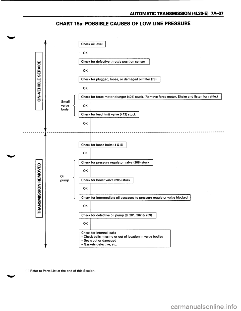
CHART 15a: POSSIBLE CAUSES OF LOW LINE PRESSURE
Small
valve
body
Oil pump
{
Check oil level I
OK
Check for defective throttle position sensor I
OK
Check for plugged, loose, or damaged oil filter (79) I
OK
Check for force motor plunger (404) stuck. (Remove force motor. Shake and listen for rattle.) I
OK
Check for feed limit valve (412) stuck I
OK
------------------------------------------------------------------------
Check for loose bolts (4 & 5) I
OK
Check for pressure regulator valve (208) stuck I
OK
Check for boost valve (205) stuck I
OK
Check for intermediate oil passages to pressure regulator valve blocked I
OK
Check for defective oil pump (9, 201, 202 & 209) I
OK
Check for internal leaks -Check balls missing or out of location in valve bodies -Seals cut or damaged
-Gaskets defective, etc.
( ) Refer to Parts List at the end
of this Section.
Page 913 of 1928
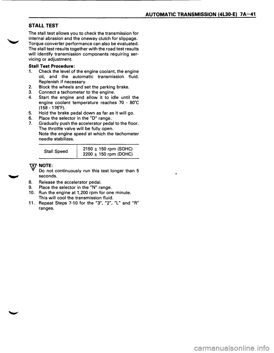
STALL TEST
The stall test allows you to check the transmission for
internal abrasion and the oneway clutch for slippage.
Torque converter performance can also be evaluated.
The
stall test results together with the road test results
will identify transmission components requiring ser
vicing or adjustment.
Stall Test Procedure:
1. Check the level of the engine coolant, the engine
oil, and the automatic transmission fluid.
Replenish
if necessary.
2. Block the wheels and set the parking brake.
3. Connect a tachometer to the engine.
4. Start the engine and allow it to idle until the
engine coolant temperature reaches
70 -8o·c
(158 -176.F).
5. Hold the brake pedal down as far as it will go.
6. Place the selector in the "D" range.
7. Gradually push the accelerator pedal to the floor.
The throttle valve
will be fully open.
Note the engine speed at which the tachometer
needle stabilizes.
Stall Speed
\fl NOTE:
2150 ± 150 rpm (SOHC)
2200 ± 150 rpm (DOHC)
VI Do not continuously run this test longer than 5
........, seconds.
8. Release the accelerator pedal.
9. Place the selector in the "N" range.
10. Run the engine at 1,200 rpm for one minute.
This
will cool the transmission fluid.
11. Repeat Steps 7-10 for the "3", "2", "L" and "R"
ranges.
AUTOMATIC TRANSMISSION (4L30-E) 7A-41
Page 914 of 1928
7 A-42 AUTOMATIC TRANSMISSION (4L30-E)
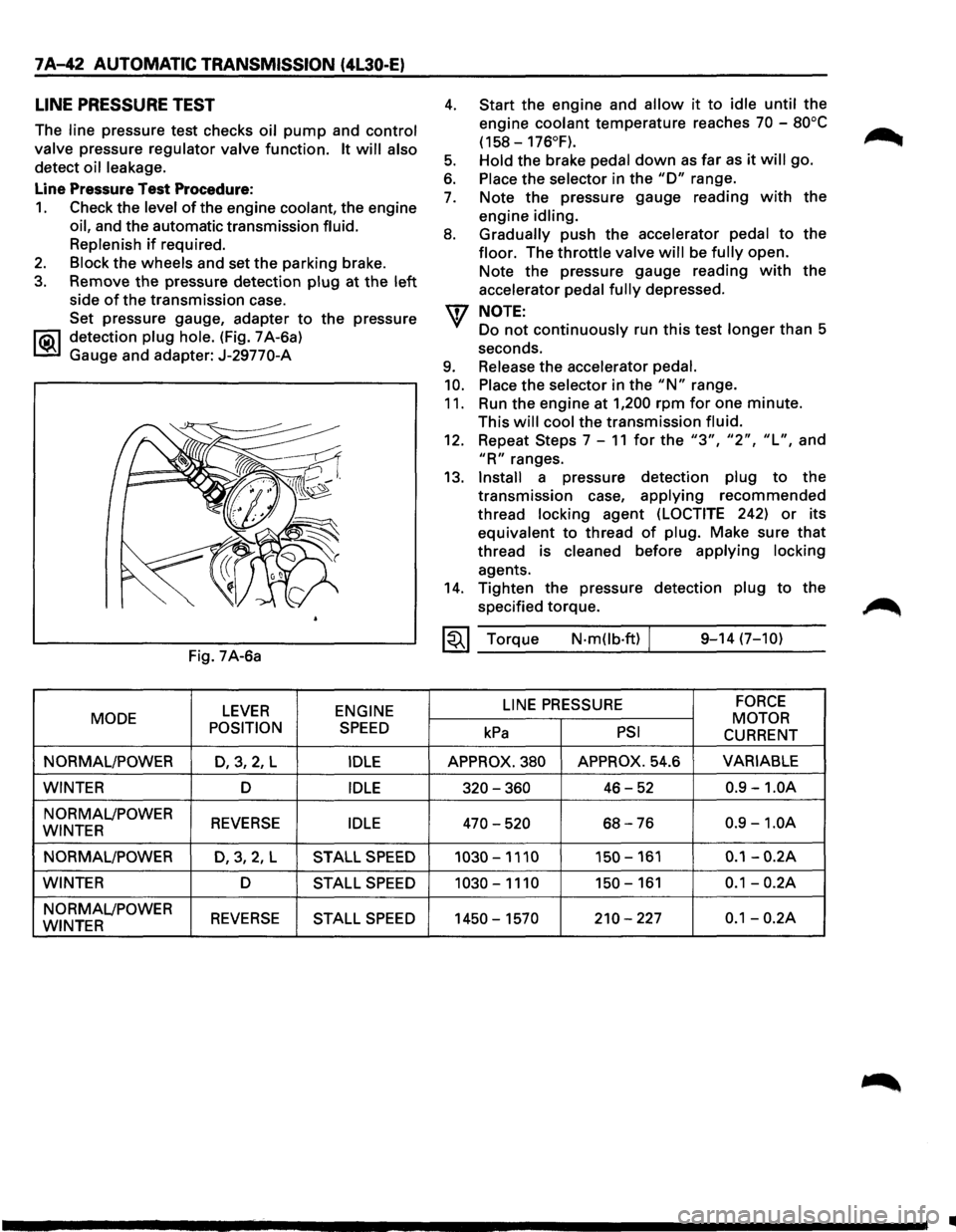
LINE PRESSURE TEST
The line pressure test checks oil pump and control
valve
pressure regulator valve function. It will also
detect oil leakage.
Line Pressure Test Procedure:
1. Check the level of the engine coolant, the engine
oil, and the automatic transmission fluid.
Replenish
if required.
2. Block the wheels and set the parking brake.
3. Remove the pressure detection plug at the left
side of the transmission case.
Set pressure gauge, adapter
to the pressure
l"iC\1 detection plug hole. (Fig. 7 A-6a)
~ Gauge and adapter: J-29770-A
Fig. 7A-6a
LEVER ENGINE
MODE
POSITION
SPEED
NORMAL/POWER D,3,2, L IDLE
WINTER D IDLE
NORMAL/POWER REVERSE IDLE WINTER
NORMAL/POWER
D,3,2,L STALL SPEED
WINTER D STALL SPEED
NORMAL/POWER REVERSE STALL SPEED WINTER
4.
5.
6.
7.
8.
9.
10.
11.
Start the engine and allow it to idle until the
engine
coolant temperature reaches 70 -80°C
(158-176°F).
Hold
the brake pedal down as far as it will go.
Place the selector in the "D" range.
Note the pressure gauge reading
with the
engine
idling.
Gradually
push the accelerator pedal to the
floor. The throttle valve will be fully open.
Note the pressure gauge reading
with the
accelerator
pedal fully depressed.
NOTE:
Do not continuously run this test longer than 5
seconds.
Release the accelerator pedal.
Place
the selector in the "N" range.
Run the engine at
1,200 rpm for one minute.
This
will cool the transmission fluid.
12. Repeat Steps 7-11 for the "3", "2", "L", and
"R" ranges.
13.
Install a pressure detection plug to the
transmission case,
applying recommended
thread
locking agent (LOCTITE 242) or its
equivalent to thread
of plug. Make sure that
thread is cleaned before applying locking
agents.
14. Tighten the pressure detection plug to the
specified torque.
~~~ Torque N·mOb·ft) / 9-14 (7-10)
LINE
PRESSURE FORCE
MOTOR kPa PSI CURRENT
APPROX. 380 APPROX. 54.6 VARIABLE
320-360 46-52 0.9 -1.0A
470-520 68-76 0.9 -1.0A
1030-1110 150-161 0.1-0.2A
1030-1110 150-161 0.1-0.2A
1450-1570 210-227 0.1-0.2A
•
Page 916 of 1928
7A-44 AUTOMATIC TRANSMISSION (4l30-E)
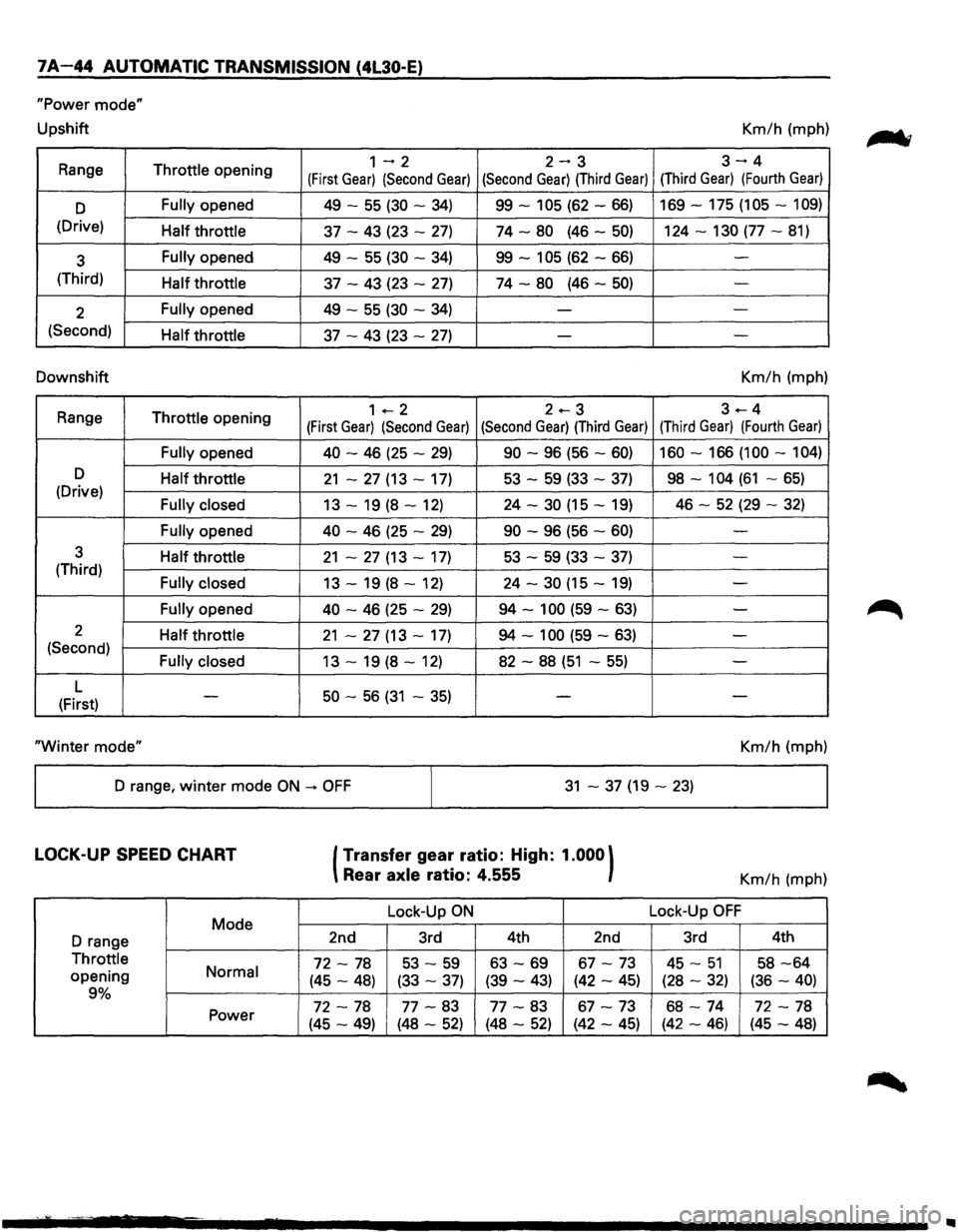
"Power mode"
Upshift Km/h (mph)
Range
Throttle opening 1-2 2-3 3-4
(First Gear) (Second Gear) (Second Gear) (Third Gear) (Third Gear) (Fourth Gear)
D Fully opened 49 -55 (30 -34) 99-105 (62-66) 169-175 (105-109)
(Drive) Half throttle 37 -43 (23 -27) 74-80 (46-50) 124-130 (77-81)
3 Fully opened
49 -55 (30 -34) 99-105 (62-66) -
(Third) Half throttle 37 -43 (23 -27) 74-80 (46-50) -
2 Fully opened
49 -55 (30 -34) --
(Second) Half throttle 37 -43 (23 -27) - -
Downshift Km/h (mph)
Range
Throttle opening 1 +--2 2.-3 3---4
(First Gear) (Second Gear) (Second Gear) (Third Gear) (Third Gear) (Fourth Gear)
Fully opened 40
-46 (25 -29) 90 -96 (56 -60) 160-166 (100-104)
D Half throttle 21 -27 (13 -17) 53 -59 (33 -37) 98-104 (61 -65) (Drive) Fully closed 13 -19 (8 -12) 24 -30 (15 -19) 46 -52 (29 -32)
Fully opened 40
-46 (25 -29) 90 -96 (56 -60) -
3 Half throttle 21 -27 (13 -17) 53 -59 (33 -37) -(Third) Fully closed 13 -19 (8 -12) 24 -30 (15 -19) -
Fully opened 40 -46 (25 -29) 94-100 (59-63) -
2 Half throttle 21 -27 (13 -17) 94-100 (59-63) -(Second) Fully closed 13 -19 (8 -12) 82 -88 (51 -55) -
L 50 -56 (31 -35) (First) -
--
"Winter
mode" Km/h (mph)
D range,
winter mode ON -+ OFF 31 -37 (19-23)
LOCK-UP SPEED CHART
Mode
D range
Throttle
opening Normal
9%
Power
(Transfer
gear ratio: High: 1.000)
Rear axle ratio: 4.555
Lock-Up ON
2nd 3rd 4th 2nd
72-78 53 -59 63-69 67-73
(45-48) (33-37) (39-43) (42-45)
72-78 77-83 77-83 67-73
(45-49) (48-52) (48-52) (42-45)
Km/h (mph)
Lock-Up
OFF
3rd 4th
45-51 58-64
(28-32) (36-40)
68-74 72-78
(42-46) (45-48)
..
Page 935 of 1928
AUTOMATIC TRANSMISSION (4L30-E) 7 A-63
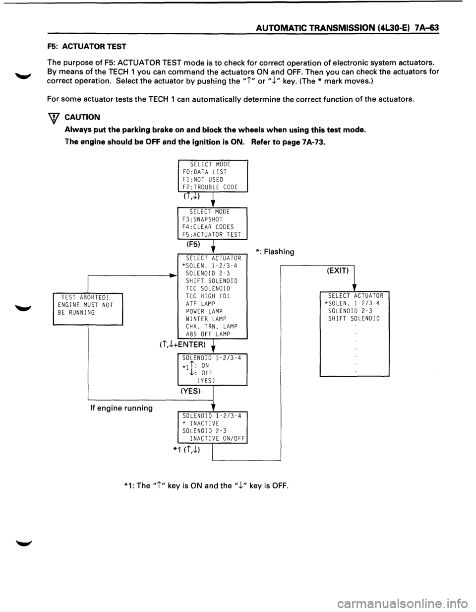
F5: ACTUATOR TEST
The purpose
of F5: ACTUATOR TEST mode is to check for correct operation of electronic system actuators.
By means of the TECH 1 you can command the actuators ON and OFF. Then you can check the actuators for
correct operation.
Select the actuator by pushing the "i" or".!." key. (The* mark moves.)
For some actuator tests the TECH 1
can automatically determine the correct function of the actuators.
W CAUTION
Always put the parking brake on and block the wheels when using this test mode.
The engine
should be OFF and the ignition is ON. Refer to page 7A-73.
TEST ABORTED! ENGINE MUST NOT BE RUNNING
If engine running
SELECT MODE FO: DATA LIST
F1:NOT USED F2:TROUBLE CODE
(T,.J..)
SELECT MODE
F3:SNAPSHOT F4:CLEAR CODES
F5:ACTUATOR TEST
(F5)
SELECT ACTUATOR *SOLEN. 1-2/3-4 SOLENOID 2-3
SHIFT SOLENOID TCC SOLENOID TCC HIGH CD)
ATF LAMP POWER LAMP WINTER LAMP
CHK. TRN. LAMP ABS OFF LAMP
(i,.!.+ENTER)
SOLENOID 1-2/3-4
*1 i: ON .j,: OFF
CYESJ
(YES)
SOLENOID 1-2/3-4 * INACTIVE SOLENOID 2-3 INACTIVE ON/OFF
* 1 (i,.!.)
*:Flashing
*1: The
"i" key is ON and the".!." key is OFF.
(EXIT)
SELECT ACTUATOR *SOLEN. 1-2/3-4 SOLENOID 2-3 SHIFT SOLENOID
Page 939 of 1928
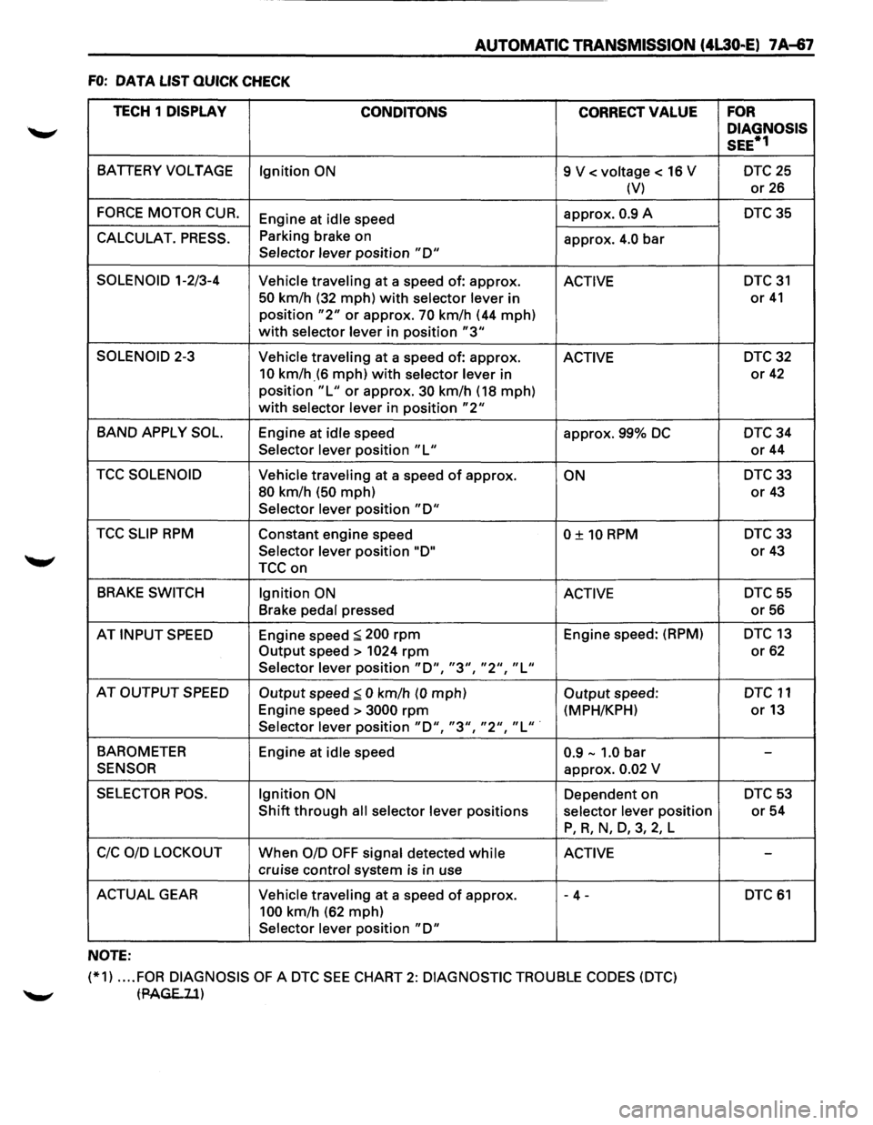
AUTOMATIC TRANSMISSION (4L30-E) 7 A~7
FO: DATA LIST QUICK CHECK
TECH 1
DISPLAY
CONDITONS CORRECT VALUE
BATIERY VOLTAGE
Ignition ON 9 V < voltage < 16 V
(V)
FORCE MOTOR CUR. Engine at idle speed approx. 0.9 A
CALCULAT. PRESS. Parking
brake on
approx. 4.0 bar Selector lever position "D"
SOLENOID 1-2/3-4
Vehicle traveling at a speed of: approx. ACTIVE
50 km/h (32 mph) with selector lever in
position
"2" or approx. 70 km/h (44 mph)
with selector lever in position "3"
SOLENOID 2-3
Vehicle traveling at a speed of: approx. ACTIVE
10 km/h_(6 mph) with selector lever in
position
"L" or approx. 30 km/h (18 mph)
with selector lever in position "2"
BAND APPLY SOL. Engine at idle speed
approx. 99% DC
Selector lever position "L"
TCC SOLENOID Vehicle traveling at a speed of approx. ON
80 km/h (50 mph)
Selector lever position "D"
TCC SLIP RPM Constant engine speed 0 ± 10 RPM
Selector lever position "D"
TCCon
BRAKE SWITCH
Ignition ON ACTIVE
Brake pedal pressed
AT
INPUT SPEED Engine speed :;:; 200 rpm Engine speed: (RPM)
Output speed> 1024 rpm
Selector lever position "D", "3", "2", "L"
AT OUTPUT SPEED Output speed:;:; 0 km/h (0 mph) Output speed:
Engine speed >
3000 rpm (MPH/KPH)
Selector lever position "D", "3", "2", "L" ·
BAROMETER
Engine at idle speed 0.9-1.0 bar
SENSOR approx. 0.02 V
SELECTOR POS. Ignition ON Dependent on
Shift through all selector lever positions selector lever position
P, R, N, D, 3, 2, L
C!C OlD LOCKOUT When 0/D OFF signal detected while ACTIVE
cruise control system is in use
ACTUAL GEAR Vehicle traveling at a speed of approx. - 4 -
100 km/h (62 mph)
Selector lever position
"D"
NOTE:
(*1) .... FOR DIAGNOSIS OF A DTC SEE CHART 2: DIAGNOSTIC TROUBLE CODES (DTC)
tPAGE..ll)
FOR
DIAGNOSIS
SEE*1
DTC25
or 26
DTC35
DTC 31
or 41
DTC32
or 42
DTC34
or 44
DTC33
or 43
DTC33
or 43
DTC55
or 56
DTC 13
or 62
DTC 11
or13
-
DTC53
or 54
-
DTC 61
Page 1019 of 1928
AUTOMATIC TRANSMISSION (4L30-E) 7A-147
TCM MEM-CAL REPLACEMENT
(TCM: Transmission Control Module)
1. MEM-CAL (Memory and Calibration Unit)
Information for specific transmission and vehicle is
programmed using an integrated circuit called a
MEM-CAL.
This allows one model of controller to be used for
many different vehicles.
The MEM-CAL is located inside the TCM and has
information on the transmission, shift map, etc.
several others.
2. MEM-CAL Replacement
If the diagnostic procedures require MEM-CAL
replacement,
the MEM-CAL should be replaced
using the following procedures.
NOTICE:
The ignition must be "OFF", when disconnecting or
reconnecting the TCM connector, to prevent
internal damage to the TCM.
NOTICE:
To prevent possible Electrostatic Discharge damage
to the TCM, do not touch the connector pins or
soldered components on the circuit board.
MEM-CAL Replacement Procedure:
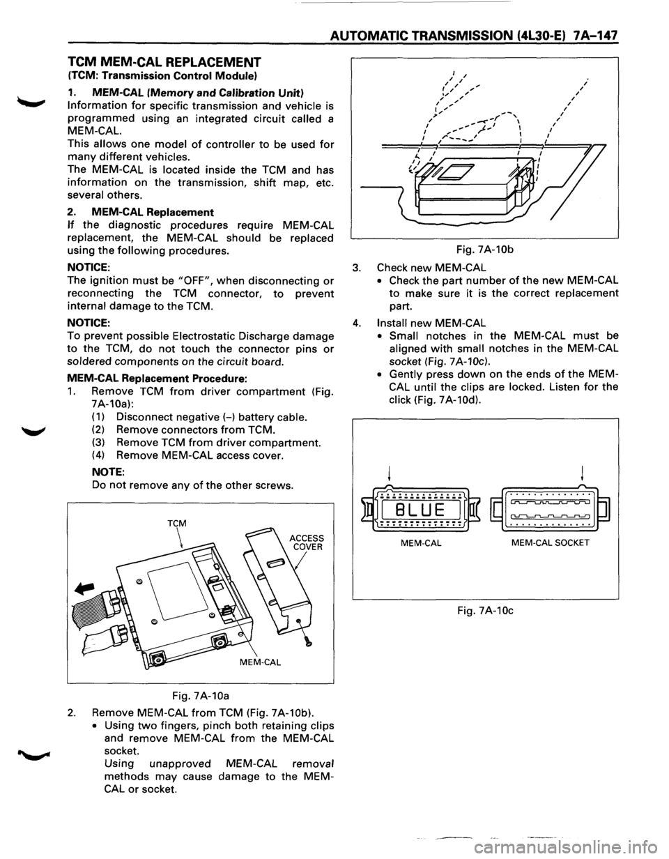
1. Remove TCM from driver compartment (Fig.
7A-10a):
( 1) Disconnect negative (-) battery cable.
(2) Remove connectors from TCM.
(3) Remove TCM from driver compartment.
(4) Remove MEM-CAL access cover.
NOTE:
Do not remove any of the other screws.
Fig.
7A-10a
2. Remove MEM-CAL from TCM (Fig. 7A-10b).
•
Using two fingers, pinch both retaining clips
and remove MEM-CAL from the MEM-CAL
socket.
Using unapproved
methods may cause
CAL or socket.
MEM-CAL removal
damage to the MEM- Fig.
7A-10b
3. Check new MEM-CAL
• Check
the part number of the new MEM-CAL
to make sure it is the correct replacement
part.
4. Install new MEM-CAL
• Small notches in the MEM-CAL must be
aligned with small notches in the MEM-CAL
socket (Fig.
7A-10c).
• Gently
press down on the ends of the MEM
CAL
until the clips are locked. Listen for the
click (Fig. 7A-10d).
! !
($I~rn~ ~~~) . . . . . . . . . . . . . . . ............ .
MEM-CAL MEM-CAL SOCKET
Fig. 7A-10c