ISUZU TROOPER 1995 Workshop Manual
Manufacturer: ISUZU, Model Year: 1995, Model line: TROOPER, Model: ISUZU TROOPER 1995Pages: 1928
Page 931 of 1928
AUTOMATIC TRANSMISSION (4l30-E) 7A-59
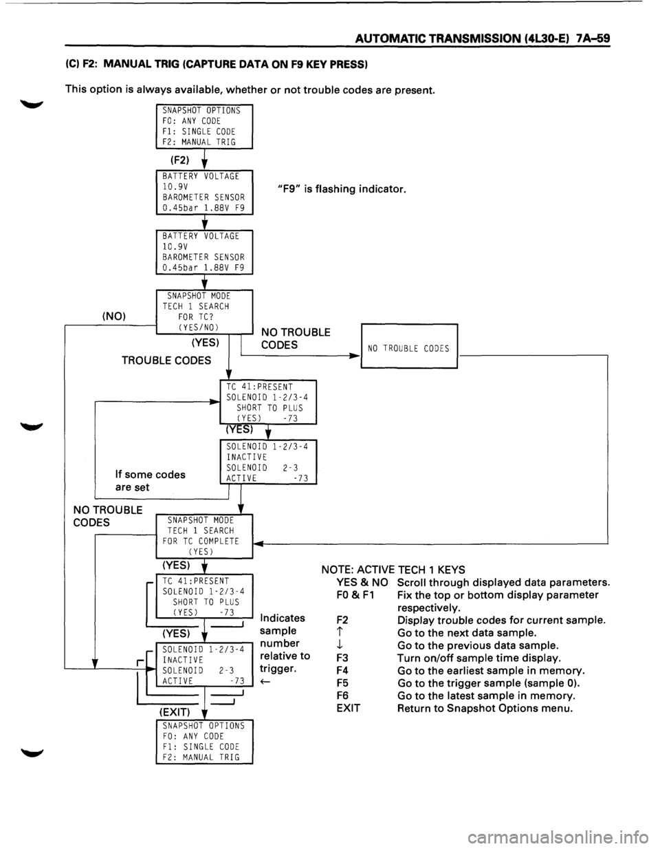
(C) F2: MANUAL TRIG (CAPTURE DATA ON F9 KEY PRESS)
This option is always available, whether or not trouble codes are present.
SNAPSHOT OPTIONS FO: ANY CODE Fl: SINGLE CODE F2: MANUAL TRIG
(F2)
BATTERY VOLTAGE
10.9V BAROMETER SENSOR 0.45bar 1.88V F9
"F9" is flashing indicator.
'
BATTERY VOLTAGE 10.9V BAROMETER SENSOR 0.45bar 1.88V F9
j_
SNAPSHOT MODE TECH 1 SEARCH (NO) FOR TC?
CYES/NOl
(YES)
TROUBLE CODES
NO TROUBLE
CODES
TC 41:PRESENT
.----------~· SOLENOID 1-2/3-4 SHORT TO PLUS
CYESl -73
(YES) y
SOLENOID 1-2/3-4
INACTIVE
If some codes
are set SOLENOID 2-3 ACTIVE -73
NO TROUBLE
CODES SNAPSHOT MODE
TECH 1 SEARCH FOR TC COMPLETE CYESl
NO TROUBLE CODES ..
(YES) j NOTE: ACTIVE TECH 1 KEYS r-TC 41: PRESENT SOLENOID 1-2/3-4
SHORT TO PLUS CYESl -73 I Indicates
(YES)
sample
r--~~:--":'"~~ number
r[ i~~g~0~ 1 -2
/3
-4 relative
to
'---...L----=--
1
~ soLEN~ I-D r-------l-2 _-~...;.7.;;..3 1
__, ~gger.
(EXIT)
SNAPSHOT OPTIONS FO: ANY CODE Fl: SINGLE CODE F2: MANUAL TRIG
YES & NO Scroll through displayed data parameters.
FO & F1 Fix the top or bottom display parameter
F2
I
J,
F3
F4
F5
F6
EXIT
respectively.
Display trouble codes for current sample.
Go to the next data sample.
Go to the previous data sample.
Turn
on/off sample time display.
Go to the earliest sample in memory.
Go to the trigger sample (sample 0).
Go to the latest sample in memory.
Return to Snapshot Options menu.
Page 932 of 1928
7 A-60 AUTOMATIC TRANSMISSION (4L30-E)
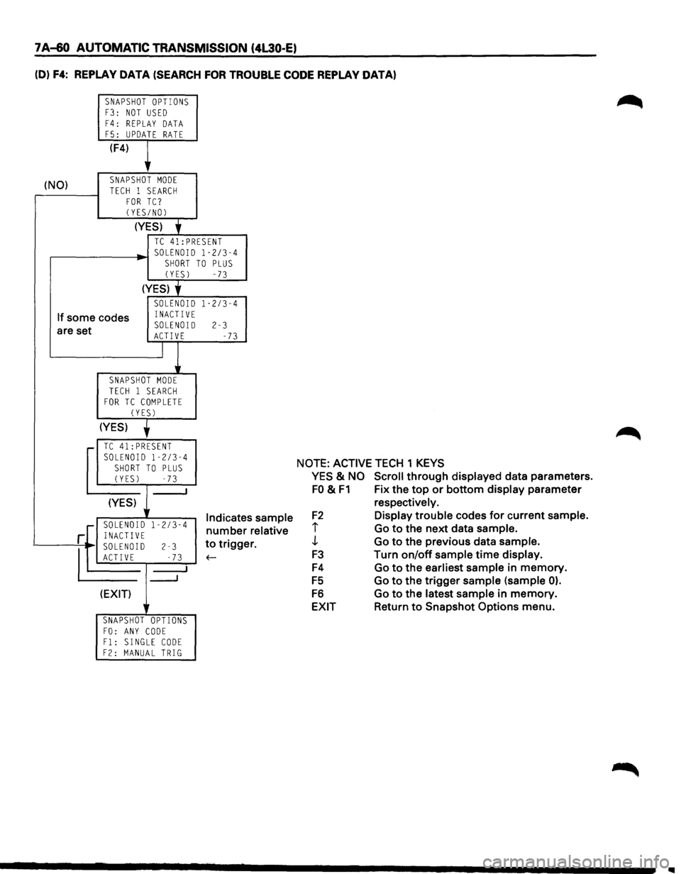
(D) F4: REPLAY DATA (SEARCH FOR TROUBLE CODE REPLAY DATA)
SNAPSHOT OPTIONS F3: NOT USED
F4: REPLAY DATA F5: UPDATE RATE
(F4)
,
(NO) SNAPSHOT MODE
TECH 1 SEARCH FOR TC? (YES/NOl
(YES)
• TC 41:PRESENT SOLENOID 1-2/3-4
SHORT TO PLUS (YES) -73
(YES) y
SOLENOID 1-2/3-4
If some codes INACTIVE
are set SOLENOID 2-3 ACTIVE -73
J
SNAPSHOT MODE TECH 1 SEARCH FOR TC COMPLETE
CYESl
(YES)
,.... TC 41:PRESENT
SOLENOID 1-2/3-4 SHORT TO PLUS (YES) -73
I
(YES) 1 Indicate 1-2/3-4 number ·[ SOLENOID r INACTIVE
~D
2-3
s sample
relative
r. to trigge
E -73 f-
___J
(EXIT)
r
SNAPSHOT OPTIONS FO: ANY CODE F1: SINGLE CODE F2: MANUAL TRIG
NOTE: ACTIVE TECH 1 KEYS
YES
& NO Scroll through displayed data parameters.
FO & F1 Fix the top or bottom display parameter
F2
i
J
F3
F4
FS
F6
EXIT
respectively.
Display trouble codes for current sample.
Go to the next data sample.
Go to the previous data sample.
Turn on/off sample time display.
Go to the earliest sample
in memory.
Go to the trigger sample (sample
0).
Go to the latest sample in memory.
Return to Snapshot
Options menu.
..
Page 933 of 1928
AUTOMATIC TRANSMISSION (4L30-E) 7 A-61
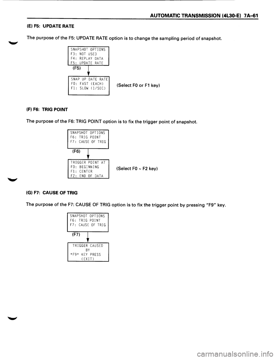
(E) F5: UPDATE RATE
The purpose of the
F5: UPDATE RATE option is to change the sampling period of snapshot.
SNAPSHOT OPTIONS F3: NOT USED F4: REPLAY DATA F5: UPDATE RATE
(F5)
l
SNAP UP DATE RATE FO: FAST (EACH)
Fl: SLOW (1/SECJ (Select FO or F1 key)
(f) F6: TRIG POINT
The purpose of the F6: TRIG POINT option is to fix the trigger point of snapshot.
SNAPSHOT OPTIONS F6: TRIG POINT F7: CAUSE OF TRIG
(F6)
l
TRIGGER POINT AT
FO: BEGINNING Fl: CENTER (Select FO -F2 key)
F2: END OF DATA
(G) F7: CAUSE OF TRIG
The purpose of the F7: CAUSE OF TRIG option is to fix the trigger point by pressing "F9" key.
SNAPSHOT OPTIONS F6: TRIG POINT F7: CAUSE OF TRIG
(F7)
T
TRIGGER CAUSED BY *F9* KEY PRESS (EXIT)
Page 934 of 1928
7 A-62 AUTOMATIC TRANSMISSION (4L30-E)
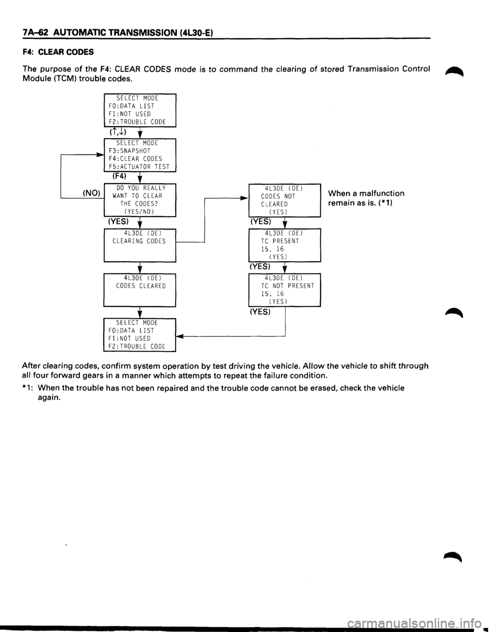
F4: CLEAR CODES
The purpose of the F4: CLEAR CODES mode is to command the clearing of stored Transmission Control ~
Module (TCM) trouble codes.
SELECT MODE FO:DATA LIST
F1:NOT USED F2:TROUBLE CODE
(i,J.)
'
SELECT MODE F3:SNAPSHOT
-F4:CLEAR CODES F5:ACTUATOR TEST
(F4)
' (NO) DO YOU REALLY WANT TO CLEAR THE CODES? (YES/NO)
(YES)
'
4L30E (DEl CLEARING CODES
'
4L30E (DE)
CODES CLEARED
'
SELECT MODE FO:DATA LIST F1:NOT USED
F2:TROUBLE CODE
..
-
4L30E (DEl
CODES NOT CLEARED (YES)
(YES)
'
4L30E (DEl TC PRESENT
15. 16 (YES)
(YES)
'
4L30E (DE)
TC NOT PRESENT
15. 16 (YESJ
(YES)
When a malfunction
remain
as is. (*1)
After clearing codes, confirm system operation by test driving the vehicle.
Allow the vehicle to shift through
all four forward gears in a manner which attempts to repeat the failure condition.
*1: When the trouble has not been repaired and the trouble code cannot
be erased, check the vehicle
again.
Page 935 of 1928
AUTOMATIC TRANSMISSION (4L30-E) 7 A-63
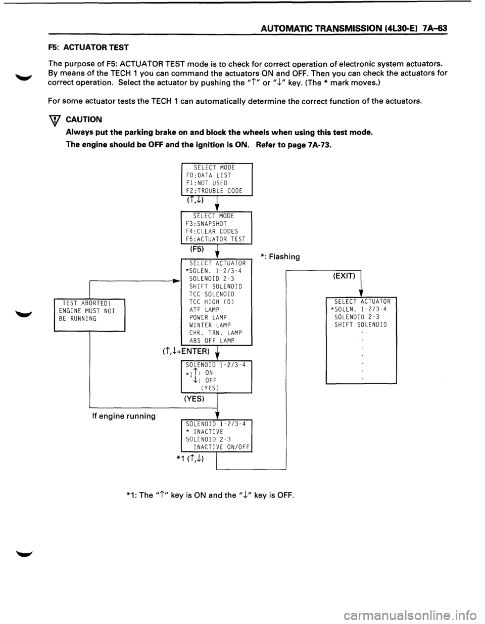
F5: ACTUATOR TEST
The purpose
of F5: ACTUATOR TEST mode is to check for correct operation of electronic system actuators.
By means of the TECH 1 you can command the actuators ON and OFF. Then you can check the actuators for
correct operation.
Select the actuator by pushing the "i" or".!." key. (The* mark moves.)
For some actuator tests the TECH 1
can automatically determine the correct function of the actuators.
W CAUTION
Always put the parking brake on and block the wheels when using this test mode.
The engine
should be OFF and the ignition is ON. Refer to page 7A-73.
TEST ABORTED! ENGINE MUST NOT BE RUNNING
If engine running
SELECT MODE FO: DATA LIST
F1:NOT USED F2:TROUBLE CODE
(T,.J..)
SELECT MODE
F3:SNAPSHOT F4:CLEAR CODES
F5:ACTUATOR TEST
(F5)
SELECT ACTUATOR *SOLEN. 1-2/3-4 SOLENOID 2-3
SHIFT SOLENOID TCC SOLENOID TCC HIGH CD)
ATF LAMP POWER LAMP WINTER LAMP
CHK. TRN. LAMP ABS OFF LAMP
(i,.!.+ENTER)
SOLENOID 1-2/3-4
*1 i: ON .j,: OFF
CYESJ
(YES)
SOLENOID 1-2/3-4 * INACTIVE SOLENOID 2-3 INACTIVE ON/OFF
* 1 (i,.!.)
*:Flashing
*1: The
"i" key is ON and the".!." key is OFF.
(EXIT)
SELECT ACTUATOR *SOLEN. 1-2/3-4 SOLENOID 2-3 SHIFT SOLENOID
Page 936 of 1928
7 A-64 AUTOMATIC TRANSMISSION (4L30-E)
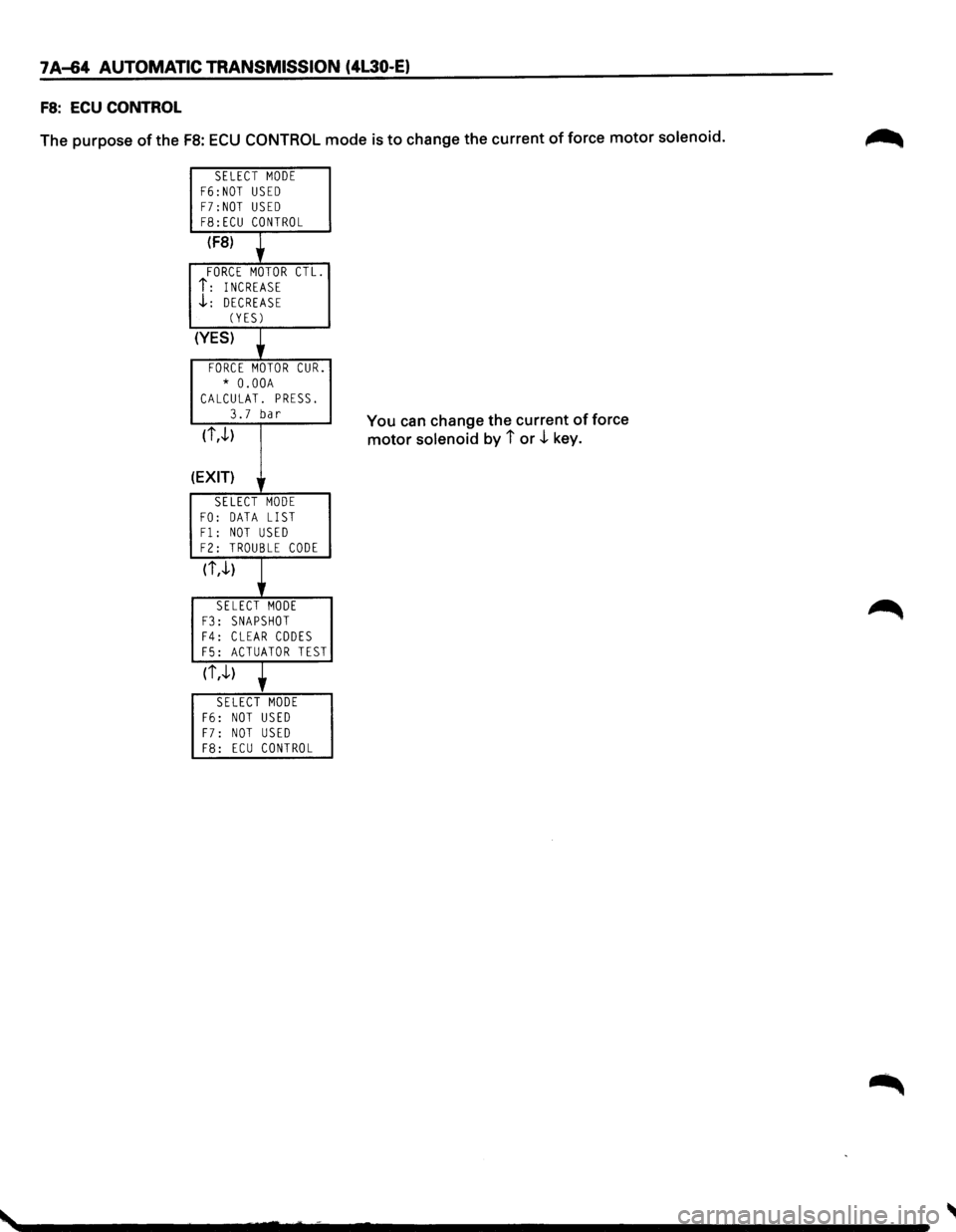
FS: ECU CONTROL
The purpose of the FB: ECU CONTROL mode is to change the current of force motor solenoid.
SELECT MODE F6:NOT USED F7:NOT USED F8:ECU CONTROL
(F8)
FORCE MOTOR CTL.
i: INCREASE .J..: DECREASE (YES)
(YES)
FORCE MOTOR CUR.
* O.OOA CALCULAT. PRESS.
3.7 bar
(i,.J..)
(EXIT) lr
SELECT MODE
FO: DATA LIST Fl: NOT USED F2: TROUBLE CODE
(i,.J..)
SELECT MODE F3: SNAPSHOT F4: CLEAR CODES F5: ACTUATOR TEST
(i,.J..)
SELECT MODE F6: NOT USED
F7: NOT USED F8: ECU CONTROL
You can change the current of force
motor solenoid by i or .J.. key.
Page 937 of 1928
CLEAR DTC
Remark: If you clear the DTC (Diagnosis Trouble
Codes) you will not be able to read any codes
recorded
during the last Trouble.
Remark: To be able to use the DTC again to identify
a problem you will need to reproduce the fault or
the problem. This may require a new test drive or
just turning the ignition on (this depends on the
nature
of the fault).
1. IF you have a TECH1:
(1) Connect the TECH1 if it is still not con-
nected
GOTHROUGH TECH1 CON-
NECTION.
(2) Push "F4" and answer "Yes" to the
question
"Do you really want to clear the
codes?"
CD When a malfunction remains as it is
the
TECH 1 displays "4L30E CODES
NOT
CLEARED". This means that the
problem is still there or that the
recovery was
not done please GOTO
DTCCHECK.
® When a malfunction has been re
paired and the recovery is
done the
TECH1 displays "4L30E CODES
CLEARED".
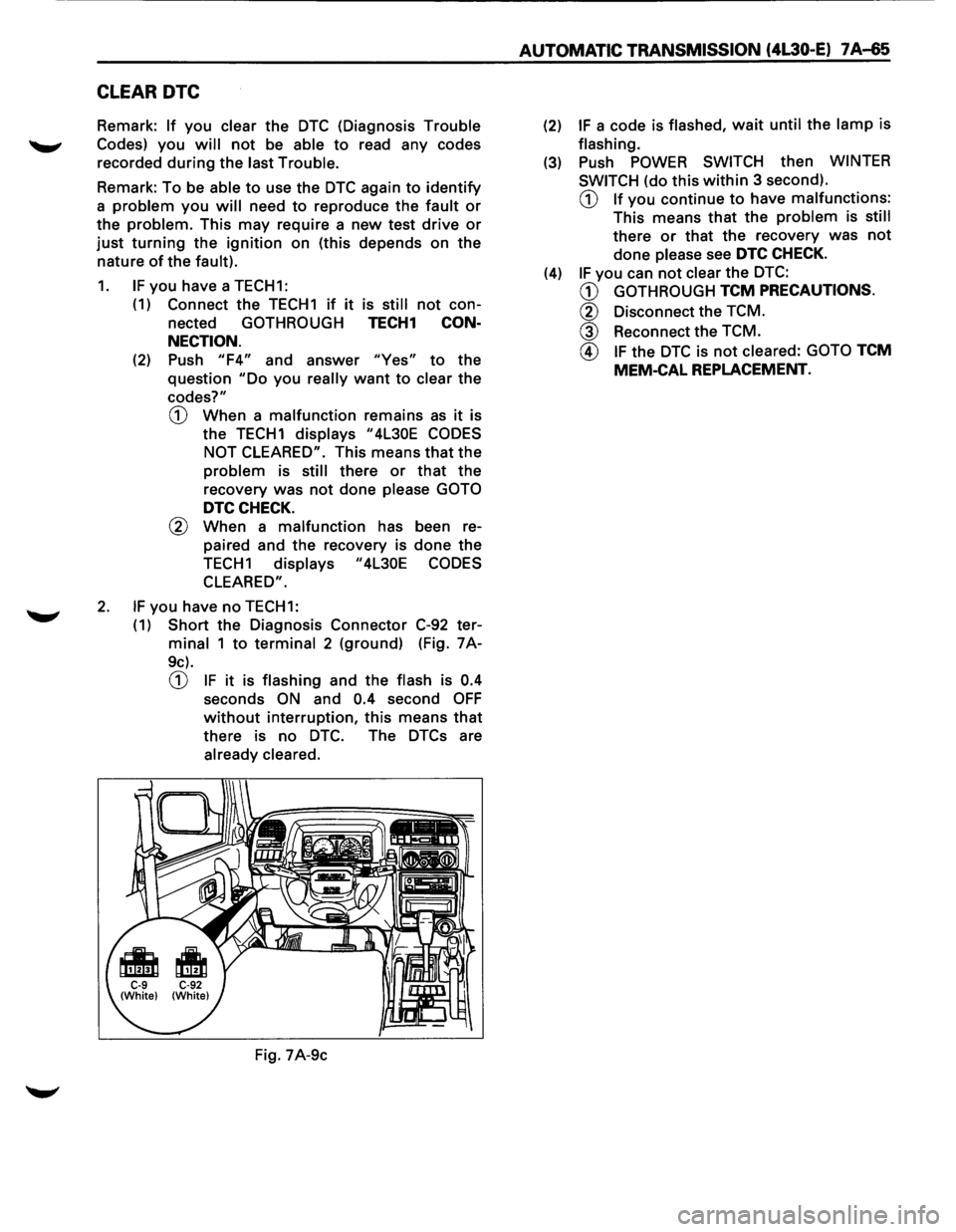
2. IF you have no TECH1:
(
1) Short the Diagnosis Connector C-92 ter
minal 1 to terminal 2 (ground) (Fig. 7A-
9c).
CD IF it is flashing and the flash is 0.4
seconds ON and 0.4 second OFF
without interruption, this means that
there is no DTC. The DTCs are
already cleared.
Fig. 7A-9c
AUTOMATIC TRANSMISSION (4L30-E) 7 A-65
(2) IF a code is flashed, wait until the lamp is
flashing.
(3) Push POWER SWITCH then WINTER
SWITCH
(do this within 3 second).
CD If you continue to have malfunctions:
This means that the problem is still
there or that the recovery was not
done please see DTC CHECK.
(4) IF you can not clear the DTC:
CD GOTHROUGH TCM PRECAUTIONS.
@ Disconnect the TCM.
@ Reconnect the TCM.
@ IF the DTC is not cleared: GOTO TCM
MEM-CAL REPLACEMENT.
Page 938 of 1928
7 A-66 AUTOMATIC TRANSMISSION (4L30-E)
DTCCHECK
1 Diagnosis Trouble Codes (DTC) have been
identified
by TECH1 or FLASHING CODES.
2. You have written the list of the DTC. The order
of the malfunctions has no meanings for this
TCM. Usually only one or two malfunctions
should
be set for a given problem.
3. Check directly the DTCs you identified. The
DTC are sorted by number. See Chart 2:
DIAGNOSTIC TROUBLE CODES (Page 7A-71).
'
Page 939 of 1928
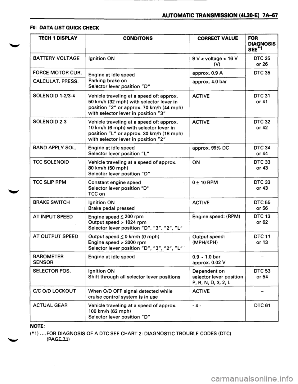
AUTOMATIC TRANSMISSION (4L30-E) 7 A~7
FO: DATA LIST QUICK CHECK
TECH 1
DISPLAY
CONDITONS CORRECT VALUE
BATIERY VOLTAGE
Ignition ON 9 V < voltage < 16 V
(V)
FORCE MOTOR CUR. Engine at idle speed approx. 0.9 A
CALCULAT. PRESS. Parking
brake on
approx. 4.0 bar Selector lever position "D"
SOLENOID 1-2/3-4
Vehicle traveling at a speed of: approx. ACTIVE
50 km/h (32 mph) with selector lever in
position
"2" or approx. 70 km/h (44 mph)
with selector lever in position "3"
SOLENOID 2-3
Vehicle traveling at a speed of: approx. ACTIVE
10 km/h_(6 mph) with selector lever in
position
"L" or approx. 30 km/h (18 mph)
with selector lever in position "2"
BAND APPLY SOL. Engine at idle speed
approx. 99% DC
Selector lever position "L"
TCC SOLENOID Vehicle traveling at a speed of approx. ON
80 km/h (50 mph)
Selector lever position "D"
TCC SLIP RPM Constant engine speed 0 ± 10 RPM
Selector lever position "D"
TCCon
BRAKE SWITCH
Ignition ON ACTIVE
Brake pedal pressed
AT
INPUT SPEED Engine speed :;:; 200 rpm Engine speed: (RPM)
Output speed> 1024 rpm
Selector lever position "D", "3", "2", "L"
AT OUTPUT SPEED Output speed:;:; 0 km/h (0 mph) Output speed:
Engine speed >
3000 rpm (MPH/KPH)
Selector lever position "D", "3", "2", "L" ·
BAROMETER
Engine at idle speed 0.9-1.0 bar
SENSOR approx. 0.02 V
SELECTOR POS. Ignition ON Dependent on
Shift through all selector lever positions selector lever position
P, R, N, D, 3, 2, L
C!C OlD LOCKOUT When 0/D OFF signal detected while ACTIVE
cruise control system is in use
ACTUAL GEAR Vehicle traveling at a speed of approx. - 4 -
100 km/h (62 mph)
Selector lever position
"D"
NOTE:
(*1) .... FOR DIAGNOSIS OF A DTC SEE CHART 2: DIAGNOSTIC TROUBLE CODES (DTC)
tPAGE..ll)
FOR
DIAGNOSIS
SEE*1
DTC25
or 26
DTC35
DTC 31
or 41
DTC32
or 42
DTC34
or 44
DTC33
or 43
DTC33
or 43
DTC55
or 56
DTC 13
or 62
DTC 11
or13
-
DTC53
or 54
-
DTC 61
Page 940 of 1928
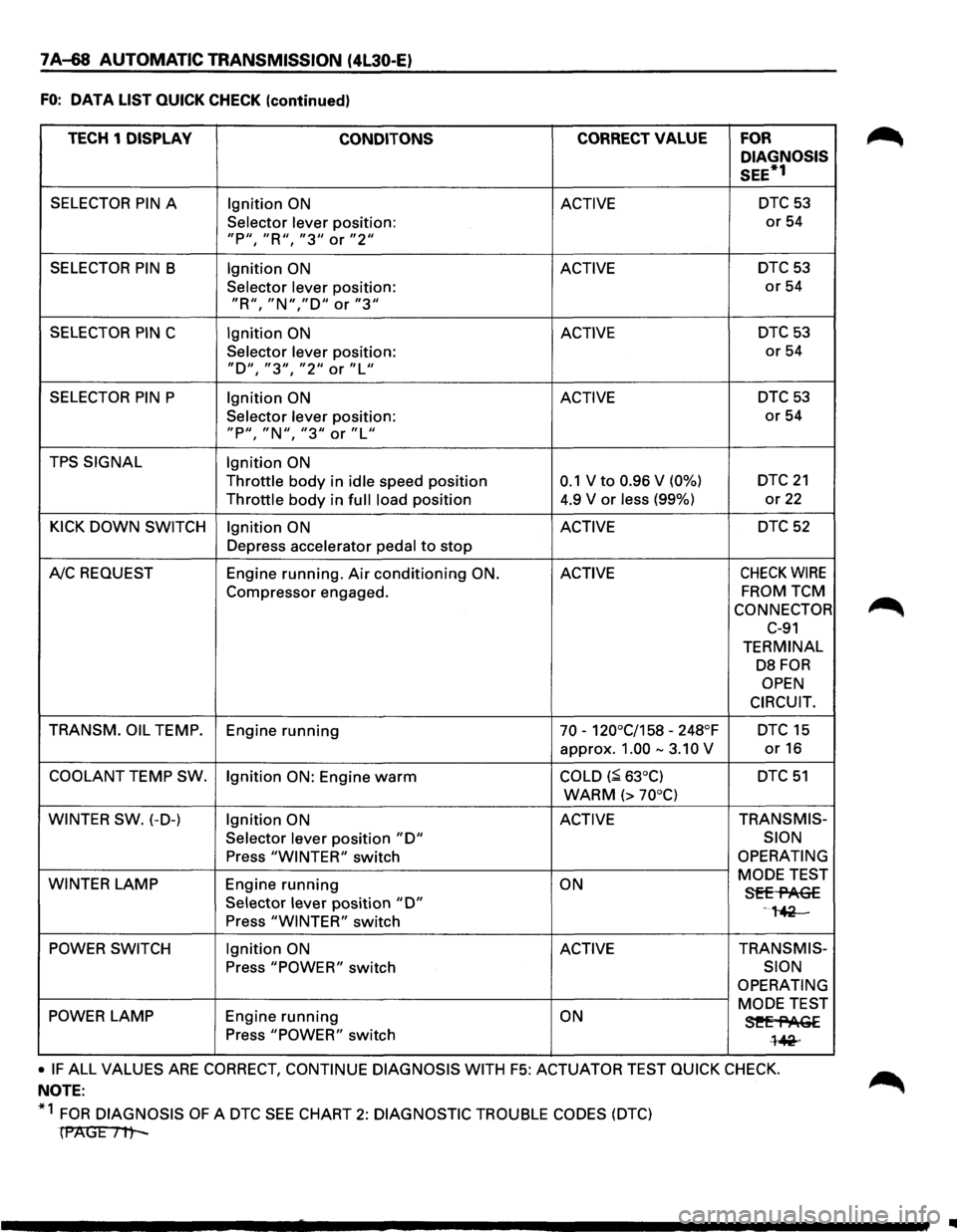
7A-68 AUTOMATIC TRANSMISSION (4l30-E)
FO: DATA LIST QUICK CHECK (continued)
TECH 1 DISPLAY
CONDITONS CORRECT VALUE FOR
DIAGNOSIS
SEE*1
SELECTOR PIN A Ignition ON ACTIVE DTC 53
Selector lever position: or 54
"P11, "R'', "311 or "211
SELECTOR PIN B Ignition ON ACTIVE DTC53
Selector lever position: or 54
"R11
, "N","D'' or "3''
SELECTOR PIN C Ignition ON ACTIVE DTC 53
Selector lever position: or 54
"D'', "311
, "211 or "L''
SELECTOR PIN P Ignition ON ACTIVE DTC 53
Selector lever position: or 54
"P11
, "N11, "311 or "Lu
TPS SIGNAL Ignition ON
Throttle body in idle speed position 0.1 V to 0.96 V (0%) DTC 21
Throttle body in full load position 4.9
V or less (99%) or 22
KICK DOWN SWITCH Ignition ON ACTIVE DTC 52
Depress accelerator pedal to stop
A!C REQUEST Engine running. Air conditioning ON. ACTIVE CHECK WIRE
Compressor
engaged. FROM TCM
CONNECTOR
C-91
TERMINAL
DB FOR
OPEN
CIRCUIT.
TRANSM. OIL
TEMP.
Engine running 70 -120°C/158 -248°F DTC 15
approx. 1.00 -3.10 V or16
COOLANT TEMP SW.
Ignition ON: Engine warm COLD (~ 63°C) DTC 51
WARM (> 70°C)
WINTER SW.
(-D-) Ignition ON ACTIVE TRANS
MIS-
Selector
lever position "D" SION
Press "WINTER" switch OPERATING
WINTER
LAMP Engine running ON MODE
TEST Sff-flAG£ Selector lever position "D" -,~ Press "WINTER" switch
POWER SWITCH Ignition ON ACTIVE TRANSMIS-
Press "POWER" switch SION
OPERATING
POWER LAMP Engine running ON MODE TEST
3!'Ef'AGE Press "POWER" switch l~·
• IF ALL VALUES ARE CORRECT, CONTINUE DIAGNOSIS WITH F5: ACTUATOR TEST QUICK CHECK.
NOTE:
*1
FOR DIAGNOSIS OF A DTC SEE CHART 2: DIAGNOSTIC TROUBLE CODES (DTC)
(PAGE Itt-
IIIII