JAGUAR X308 1998 2.G Workshop Manual
Manufacturer: JAGUAR, Model Year: 1998, Model line: X308, Model: JAGUAR X308 1998 2.GPages: 2490, PDF Size: 69.81 MB
Page 1231 of 2490
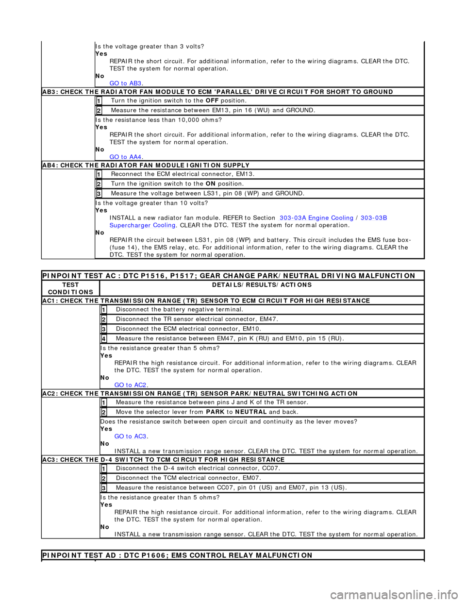
Is th
e voltage greater than 3 volts?
Yes REPAIR the short circuit. For addi tional information, refer to the wiring diagrams. CLEAR the DTC.
TEST the system for normal operation.
No GO to AB3
.
AB3
: CHECK THE RADIATOR FAN MODULE TO ECM
'PARALLEL' DRIVE CIRCUIT FOR SHORT TO GROUND
Turn the ignition swi
tch to the OFF
position.
1
Meas
ure the resistance between EM13, pin 16 (WU) and GROUND.
2
Is
the resistance less than 10,000 ohms?
Yes
REPAIR the short circuit. For addi tional information, refer to the wiring diagrams. CLEAR the DTC.
TEST the system for normal operation.
No GO to AA4
.
AB4
: CHECK THE RADIATOR FAN MODULE IGNITION SUPPLY
Re
connect the ECM electrical connector, EM13.
1
Turn the ignition swi
tch to the ON
position.
2
Measure the
voltage between LS
31, pin 08 (WP) and GROUND.
3
Is the vol
tage greater than 10 volts?
Yes INSTALL a new radiator fan module. REFER to Section 303
-0
3A Engine Cooling
/
30
3
-03
B
Supercharger
Cooling
. CLEA
R the DTC. TEST the sy
stem for normal operation.
No REPAIR the circuit between LS31, pin 08 (WP) and battery. This circuit includes the EMS fuse box-
(fuse 14), the EMS relay, etc. For additional information, refer to the wiring diagrams. CLEAR the
DTC. TEST the system for normal operation.
P
INPOINT TEST AC : DTC P1516, P1517; GEAR
CHANGE PARK/NEUTRAL DRIVING MALFUNCTION
TE
ST
CONDITIONS
D
ETAILS/RESULTS/ACTIONS
AC1: CH
ECK THE TRANSMISSION RANGE (TR) SE
NSOR TO ECM CIRCUIT FOR HIGH RESISTANCE
Di
sconnect the battery negative terminal.
1
Di
sconnect the TR sensor el
ectrical connector, EM47.
2
D
isconnect the ECM electrical connector, EM10.
3
Meas
ure the resistance between EM47, pin K (RU) and EM10, pin 15 (RU).
4
Is th
e resistance greater than 5 ohms?
Yes REPAIR the high resistance circui t. For additional information, refer to the wiring diagrams. CLEAR
the DTC. TEST the system for normal operation.
No GO to AC2
.
AC2: CH
ECK THE TRANSMISSION RANGE (TR)
SENSOR PARK/NEUTRAL SWITCHING ACTION
Meas
ure the resistance between pi
ns J and K of the TR sensor.
1
Mo
ve the selector lever from
PARK to NEUTRAL and back.
2
D
oes the resistance switch between open ci
rcuit and continuity as the lever moves?
Yes GO to AC3
.
No
INSTALL a new transmission range sensor. CLEAR th e DTC. TEST the system for normal operation.
AC3: CH
ECK THE D-4 SWITCH TO
TCM CIRCUIT FOR HIGH RESISTANCE
Di
sconnect the D-4 switch electrical connector, CC07.
1
Di
sconnect the TCM electrical connector, EM07.
2
Meas
ure the resistance between CC07,
pin 01 (US) and EM07, pin 13 (US).
3
Is th
e resistance greater than 5 ohms?
Yes REPAIR the high resistance circui t. For additional information, refer to the wiring diagrams. CLEAR
the DTC. TEST the system for normal operation.
No INSTALL a new transmission range sensor. CLEAR th e DTC. TEST the system for normal operation.
P
INPOINT TEST AD : DTC P1606;
EMS CONTROL RELAY MALFUNCTION
Page 1232 of 2490

TES
T
CONDITIONS
D E
TAILS/RESULTS/ACTIONS
AD1
:
CHECK THE EMS RELAY PERMANENT B+ SUPPLY
R
e
move the EMS relay.
1
Meas
ure t
he voltage between the rela
y base, pins 02 and 03 and GROUND.
2
Are both vol
tages greater than 10 volts?
Yes GO to AD2
.
No
R
EPAIR the circuit between the rela
y base and battery. This circuit includes the high power protection
module. For additional information, refer to the wiring diagrams. CLEAR the DTC. TEST the system
for normal operation.
AD2 :
CHECK THE EMS RELAY TO ECM CIRCUIT FOR HIGH RESISTANCE
Di
sc
onnect the battery negative terminal.
1
D
i
sconnect the ECM electrical connector, EM10.
2
Meas
ure t
he resistance between the rela
y base, pin 01 and EM10, pin 16 (PK).
3
Is the res
istance greater than 5 ohms?
Yes REPAIR the high resistance circui t. For additional information, refer to the wiring diagrams. CLEAR
the DTC. TEST the system for normal operation.
No INSTALL a new EMS relay. CLEAR the DTC. TEST the system for normal operation.
PINPOINT TEST AE : CHECK
ROCHESTER VALVE FUNCTION
T
E
ST CONDITIONS
D
E
TAILS/RESULTS/ACTIONS
AE1: CHEC
K VAC
UUM INTEGRITY OF ROCHESTER VALVE
Di
sc
onnect hoses from the Rochester valve.
1
Bl
a
nk off outlet side of valve.
2
Con
n
ect a hand-held vacuum pump to the vacuum inlet of the valve.
3
Appl
y a vacuum t
o the valve and mo
nitor the reading for 2 minutes.
4
Do
es the valve hold vacuum?
Yes Inspect the pipes at either side of the valve for leaks/damage. Rectify as necessary.
No INSTALL a new Rochester valve. TEST the system for normal operation.
Page 1233 of 2490
E
lectronic Engine Controls - Ca
mshaft Position (CMP) Sensor
Re
moval and Installation
Remov
al
1.
Disc
onnect battery ground cable (IMPORTANT, see SRO
86.15.19 for further information).
2. Remove engine covers ; refer to 12.30.06.
3. WARNING: BEFORE PROCEEDING, IT IS ESSENTIAL THAT
THE WARNING NOTES GIVEN IN SECTION 100-00 (UNDER THE
HEADING 'SAFETY PRECAUTIONS') ARE READ AND
UNDERSTOOD.
De-pressurize fuel system; refer to 19.50.02.
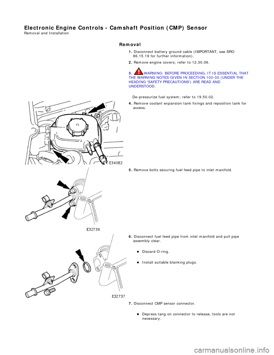
4. R
emove coolant expansion tank fixings and reposition tank for
access.
5. R
emove bolts securing fuel fe
ed pipe to inlet manifold.
6. Di
sconnect fuel feed pipe from inlet manifold and pull pipe
assembly clear.
Di
scard O-ring.
Inst
all suitable blanking plugs.
7. Disconnect CMP sensor connector.
De
press tang on connector to release, tools are not
necessary.
Page 1234 of 2490

In
stallation
8.
Relea
se CMP sensor socket
from mounting bracket.
De
press tang on socket to release, tools are not
necessary.
9. Remo
ve CMP sensor.
R
e
move fixing.
Re
mo
ve sensor.
Di
sc
ard O-ring.
Inst
al
l suitable blanking plug.
1. Instal
l CMP sensor.
Cl
ean relevant parts and mating faces.
Re
move blanking plug.
Install and lubricate new O-ri
ng.
2. Install CMP sensor socket to mounting bracket.
Page 1235 of 2490

3. Conne
ct CMP sensor connector.
4. Connect
fuel feed pipe to inlet manifold.
R
emove blanking plugs.
Install and lubricate new O-r
ing.
5. Install
bolts securing fuel feed
pipe to the inlet manifold.
6. Install coolant expansion tank.
Page 1236 of 2490
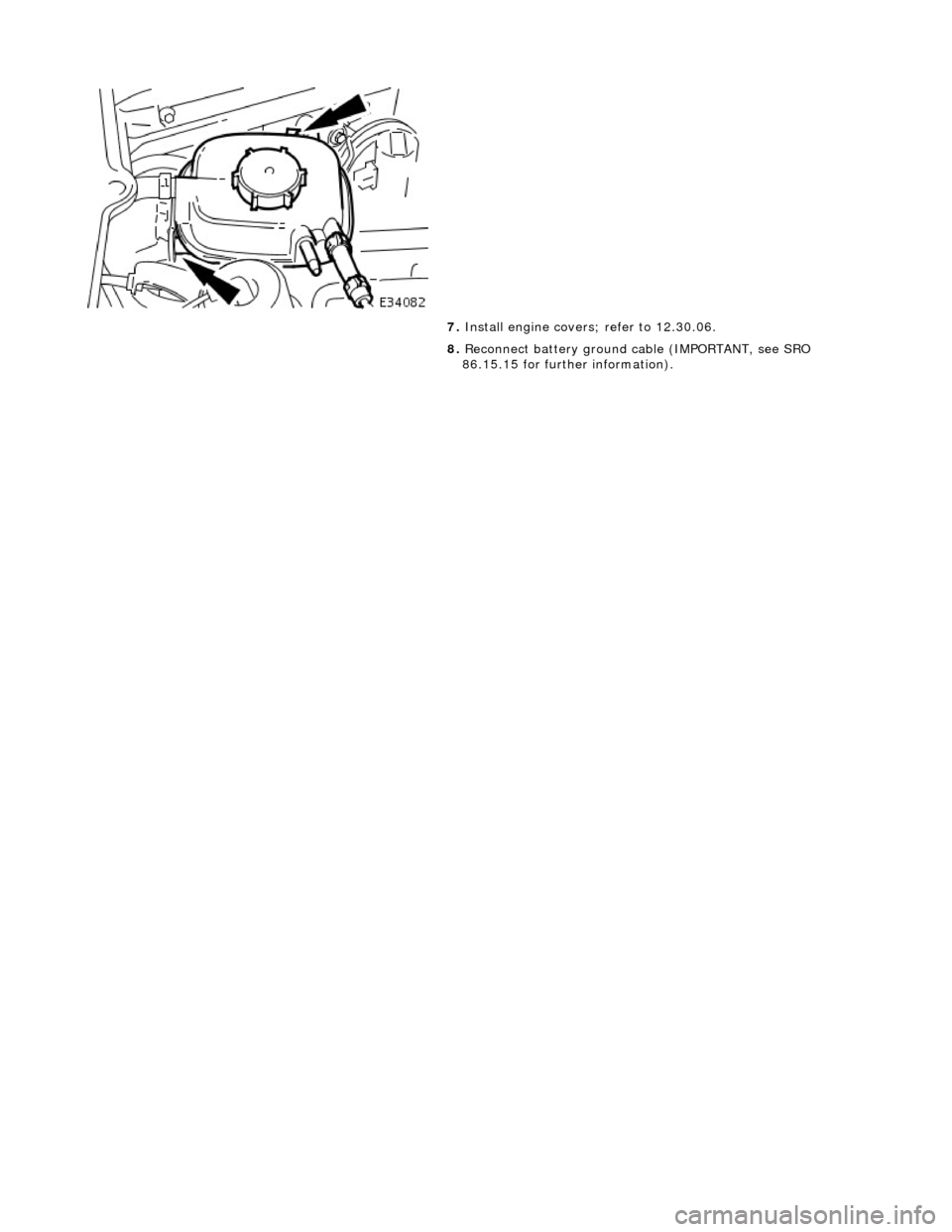
7.
Instal
l engine covers
; refer to 12.30.06.
8. Reconnect battery ground cable (IMPORTANT, see SRO
86.15.15 for further information).
Page 1237 of 2490
E
lectronic Engine Controls -
Catalyst Monitor Sensor LH
Re
moval and Installation
General Equipment
Remov
al
Installation
Snap
-on tool S6176
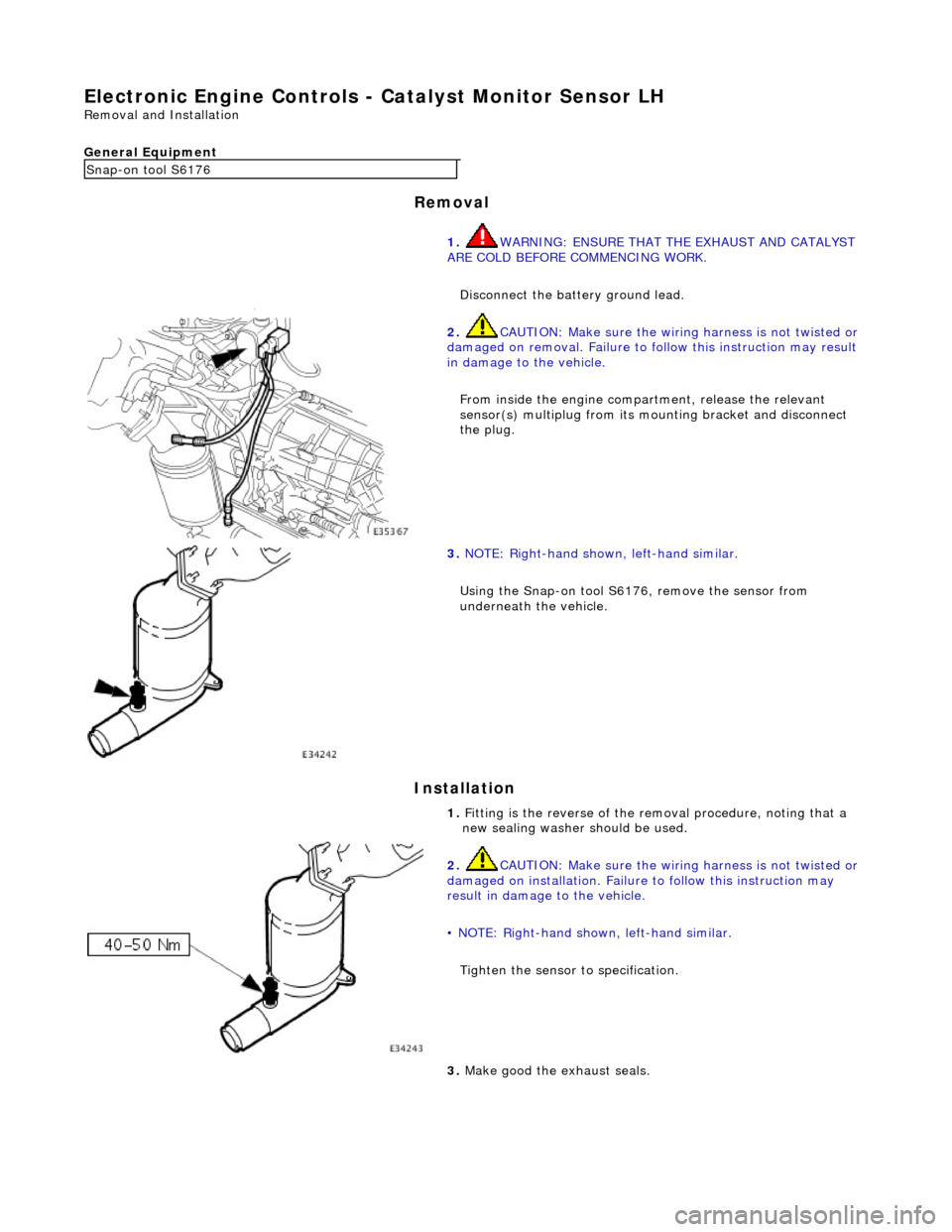
1. WARNING: ENSURE THAT THE EXHAUST AND CATALYST
ARE COLD BEFORE COMMENCING WORK.
Disconnect the battery ground lead.
2. CAUTI
ON: Make sure the wiring harness is not twisted or
damaged on removal. Failure to fo llow this instruction may result
in damage to the vehicle.
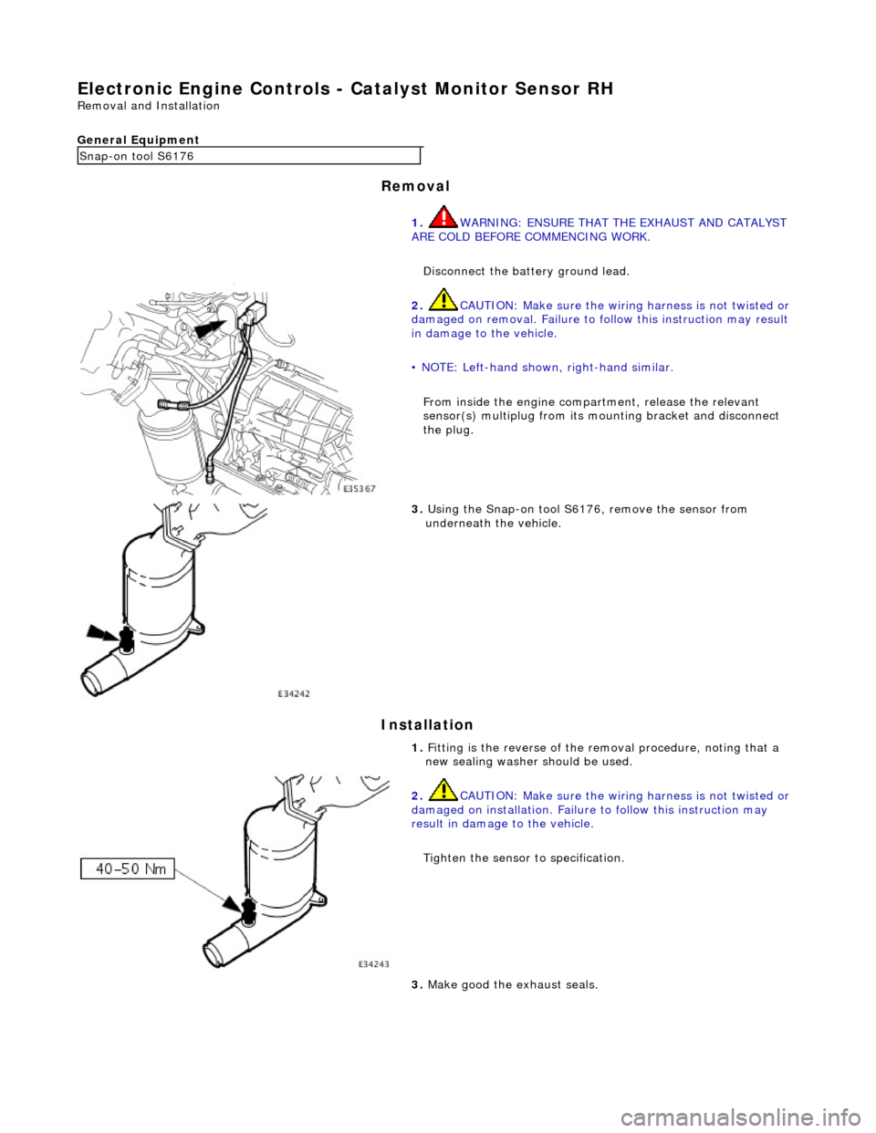
From inside the engine compartment, release the relevant
sensor(s) multiplug from its mounting bracket and disconnect
the plug.
3. NOTE
: Right-hand shown, left-hand similar.
Using the Snap-on tool S6176, remove the sensor from
underneath the vehicle.
1. Fitting is the reverse of the removal procedure, noting that a
new sealing washer should be used.
2. CAUTI
ON: Make sure the wiring harness is not twisted or
damaged on installation. Failure to follow this instruction may
result in damage to the vehicle.
• NOTE: Right-hand shown, left-hand similar.
Tighten the sensor to specification.
3. Make good th
e exhaust seals.
Page 1238 of 2490
El
ectronic Engine Controls -
Catalyst Monitor Sensor RH
Remo
val and Installation
General Equipment
Remov a
l
Installation
Snap -
on tool S6176
1. WARNING: ENSURE THAT THE EXHAUST AND CATALYST
ARE COLD BEFORE COMMENCING WORK.
Disconnect the battery ground lead.
2. CAUTIO
N: Make sure the wiring harness is not twisted or
damaged on removal. Failure to fo llow this instruction may result
in damage to the vehicle.
• NOTE: Left-hand shown, right-hand similar.
From inside the engine compartment, release the relevant
sensor(s) multiplug from its mounting bracket and disconnect
the plug.
3. Us
ing the Snap-on tool S6176, remove the sensor from
underneath the vehicle.
1. Fitting is the reverse of the removal procedure, noting that a
new sealing washer should be used.
2. CAUTI
O
N: Make sure the wiring harness is not twisted or
damaged on installation. Failure to follow this instruction may
result in damage to the vehicle.
Tighten the sensor to specification.
3. Make good th e exh
aust seals.
Page 1239 of 2490
E
lectronic Engine Controls - Cr
ankshaft Position (CKP) Sensor
Re
moval and Installation
Remov
al
1.
Disc
onnect battery ground cable (IMPORTANT, see SRO
86.15.19 for further information).
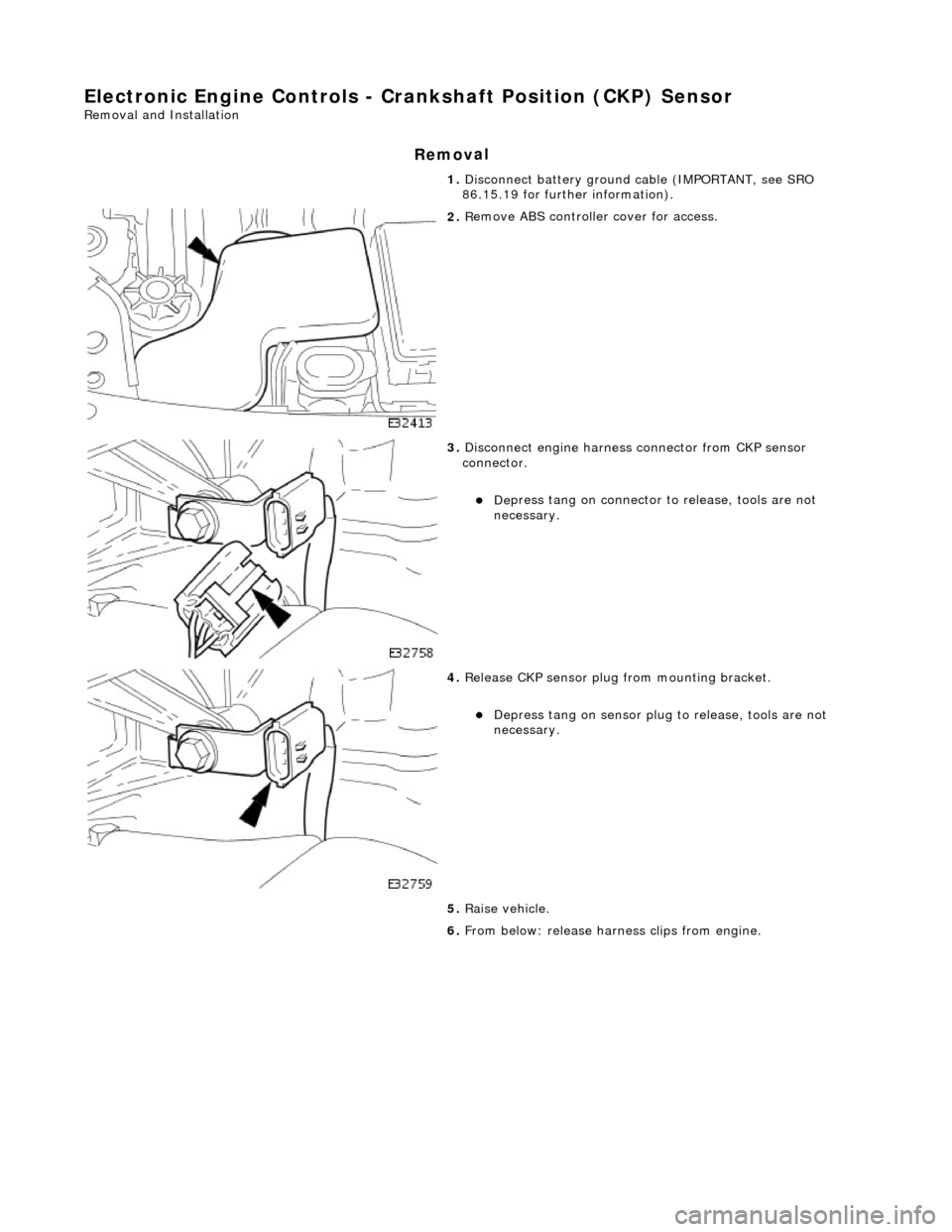
2. R
emove ABS controller cover for access.
3. Di
sconnect engine harness connector from CKP sensor
connector.
De
press tang on connector to release, tools are not
necessary.
4. Re
lease CKP sensor plug from mounting bracket.
Depress tan
g on sensor plug
to release, tools are not
necessary.
5. Raise vehicle.
6. From below: release harn ess clips from engine.
Page 1240 of 2490

In
stallation
7.
Re
move crankshaft position sensor.
R
e
move fixing.
Re
mo
ve sensor.
R
e
tain harness clips
1. Installation
is a reversal
of the removal procedure.