vin JAGUAR X308 1998 2.G Workshop Manual
[x] Cancel search | Manufacturer: JAGUAR, Model Year: 1998, Model line: X308, Model: JAGUAR X308 1998 2.GPages: 2490, PDF Size: 69.81 MB
Page 2207 of 2490

12. Pass free end of cheese wire through penetration and install
second cutting handle.
13. WARNING: When removing the rear window glass,
personal protection must be worn. Failure to follow this
instruction may result in personal injury.
• CAUTIONS:
Make sure the ch eese wire cannot contact the paintwork
while the the rear window glass ad hesive is being cut. Failure to
follow this instruction may result in damage to the vehicle.
When cutting, do not allow ch eese wire to contact edge of
window glass as this will crack the window glass.
• NOTE: Apply cutting lubricant to the cheese wire frequently
through out the cutting process.
With assistance and exercising care to avoid damaging the
paintwork, cut around the re ar window glass commencing
upwards and along the top.
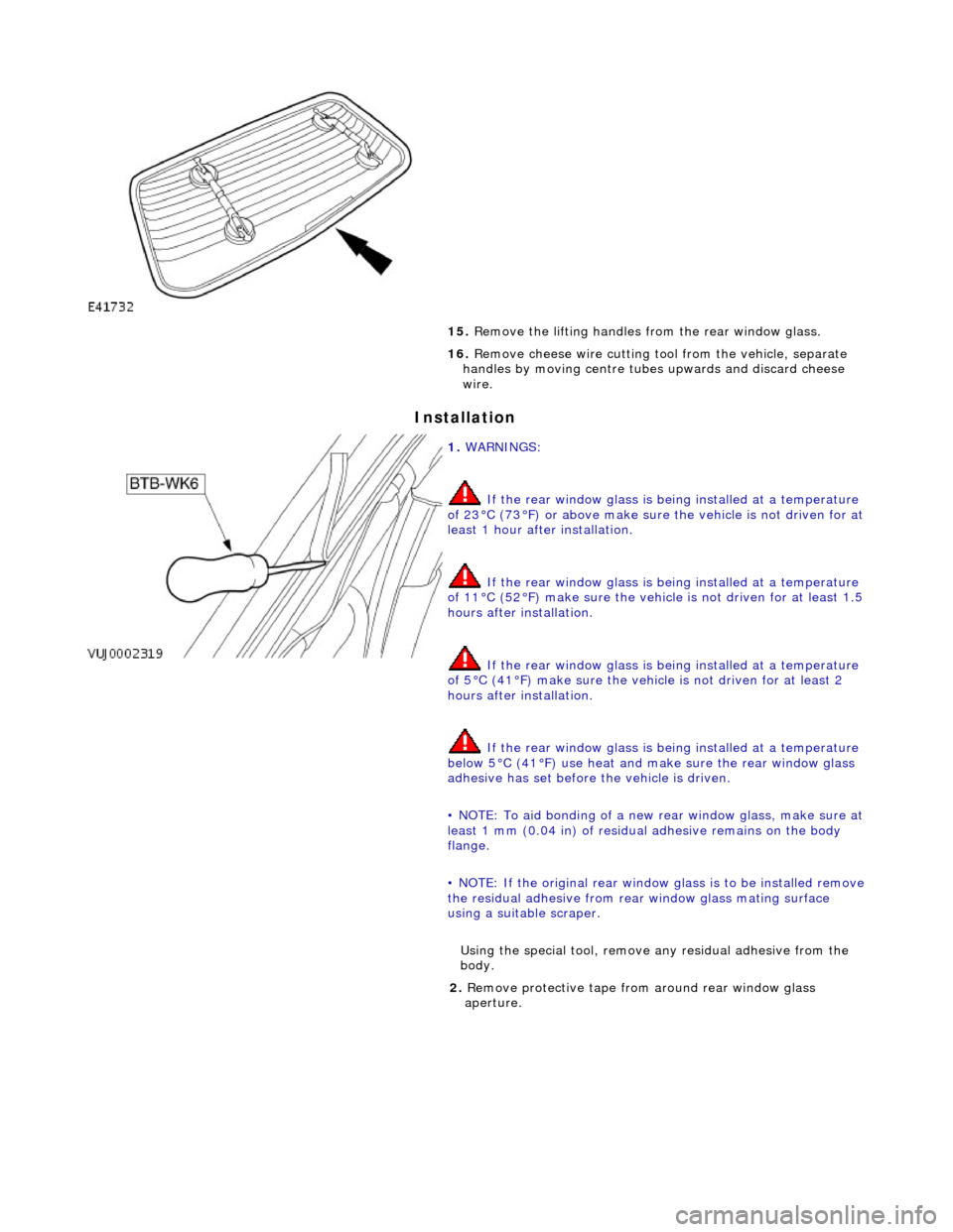
14. Install the lifting handles to the windshield glass, and with
assistance carefully remove th e rear window glass from the
vehicle.
Page 2208 of 2490
Installation
15. Remove the lifting handles from the rear window glass.
16. Remove cheese wire cutting tool from the vehicle, separate
handles by moving centre tubes upwards and discard cheese
wire.
1. WARNINGS:
If the rear window glass is being installed at a temperature
of 23°C (73°F) or above make sure the vehicle is not driven for at
least 1 hour after installation.
If the rear window glass is being installed at a temperature
of 11°C (52°F) make sure the vehicl e is not driven for at least 1.5
hours after installation.
If the rear window glass is being installed at a temperature
of 5°C (41°F) make su re the vehicle is not driven for at least 2
hours after installation.
If the rear window glass is being installed at a temperature
below 5°C (41°F) use heat and ma ke sure the rear window glass
adhesive has set before the vehicle is driven.
• NOTE: To aid bonding of a new re ar window glass, make sure at
least 1 mm (0.04 in) of residual adhesive remains on the body
flange.
• NOTE: If the original rear window glass is to be installed remove
the residual adhesive from rear window glass mating surface
using a suitable scraper.
Using the special tool, remove any residual adhe sive from the
body.
2. Remove protective tape from around rear window glass
aperture.
Page 2214 of 2490

Cut a suitable length of cheese wire and pass one end
through handle tube and locating aperture.
Move cutting handle central tube downwards to secure
cheese wire.
12. Using a suitable long bladed tool, penetrate Betaseal
approximately 150mm from the top of one A pillar.
13. Pass free end of cheese wire through penetration and install
second cutting handle.
14. WARNING: When removing the windshield glass,
personal protection must be worn. Failure to follow this
instruction may result in personal injury.
• CAUTIONS:
Make sure the ch eese wire cannot contact the paintwork
while the the windshield adhesive is being cut. Failure to follow
this instruction may result in damage to the vehicle.
Make sure the cheese wire cannot contact the instrument
panel while the the windshield adhesive is being cut. Failure to
follow this instruction may result in damage to the vehicle.
Make sure the cheese wire passes the Vehicle Identification
Number (VIN) plate on the correct side. Failure to follow this
instruction may result in damage to the component.
When cutting, do not allow ch eese wire to contact edge of
windshield glass as this will crack the windshield glass.
• NOTE: Apply cutting lubricant to the cheese wire frequently
through out the cutting process.
With assistance and exercising care at the corners to avoid
damaging paintwork, cut around the windshield glass
Page 2328 of 2490
Roof Opening Panel - Roof Opening Panel
Description and Operation
General Description
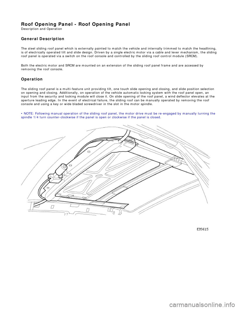
The steel sliding roof panel which is externally painted to ma tch the vehicle and internally trimmed to match the headlining,
is of electrically operated tilt and slide design. Driven by a single electric motor via a cable and lever mechanism, the slidi ng
roof panel is operated via a switch on the roof console and controlled by the sliding roof control module (SRCM).
Both the electric motor and SRCM are mounted on an extens ion of the sliding roof panel frame and are accessed by
removing the roof console.
Operation
The sliding roof panel is a multi-feature unit providing tilt, one touch slide opening and closing, and slide position selectio n
on opening and closing. Additi onally, on operation of the vehicle automatic locking system with the roof panel open, an
input from the security and lockin g module will close it. On slide opening of the roof panel, a wind deflector elevates at the
aperture leading edge. In the event of electrical failure, the sliding roof can be manually operated by removing the roof
console and using a key or wide bladed scre wdriver in the slot in the motor spindle.
• NOTE: Following manual operation of the sliding roof panel, the motor drive must be re-engaged by manually turning the
spindle 1/4 turn counter-clockwise if the panel is open or clockwise if the panel is closed.
Page 2332 of 2490
Roof Opening Panel - Roof Opening Panel Frame
Removal and Installation
Removal
1. Adjust front passenger seat fu lly rearwards and fully recline
seat squab.
2. Remove battery cover and disc onnect ground cable from
battery terminal. Refer to 86.15.19.
3. Remove sliding roof flange finisher. Refer to 76.82.23.
4. Remove sliding roof trim panel. Refer to 76.82.19.
5. Remove grab handles. Refer to 501-05.
6. Remove roof console. Refer to 76.13.69.90.
7. Remove sun visors. Refer to 501-05.
8. Remove cantrail/upper A post trims. Refer to 76.13.20.
9. Remove rear quarter trim s. Refer to 76.13.13.
10. Remove front half headlining for access. refer to 76.64.15.90.
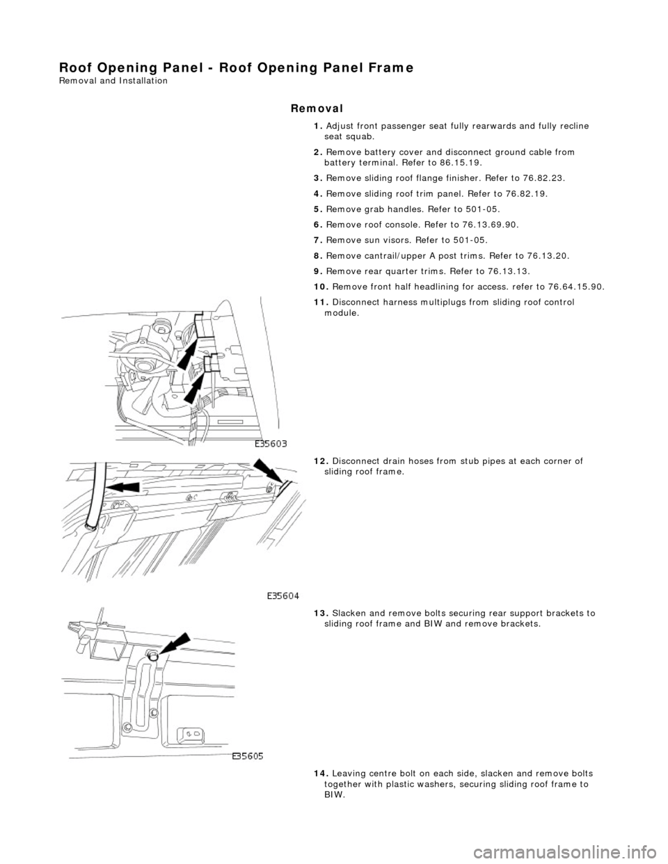
11. Disconnect harness multiplugs from sliding roof control
module.
12. Disconnect drain hoses from stub pipes at each corner of
sliding roof frame.
13. Slacken and remove bolts securi ng rear support brackets to
sliding roof frame and BIW and remove brackets.
14. Leaving centre bolt on each side, slacken and remove bolts
together with plastic washers, securing sliding roof frame to
BIW.
Page 2360 of 2490
Safety Belt System - Safety Belt System
Description and Operation
Front Seat Belts
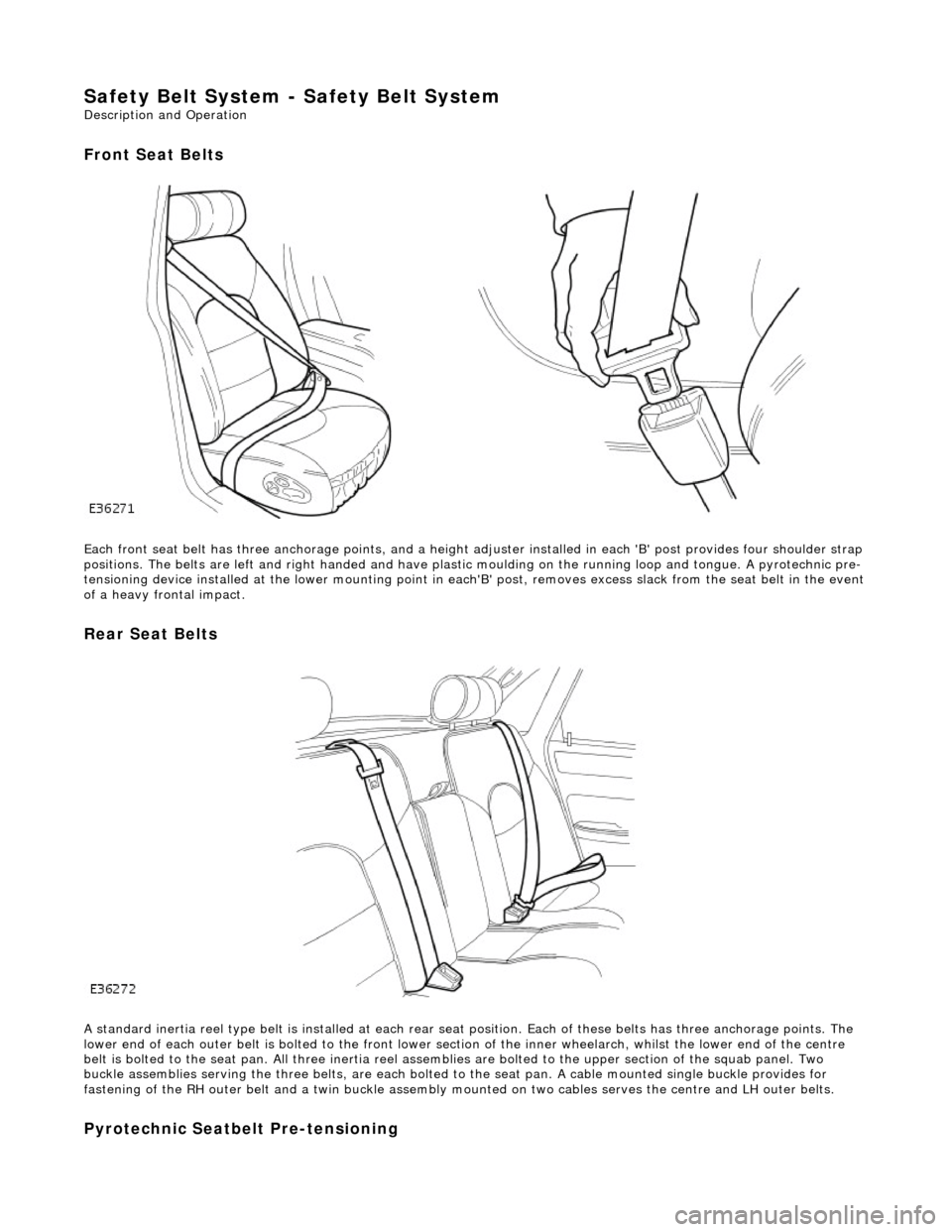
Each front seat belt has three anchorage points, and a height adjuster installed in each 'B' post provides four shoulder strap
positions. The belts are left and right ha nded and have plastic moulding on the r unning loop and tongue. A pyrotechnic pre-
tensioning device installed at the lower mounting point in each 'B' post, removes excess slack from the seat belt in the event
of a heavy frontal impact.
Rear Seat Belts
A standard inertia reel type belt is installed at each rear seat position. Each of these belts has three anchorage points. The
lower end of each outer belt is bolted to the front lower section of the inner wheelarch, whilst the lower end of the centre
belt is bolted to the seat pan. All thr ee inertia reel assemblies are bolted to the upper section of the squab panel. Two
buckle assemblies serving the three belts, are each bolted to the seat pan. A cable mounted single buckle provides for
fastening of the RH outer belt and a twin buckle assembly mounted on two cables serves the centre and LH outer belts.
Pyrotechnic Seatbelt Pre-tensioning
Page 2361 of 2490

A pyrotechnic front seat belt pre-tensioning device with independent el ectronic sensing and retractor unit is installed at the
base of each 'B' post. In the event of se vere frontal impact, this provides additional front occupant protection by removing
any excess slack from the seat be lt. Seat belt pre-tensioning activates when a frontal impact of sufficient force occurs within
30 degrees of vehicle center line. Under such an impact, el ectronic sensors in the retractor unit fire, igniting the pre-
tensioner gas generator. The ga s generator initiates a chemical reaction, producing gases under pressure. Gas pressure
drives the piston/cable up a tube, rotating the retractor sp indle and removing excess slack from the seat belt. When the
pre-tensioner unit has been activated, the seat belt will lock and cannot be retracted or pulled from the reel.If a seat belt
pre-tensioner activates, a small quantity (less than 1 liter) of gas is produced containing nitrogen, oxygen and water vapor.
Page 2371 of 2490
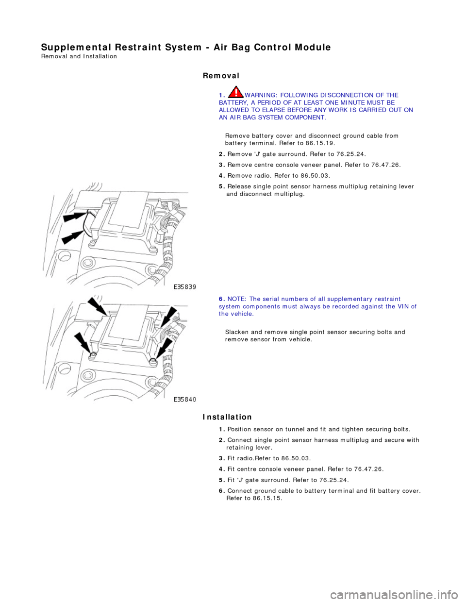
Supplemental Restraint System - Air Bag Control Module
Removal and Installation
Removal
Installation
1.
WARNING: FOLLOWING DISCONNECTION OF THE
BATTERY, A PERIOD OF AT LEAST ONE MINUTE MUST BE
ALLOWED TO ELAPSE BEFORE ANY WORK IS CARRIED OUT ON
AN AIR BAG SYSTEM COMPONENT.
Remove battery cover and disc onnect ground cable from
battery terminal. Refer to 86.15.19.
2. Remove 'J' gate surroun d. Refer to 76.25.24.
3. Remove centre console veneer panel. Refer to 76.47.26.
4. Remove radio. Re fer to 86.50.03.
5. Release single point sensor ha rness multiplug retaining lever
and disconnect multiplug.
6. NOTE: The serial num bers of all supplementary restraint
system components must always be recorded against the VIN of
the vehicle.
Slacken and remove single point sensor securing bolts and
remove sensor from vehicle.
1. Position sensor on tunnel and fit and tighten securing bolts.
2. Connect single point sensor harn ess multiplug and secure with
retaining lever.
3. Fit radio.Refer to 86.50.03.
4. Fit centre console veneer panel. Refer to 76.47.26.
5. Fit 'J' gate surround. Refer to 76.25.24.
6. Connect ground cable to battery terminal and fit battery cover.
Refer to 86.15.15.
Page 2375 of 2490

Installation
• NOTE: The serial numbers of all supplementary restrain t system components must always be recorded against the VIN of
the vehicle.
6. Withdraw air bag module and remove from vehicle.
7. Slacken, remove and discard two bolts securing air bag tether
bracket to air bag module.
1. Position air bag module on teth er bracket and fit and tighten
two new securing bolts.
2. Position air bag module and deployment door mounting
bracket in fascia.
3. Fit and tighten four new nuts and washers securing air bag
Page 2381 of 2490
The body is pre-treated to ensure high resistance to corrosion and stone chip dama ge. Prior to the first major pre-treatment process, the body shell is high-pressure washed to remove any metal dust and residual oil.
The first major pre-treatment process consists of phosphate and electro-paint deposition, which together with zinc coating,
forms the basis of the corrosion protection. This process includes high pressure knock-off, alkali de-greasing, zinc phosphate
conversion of body steel (dissolving iron and coating with zinc phosphate crystals), trivalent chrome rinsing and
demineralized water rinsing, seal ing all chemicals and impurities.
Both dip and spray techniques are employed and the bodies are submerged to the waistline during the first and third rinses
of the main phosphate clean. Chemical strengths and soluti on temperatures are continuously monitored and accurately
controlled throughout the process.
An 80% water primer is then cathodic elec tro-deposition applied to the thoroughly cleansed bodies in a uniform 'sag-free'
film 18 to 32 micron thick. Optimum durabi lity of the electroprimer is achieved by finally curing in a stoving oven at 165 °C
for a period of 20 minutes.
All underbody seams of the fully primed bo dies are then manually sealed, to prevent water and dust ingress into the vehicle
and to enhance corrosion protection.
An 800 to 1000 g/m2 PVC coating is semi-automatic airless sp ray applied to the underside of the main floor panels, trunk
floor and rear wheel arches (ref. illustration above).
The upper panels of primed and external ly sealed bodyshells are next lightly scuffed to remove imperfections and a PVC
coating is applied to all internal seams by an airless spray technique. A PVC bead seal is also applied to the doors, hood and
trunk clinch joints.
Following anti-corrosion, sealing and primin g treatment, the bodies enter the first stage of 'cosmetic' painting. This consists
of the application of two coats of a highly chip resistant po lyester surfacer, employing high voltage electrostatic 'spinning
bells', to achieve a final film thickness of 35 to 50 micron. Between surfacer coats, a polyurethane coat is automatically
applied to the sills to impart even greater resistance to stone chipping.
All interior panels are then painted us ing a color keyed sealer, wet-on-wet wi th a surfacer material, after which the
bodyshells are stoved at 160 °C for a period of 20 minutes. Further protection agai nst corrosion is provided by a medium
solids black pigmented wax which is airless spray applied to vehicle undersides.
Wax Injected Box Sections
Critical body box-sections are si milarly protected by spray injecting a high solids wax. This is then re-flowed at 70 to 90 °C
to achieve optimum seam/joint penetratio n and form a resilient and durable internal coating (ref. illustration above).
After full wet sanding, rinsing and drying to provide a good su bstrate, a color-keyed semi-matt sealer co at is applied using
electrostatic bells to achieve a film build of 25 to 35 micron . The bodies are then stoved for a further 20 minutes at a
temperature of 145 °C and subjected to a local 'seek-and-find' de -nib operation prior to the final two coat process. The final
top coat finish is achieved by using poly ester base coat colors and an acrylic sag resistant clear coat. This clear over base
(COB) process produces a high gloss, durabl e paint finish with a film thickness of 50 to 65 micron, which is finally cured at a
temperature of 135°C for 20 minutes.
The Munsell three dimensional system of color management is em ployed to achieve highly accurate control of vehicle colors.
This system ensures that paint pigmentations are accurately maintained and facilitates vigorous final checking of finished
vehicles for color match. The hu e of individual panels such as trunk lids, doors and hoods is in some instances adjusted to
offset the effects of differing light angles. Where applicable, coachlines are manually applied and radiant heat cured on the
completed and valeted vehicle prior to hand spray applic ation of a protective wax coat.
Introduction
All repairs, whether structural or cosmetic must return the vehicle to the original manufactured condition with regard to
occupant safety, dimensional accuracy, fi nish and corrosion protection, and ensure continuation of the Paint Surface and
Corrosion warranty where applicable.
Similarly, repaired vehicles must be fu lly checked, and where appropriate reset, with regard to steering, suspension,
braking, and occupant restraint systems.