JAGUAR X308 1998 2.G Workshop Manual
X308 1998 2.G
JAGUAR
JAGUAR
https://www.carmanualsonline.info/img/21/7640/w960_7640-0.png
JAGUAR X308 1998 2.G Workshop Manual
Trending: battery charger, exhaust, ECU, seat memory, sunroof, error, parking brake ORDER BY 20
Page 2391 of 2490
ZINC COATED PANELS
Description
Approximately 70% of the 'body in white' (BIW) mass is made up of zinc coated panels.
• NOTE: To maintain the protective qualities of the zinc trea tment, repairs to any damaged coated area must be made as
soon as possible after the damage has occurred.
All exterior skin panels, with the exceptio n of the roof, are double side zinc plated and this coating (nominally 7,5 microns)
provides two way corrosion protection. Should the outer layer of paint become chipped with the zinc coating remain intact,
the zinc will oxidize on contact with air and being impermeable, this coat of oxidation will prevent corrosion damage of the
base metal. If the outer layer of paint and the zinc coating become damaged, the zinc rather than the base metal will react
with the air and 'sacrifice' itself to corrosion as a 'sacrificial anode'.
Welding Preparation
Contamination of the weld with resultant reduction in joint st rength increase and increased electrode tip dressing frequency
will occur zinc coating is not removed. In exceptional cases where the zinc coating must remain intact, the tip pressure and
welding current should be increased by 10 to 20%.
Where 'resistance spot welding' is employed, the zinc coatin g should be lightly abraded away on the mating surfaces and
those in contact with the electrode tips. Do not remove more zinc coating than is absolutely necessary.
Before welding, a weld-through primer or inter-weld sealer should be applied, as detailed in the Body Sealing and
Preservation manual.
Where MIG welding is used as an alternativ e to resistance spot welding for plug and butt welds or due to limited access, the
problems caused by the presence of zinc coating are much the same, with the added complication of increased weld spatter
and nozzle contamination.
Body Fillers
Conventional polyester fillers do not adhere satisfactorily to zinc plated panels, it is ther efore important that only those
products specifically designed for this application are used and the manufacturer's recommendations are followed.
Refinishing
Use only those products approved by Jaguar Cars Ltd and exercise special care on zinc coated panels.
As replacement panels ar e supplied ready primed, the only bare metal that needs to be exposed are those areas prepared
for welding etc, as decribed in 'Welding Preparation. Where any part of a panel is dressed back to the bare surface, it should
be treated with a zinc rich primer compatible with the paint application system.
GENERAL PREPARATION OF PANELS
Removal of Panels and Welds
• NOTE: Where other components must be removed for access, refer to the relevant manual section for guidance. This is
particularly important where steerin g, braking, suspension, electrical and safety systems are affected.
Expose all resistance spot welds, using a ro tary wire brush fitted to an air drill or a hand held wire brush on those that are
not clearly visible (1).
WARNING: DO NOT BURN UNDERSEAL OFF. USE A 'HOT KNIFE' OR SUITABLE SOLVENT.
Cut out spot welds using a Zipcutter or Roto-Bor (2). At this point it may be necessary to cut out the bulk of the panel using
Page 2392 of 2490
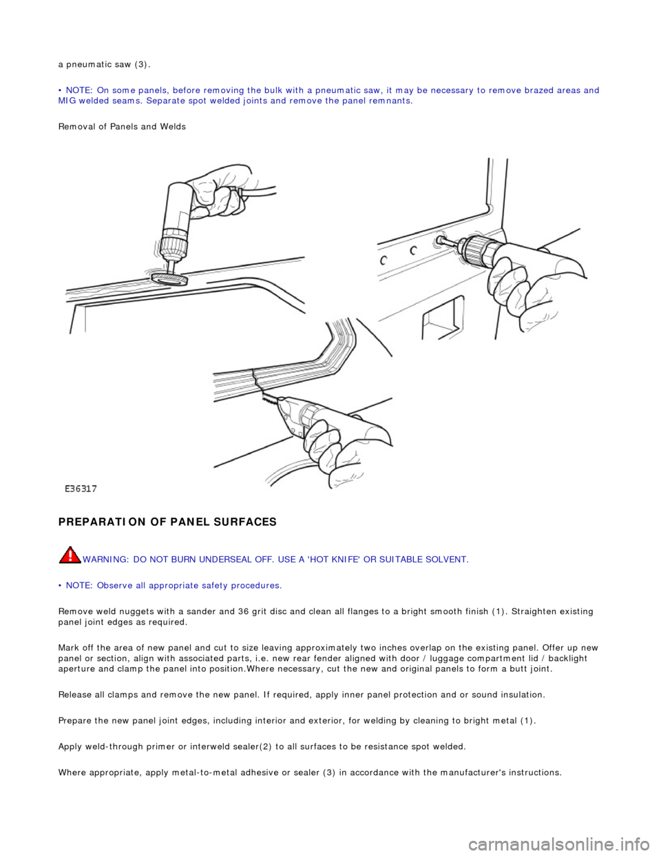
a pneumatic saw (3).
• NOTE: On some panels, before removing the bulk with a pneumatic saw, it may be necessary to remove brazed areas and
MIG welded seams. Separate spot welded joints and remove the panel remnants.
Removal of Panels and Welds
PREPARATION OF PANEL SURFACES
WARNING: DO NOT BURN UNDERSEAL OFF. USE A 'HOT KNIFE' OR SUITABLE SOLVENT.
• NOTE: Observe all appropriate safety procedures.
Remove weld nuggets with a sander and 36 gr it disc and clean all flanges to a bright smooth finish (1). Straighten existing
panel joint edges as required.
Mark off the area of new panel and cut to size leaving approxim ately two inches overlap on the existing panel. Offer up new
panel or section, align with associated pa rts, i.e. new rear fender aligned with door / luggage compartment lid / backlight
aperture and clamp the panel into positi on.Where necessary, cut the new and orig inal panels to form a butt joint.
Release all clamps and remove the new panel. If required, apply inner panel protection and or sound insulation.
Prepare the new panel joint edges, including interior and exterior, for welding by cleaning to bright metal (1).
Apply weld-through primer or in terweld sealer(2) to all surfaces to be resistance spot welded.
Where appropriate, apply metal- to-metal adhesive or sealer (3) in accordance with the manufacturer's instructions.
Page 2393 of 2490
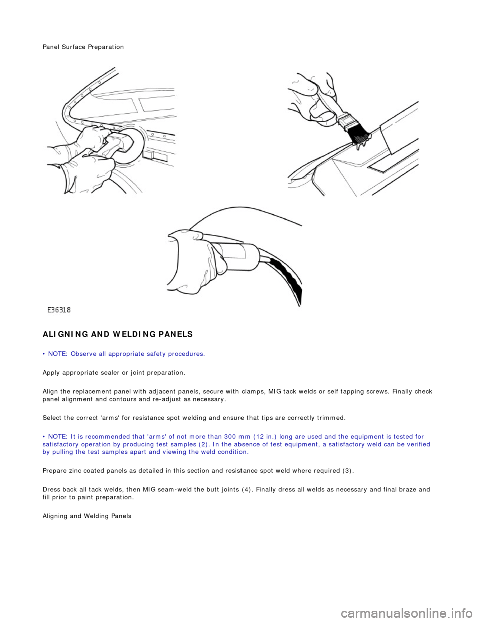
Panel Surface Preparation
ALIGNING AND WELDING PANELS
• NOTE: Observe all appropriate safety procedures.
Apply appropriate sealer or joint preparation.
Align the replacement panel with adjacent panels, secure with clamps, MIG tack welds or self tapping screws. Finally check
panel alignment and contours and re-adjust as necessary.
Select the correct 'arms' for resistance spot welding and ensure that tips are correctly trimmed.
• NOTE: It is recommended that 'arms' of not more than 300 mm (12 in.) long ar e used and the equipment is tested for
satisfactory operation by producing test samples (2). In the ab sence of test equipment, a satisfactory weld can be verified
by pulling the test sa mples apart and viewing the weld condition.
Prepare zinc coated panels as detailed in this section and resistance spot weld where required (3).
Dress back all tack welds, then MIG seam-weld the butt joints (4). Finally dress all welds as necessary and final braze and
fill prior to paint preparation.
Ali
gning and Welding Panels
Page 2394 of 2490
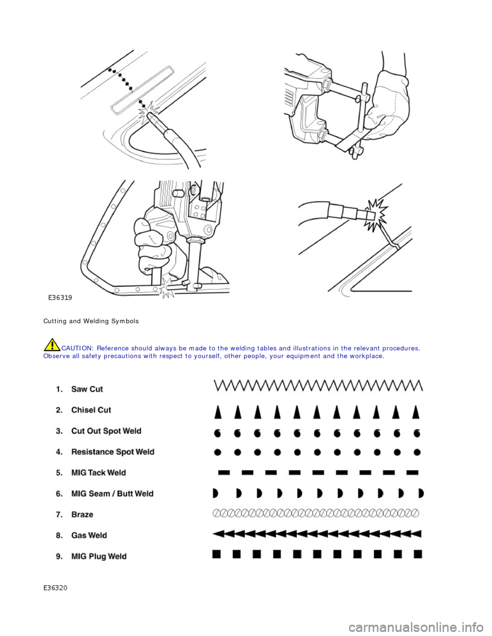
Cutting and Welding Symbols CAUTION: Reference should always be made to the welding tables and illust rations in the relevant procedures.
Observe all safety precautions with respect to yourself, ot her people, your equipment and the workplace.
Page 2395 of 2490
CAVITY WAX INJECTION - APPROVED ADHESIVES, SEALERS AND BODY PROTECTION
SYSTEMS
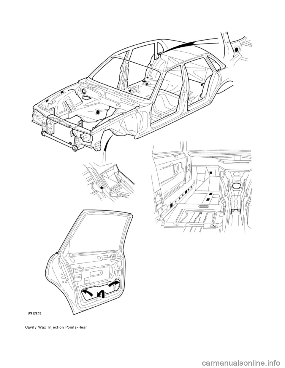
• NOTE: Cavity wax processes should only be applied on completion of all other refinishing and protection procedures.
Cavity Wax Injection Points - Front
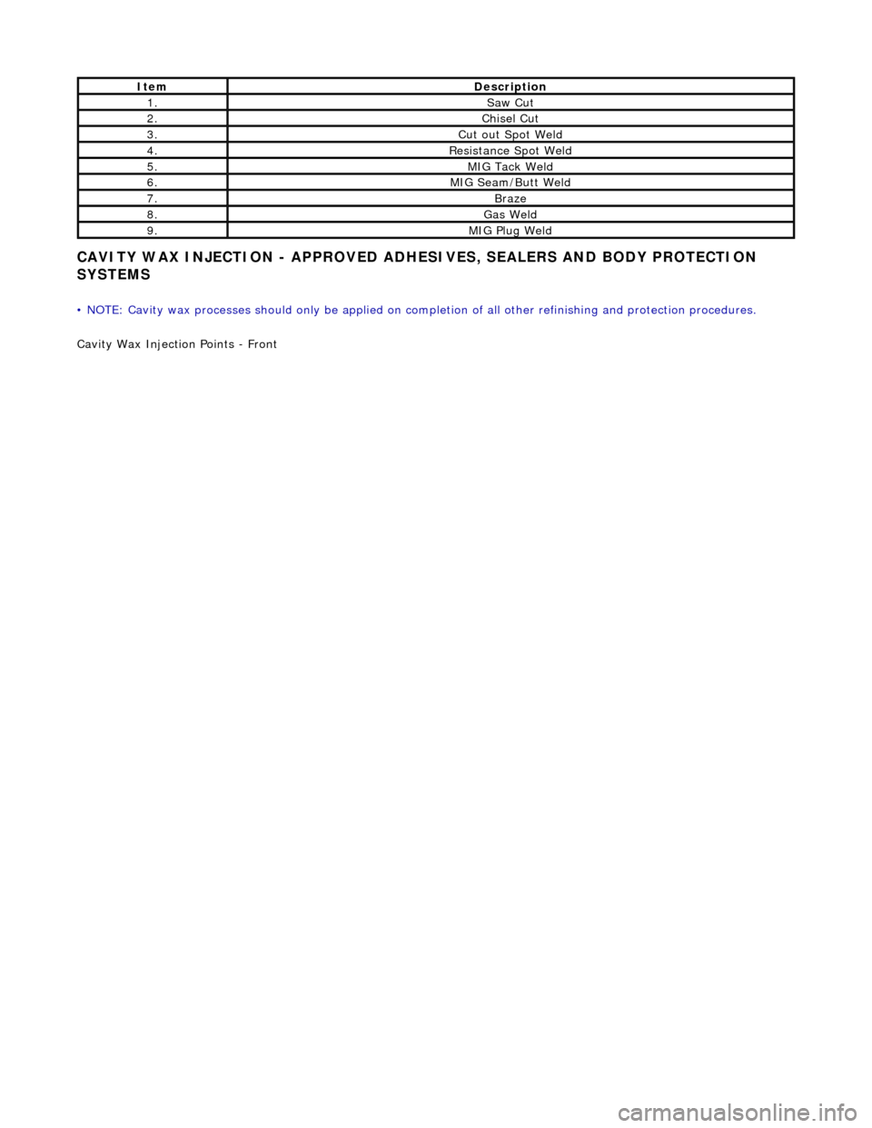
ItemDescription
1.Saw Cut
2.Chisel Cut
3.Cut out Spot Weld
4.Resistance Spot Weld
5.MIG Tack Weld
6.MIG Seam/Butt Weld
7.Braze
8.Gas Weld
9.MIG Plug Weld
Page 2396 of 2490
Cavity Wax Injection Points-Rear
Page 2397 of 2490
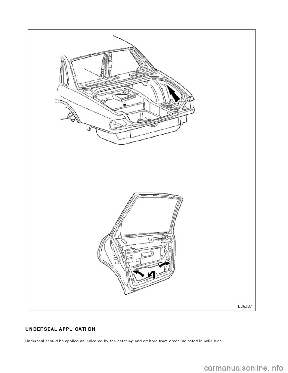
UNDERSEAL APPLICATION
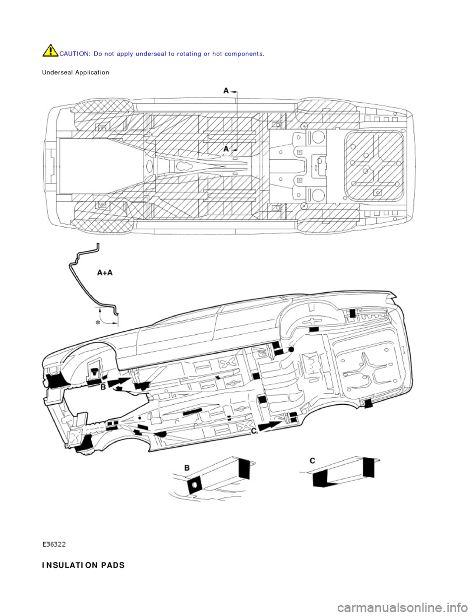
Underseal should be applied as indicated by the hatching and omitted fro m areas indicated in solid black.
Page 2398 of 2490
CAUTION: Do not apply underseal to rotating or hot components.
Underseal Application
INSULATION PADS
Page 2399 of 2490
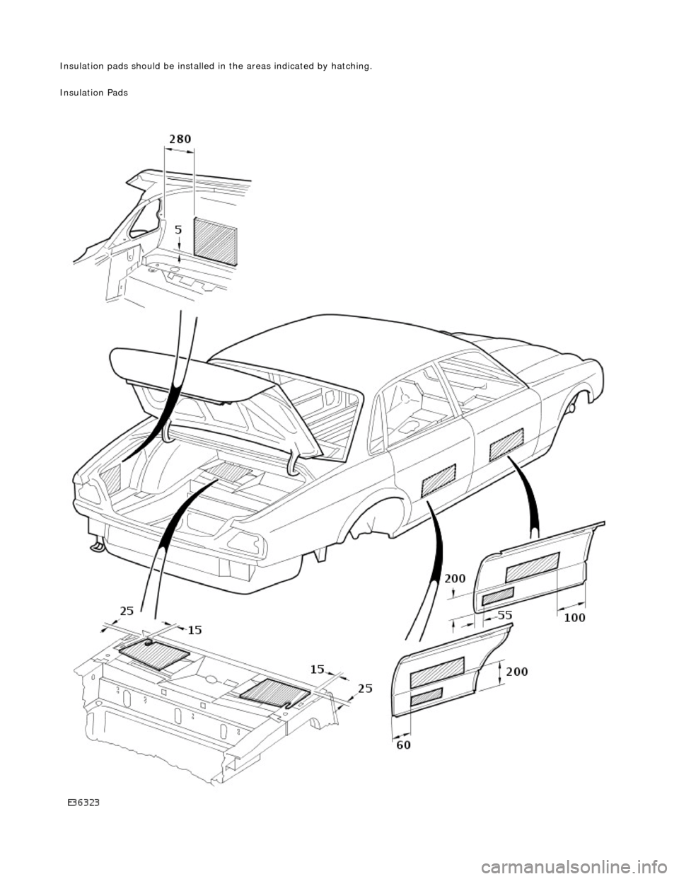
Insulation pads should be installed in the areas indicated by hatching.
Insulation Pads
Page 2400 of 2490
Trending: Electronic engine controls, rear bumper, fuel filter, air conditioning, transmission oil, refilling coolant system, Seat


