chain JAGUAR X308 1998 2.G Owner's Manual
[x] Cancel search | Manufacturer: JAGUAR, Model Year: 1998, Model line: X308, Model: JAGUAR X308 1998 2.GPages: 2490, PDF Size: 69.81 MB
Page 584 of 2490

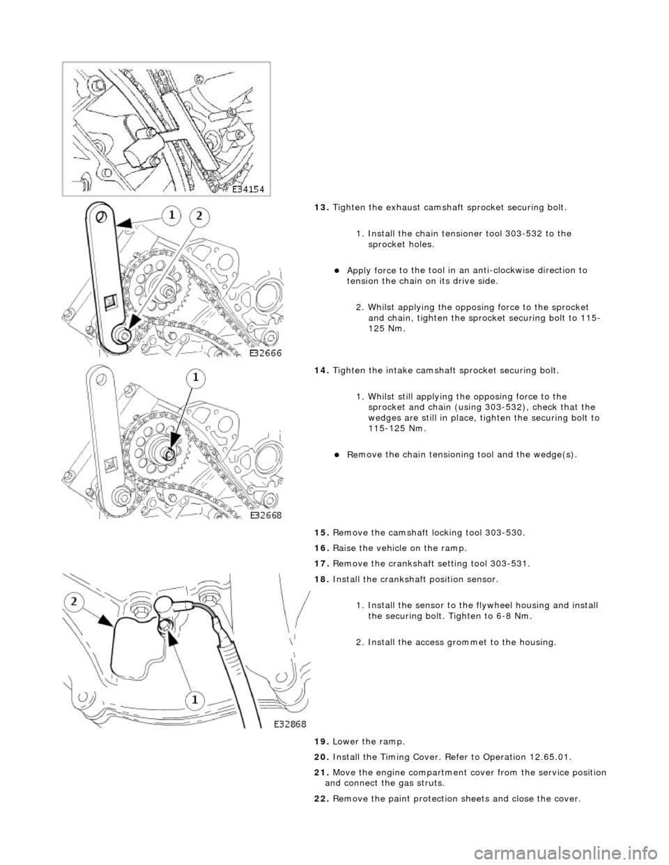
13. Tigh
ten the exhaust camshaft
sprocket securing bolt.
1. Install the chain tensioner tool 303-532 to the sprocket holes.
пЃ¬Appl y force
to the tool in an
anti-clockwise direction to
tension the chain on its drive side.
2. Whilst applying the opposing force to the sprocket and chain, tighten the sprock et securing bolt to 115-
125 Nm.
14 .
Tigh
ten the intake camshaft
sprocket securing bolt.
1. Whilst still applying the opposing force to the
sprocket and chain (using 303-532), check that the
wedges are still in place, ti ghten the securing bolt to
115-125 Nm.
пЃ¬R e
move the chain tensioning
tool and the wedge(s).
15. Remove the camshaft locking tool 303-530.
16. Raise the vehicle on the ramp.
17. Remove the crankshaft setting tool 303-531.
18 . Inst
all the crankshaft position sensor.
1. Install the sensor to the flywheel housing and install
the securing bolt. Tighten to 6-8 Nm.
2. Install the access grommet to the housing.
19. Lower the ramp.
20. Install the Timing Cover. Refer to Operation 12.65.01.
21. Move the engine compartment cover from the service position
and connect the gas struts.
22. Remove the paint protection sheets and close the cover.
Page 586 of 2490

Engine - Crankshaft Outer
Sprocket
In-v
ehic
le Repair
Remov
a
l
S
p
ecial Tool(s)
Camshaft setting
3
03-
530
T
i
ming chain tensioning
303-532
Wedges, primary ch ain
303-533
Cranksha
ft setting
303-531
1. Open the engine compartment and fit paintwork protection
sheets.
2. Set the engine compartment cover to the service access
position.
3. Disc
onnect the batt
ery ground cable.
пЃ¬Re
move the battery cover.
4. Remove the Timing Co ver. Refer to Operation 12.65.01 in this
Section.
5. Remove the VVT bush carrier.
1. Remove the three bolts which secure the carrier to the cylinder block.
Page 589 of 2490

I
nstallation
18
.
Remove the tensioner assembly.
1. Remove the tensioner.
2. Remove the tensioner back-plate.
19
.
Remove the chain tensioner blade.
1. Remove the pivot bolt which secures the tensioner blade.
2. Remove the tensioner blade.
20. Remove the chain from the VVT unit and from the crankshaft
sprocket.
21
.
If necessary, remove the sp rocket from the crankshaft.
пЃ¬No
te the orientation of the
sprocket relative to the
sprocket for the B-Bank drive (half a tooth out of line) and
remove the sprocket.
22. Clean and inspect all relevant components.
1. If removed previously, fit the sprocket to the crankshaft.
Page 590 of 2490

пЃ¬The
teeth of the A-Bank and the B-Bank sprockets on the
crankshaft must be out of phas e with each other. If they
are in-phase after fitting, remo ve the sprocket, turn it on
its vertical axis and refit it.
2. Fi
t the chain tensioning tool 303 - 532 to the exhaust camshaft
sprocket.
пЃ¬Re po
sition the sprocket (and
the VVT unit) for the most
advantageous position for use of the tool.
пЃ¬R e
move the tool.
3. Re
fit the primary timing chain.
1. Fit the primary chain to position over the crankshaft sprocket and the VVT unit sprocket. There must be no
slack on the drive side of the primary chain and the
VVT unit must not be rotated on the camshaft.
4. Fit the primary chain tensioner
blade.
1. Position the tensioner blade to the cylinder block.
2. Fit the retaining / pivot bolt and tighten it to 12-16 Nm.
5. Refit the primary chain tensione r assembly. Refer to Operation
12.65.54 in this Section.
пЃ¬U s
e a wedge 303 - 533 (or two if required) between the
primary chain tensioner and te nsioner blade, to take up
the slack in the chain.
Page 591 of 2490

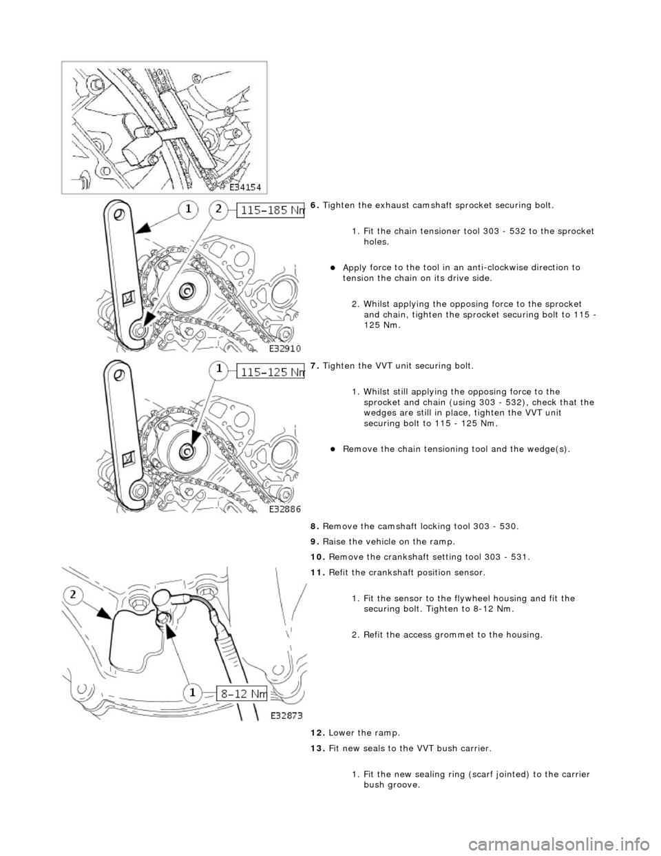
6. Tigh
ten the exhaust camshaft
sprocket securing bolt.
1. Fit the chain tensioner tool 303 - 532 to the sprocket holes.
пЃ¬Appl
y force to the tool in an
anti-clockwise direction to
tension the chain on its drive side.
2. Whilst applying the opposing force to the sprocket and chain, tighten the sprock et securing bolt to 115 -
125 Nm.
7. Tigh
ten the VVT unit securing bolt.
1. Whilst still applying the opposing force to the
sprocket and chain (using 303 - 532), check that the
wedges are still in place, tighten the VVT unit
securing bolt to 115 - 125 Nm.
пЃ¬R
emove the chain tensioning
tool and the wedge(s).
8. Remove the camshaft locking tool 303 - 530.
9. Raise the vehicle on the ramp.
10. Remove the crankshaft setting tool 303 - 531.
11
.
Refit the crankshaft position sensor.
1. Fit the sensor to the fl ywheel housing and fit the
securing bolt. Tighten to 8-12 Nm.
2. Refit the access grommet to the housing.
12. Lower the ramp.
13. Fit new seals to the VVT bush carrier.
1. Fit the new sealing ring (scarf jointed) to the carrier bush groove.
Page 611 of 2490

E
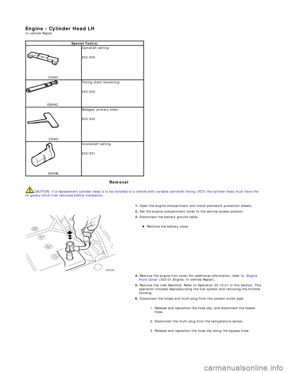
ngine - Cylinder Head LH
In-ve
hicle Repair
Remova
l
CAU
TION: If a replacement cylinder head is to be installed to a
vehicle with variable camshaft timing (VCT) the cylinder head m ust have the
oil gallery blind rivet removed before installation.
Spe
cial Tool(s)
Cams
haft setting
303-530
Ti
ming chain tensioning
303-532
Wedges, prim
ary chain
303-533
Cr
ankshaft setting
303-531
1.
Open the engine compartment and install paintwork protection sheets.
2. Set the engine compartment cover to the service access position.
3.
Disconnect the battery ground cable.
пЃ¬Re
move the battery cover.
4. Remove the engine fron cover.For additional information, refer to: Engine
Front Cover (303-01 Engi
ne, In-vehicle Repair).
5. Remove the Inlet Manifold. Refer to Operation 30.15.01 in this Section. This operation includes depressurising the fuel system and removing the throttle
housing.
6. Disconnect the hoses and multi-plug from the coolant outlet pipe.
1. Release and reposition the hose clip, and disconnect the heater hose.
2. Disconnect the multi-plug from the temperature sensor.
3. Release and reposition the hose clip along the bypass hose.
Page 614 of 2490

21. L
oosen the bolt which secures the VVT unit to the camshaft.
22. Remove the camshaft locking tool 303 - 530 (installed for previous
operation).
23 . R
emove the primary chain tensioner bolts.
24 . R
emove the tensioner assembly.
1. Remove the tensioner.
2. Remove the tens ioner back-plate.
25 . R
emove the primary chain tensioner blade.
1. Remove the pivot bolt which secures the tensioner blade.
2. Remove the tensioner blade.
26. Reposition the VVT unit along the cam journal to allow the chain to clear
the head casting.
пЃ¬Di s
connect the primary chain from the VVT unit and secure it to the
bypass hose retaining clip, using a Ty-strap.
27. Remove the VVT unit and exhaust camshaft sprocket.
1. Remove the securing bolt from both the VVT unit and the exhaust cam sprocket.
2. Remove the VVT unit, exhaust sprocket and secondary chain as an assembly (release the chain from the tensioner which is still
secured to the cylinder head).
пЃ¬Re
move the secondary chain from
the VVT unit and the sprocket.
Page 615 of 2490

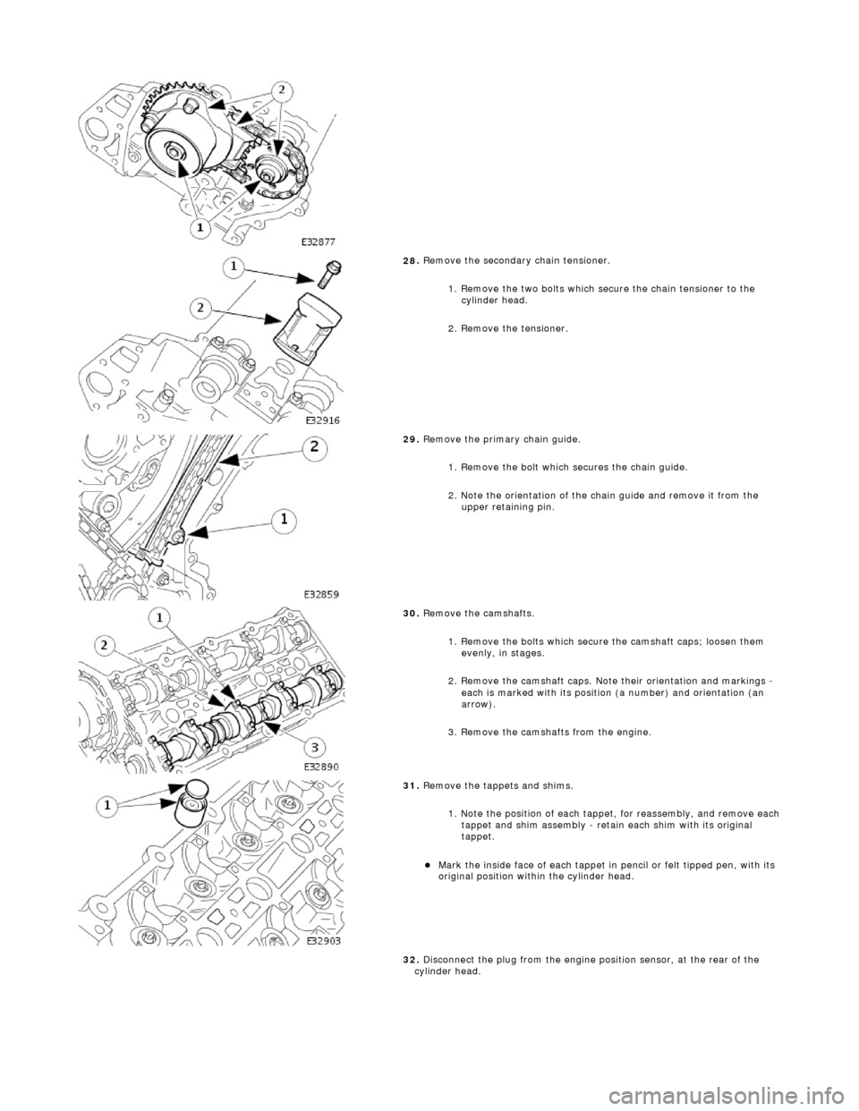
28
.
Remove the secondary chain tensioner.
1. Remove the two bolts which secure the chain tensioner to the cylinder head.
2. Remove the tensioner.
29
.
Remove the primary chain guide.
1. Remove the bolt which secures the chain guide.
2. Note the orientation of the chain guide and remove it from the upper retaining pin.
30
.
Remove the camshafts.
1. Remove the bolts which secure the camshaft caps; loosen them evenly, in stages.
2. Remove the camshaft caps. Note their orientation and markings -
each is marked with its position (a number) and orientation (an
arrow).
3. Remove the camshafts from the engine.
31
.
Remove the tappets and shims.
1. Note the position of each tappet, for reassembly, and remove each
tappet and shim assembly - retain each shim with its original
tappet.
пЃ¬Mark
the inside face of each tappet in pencil or felt tipped pen, with its
original position within the cylinder head.
32. Disconnect the plug from the engine position sensor, at the rear of the
cylinder head.
Page 622 of 2490

2. In
stall the camshaft caps to their respective locations (inlet 0 to 4
and exhaust 5 to 9 from the front) and in the correct orientation
(arrow to front of engine).
3. Install and tighten the cap securing bolts. Tighten evenly, in stages, to 10 Nm.
19. Install the camshaft locking tool 303 - 530, align the camshafts as
necessary.
20 . Install the chain guide
.
пЃ¬The
c
hain guide must be installed so that the slotted hole is towards
the top, and the rais ed shoulder to the cylinder block.
1. Install the chain guide to the block and locate it onto the upper retaining pin.
2. Install the retaining bolt and tighten it to 12 Nm.
21. P
ush the secondary chain tensioner piston into the body to provide
clearance for installing the chain.
1. Insert a thin rigid wire through the hole in the end of the tensioner
piston to displace the ball from the non-return valve seat.
2. With the wire in position, press the piston fully into the tensioner body.
пЃ¬Rem
ove the wire.
22 . Ins
tall the secondary chain tensioner to the engine.
1. Fully seat the tensioner to the cylinder head.
2. Install the two bolts which secure the tensioner and tighten to 12 Nm.
23 . N
OTE: Assemble the VVT unit, the exhaust camshaft sprocket and the
secondary chain, in preparation for installing to the engine.
Install the VVT unit to the engine.
1. Install the above assembly to the camshafts with the chain correctly positioned over the tensioner; VVT unit to the inlet and
the sprocket to the exhaust.
2. Install, but do not tighten, each bolt which secures the VVT unit and the exhaust sprocket to the camshafts.
24. Install the chain tensioning tool 303 - 532 to the exhaust camshaft
sprocket.
Page 623 of 2490

пЃ¬Re
position the sprocket (and the VVT unit) for the most advantageous
position for use of the tool.
пЃ¬R
emove the tool.
25
.
Install the primary timing chain.
пЃ¬R
eposition the VVT unit forwards on the cam journal (do not rotate it)
to allow the chain to cl ear the head casting. Disconnect the primary
chain from the Ty-strap.
1. Install the primary chain to position over the crankshaft sprocket and the VVT unit sprocket. There mu st be no slack on the drive
side of the primary chain and the VVT unit must not be rotated on
the camshaft.
26
.
Install the primary chain tensioner blade.
1. Position the tensioner blade to the cylinder block.
2. Install the retaining / pivot bolt and tighten it to 14 Nm.
27
.
Push the primary chain tensioner piston into the body to provide clearance
for installing.
1. Insert a thin rigid wire through the hole in the end of the tensioner
piston to displace the ball from the non-return valve seat.
2. With the wire in position, press the piston fully into the tensioner body.
пЃ¬Re
move the wire.
28
.
Assemble the tensioner.
1. Install the two mounting bolts to the tensioner.
2. Locate the tensioner back-plate to the two bolts.
29. Install the tensioner to the cylinder block.
1. Position and align the tensioner to the cylinder block and to the mating slot on the rear face of the tensioner blade.
2. Install and tighten the two bolts to 12 Nm.