JAGUAR X308 1998 2.G Workshop Manual
Manufacturer: JAGUAR, Model Year: 1998, Model line: X308, Model: JAGUAR X308 1998 2.GPages: 2490, PDF Size: 69.81 MB
Page 381 of 2490

6. CAUTI
ONS:
Only remove the bolts securi ng the caliper anchor bracket
to the hub carrier. Refer to caution above for more information.
Do not allow the caliper to hang on the hydraulic hose, as
this will damage the hose.
Remove caliper from hub carrier.
Re
move bolts.
Re
move and tie caliper aside.
7.
Ali
gn brake disc access hole
with parking brake adjuster.
R
emove plug from access hole.
Rotate
brake disc until ac
cess hole is aligned with
adjuster.
8. Slacken parking brake adju
ster to
allow for the removal of the
brake disc.
Rot
ate adjuster clockwise.
9. Remove brake disc from hub.
Page 382 of 2490

In
stallation
10
. R
emove brake dust from calipers, and from area of parking
brake shoes, see WARNING above.
11. Repeat above procedure to remo ve opposite side brake disc.
12. Thoroughly clean the area of both hubs where they mate
against the br ake discs.
1. Inst al
l brake disc to wheel studs.
Make su
re hu
b and brake disc
access holes are aligned.
2. Set the parking brake, refer to operation 70.35.37.
3. Check brake disc run-out. Refer to General Procedures section
206-04.
4. Inst al
l caliper to hub carrier.
Install and tigh
ten bolts to 6
0 Nm.
5. CAUTIONS:
Always install new brake pads, irrespective of the condition
of the original pads, when renewing brake discs.
Retracting the caliper piston may cause the fluid reservoir
to over-flow. Remove brake flui d spillage immediately from paint
work with clean water.
Page 383 of 2490

Note the condition of pins
and replace if necessary.
Install brake pads. Refer to 70 .40.09 for anti-squeal grease
application.
Sl
owly retract caliper pistons.
1. Install pads.
2. Position anti-rattle spring.
3. Install pins - make sure pin collets are fully engaged
into caliper.
6. Repeat
above procedure to inst
all opposite side brake disc.
7. Fit wheels. Refer to section 204-04.
8. Remove stands and lower vehicl e. Refer to section 100-02.
9. CAUTI
ON: Remove brake flui
d spillage immediately from
paint work, with clean water.
Check brake fluid level.
Check brak
e fluid level is
at the maximum mark.
Re
move cloth.
Fi
t cap.
10
.
Remove paint work protection covers, and close engine
compartment.
11. Start the engine and repeatedly press the brake pedal until
brake pressure is evident.
Page 384 of 2490

Rear Di
sc Brake - Brake PadsVe
hicles With: Standard Brakes
Remo
val and Installation
Remov
a
l
W
A
RNING: BRAKE DUST, IF INHALED CAN DAMAGE YOUR
HEALTH. ALWAYS REMOVE BRAKE DUST USING A VACUUM
BRUSH. DO NOT USE A COMPRESSED-AIR LINE TO DISPERSE BRAKE DUST INTO THE ATMOSPHERE.
CAUTION: Replacement of nuts and bolts: Various thread-locking devices are used on nuts and bolts throughout the
vehicle. These devices restrict the number of times a nut or bolt can be used. See section 100-00 for information.
1. Op
en engine compartment and fit
paint work protection covers
to fenders.
2. Raise rear of vehicl e and support on stan ds. See Section 100-
02.
3. Remove both rear wheels. See Section 204-04.
4. CAUTIO
N: Remove brake flui
d spillage immediately from
paint work, with clean water.
Loosen brake fluid reservoir-cap.
Position a cloth around the reser
voir to collect any fluid
spillage.
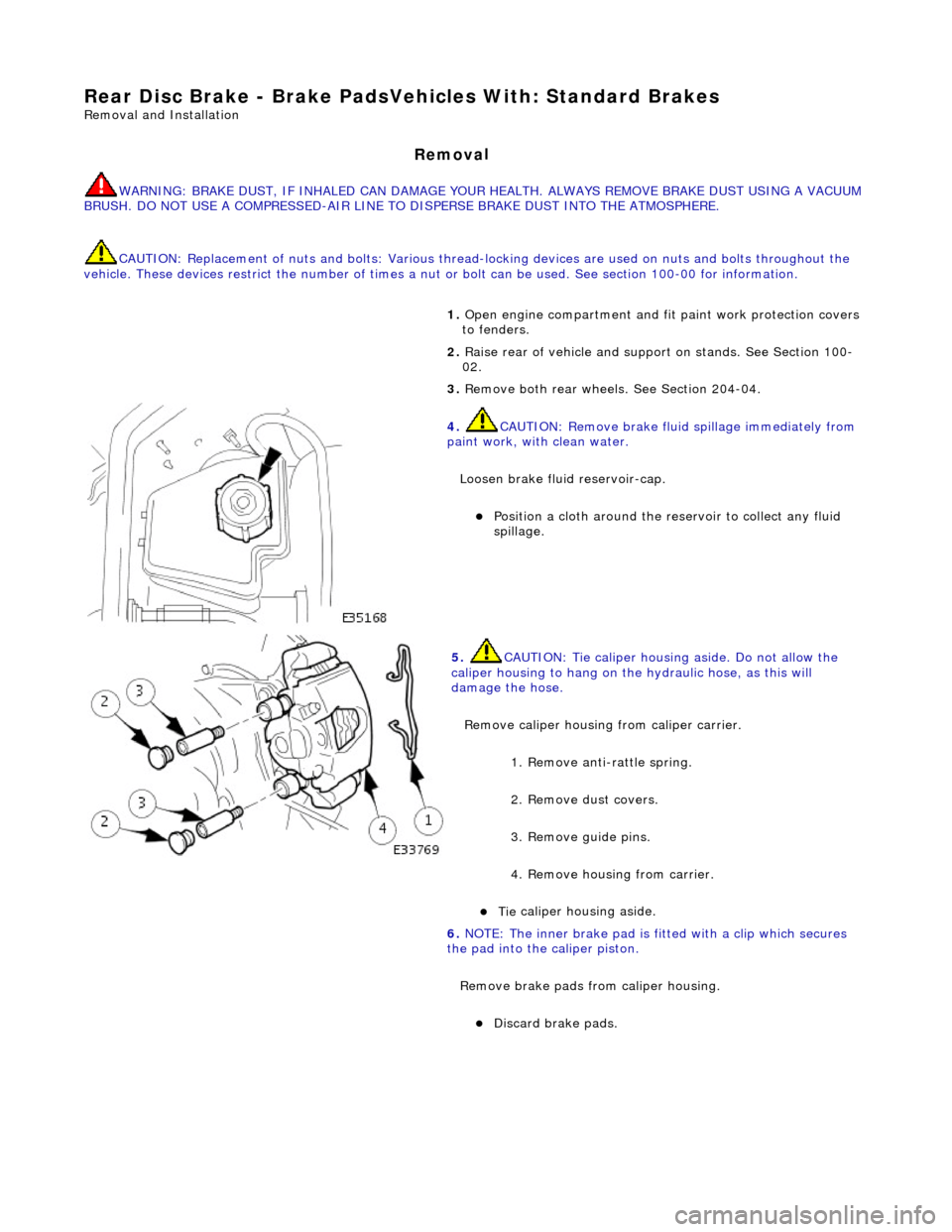
5. CAUT
ION: Tie caliper housing aside. Do not allow the
caliper housing to hang on the hydraulic hose, as this will
damage the hose.
Remove caliper housing from caliper carrier.
1. Remove anti-rattle spring.
2. Remove dust covers.
3. Remove guide pins.
4. Remove housing from carrier.
Tie
caliper housing aside.
6.
NO TE
: The inner brake pad is fitt
ed with a clip which secures
the pad into the caliper piston.
Remove brake pads from caliper housing.
Discard b
rake pads.
Page 385 of 2490

I
nstallation
7.
Cl
ean all mating surfaces and re
move brake dust. See Warning
above.
8. Repeat above procedure to remo ve opposite side brake pads.
1. CAUTI
ON: Retracting the caliper piston may cause the
fluid reservoir to over-flow. Remove brake fluid spillage
immediately from paint work, with clean water.
Slowly retract piston into caliper housing.
2. NOTE
: Clean caliper piston to pad mating surface.
Install brake pads to caliper housing.
Remove paper backing from pads to reveal
adhesive shim.
Install brake pads, in sert clip located on back of inner pad
into caliper piston.
3. Inst
all caliper housing to caliper carrier.
1. Align housing to carrier.
2. Install and tighten gu ide pins to 25-30 Nm.
3. Install dust covers.
4. Install anti-rattle spring.
4. Repeat above procedure to install opposite side brake pads.
5. Fit wheels. Refer to Section 204-04.
Page 386 of 2490

6.
Remove stan ds and lower veh
icl
e. Refer to Section 100-02.
7. CAUTI
O
N: Remove brake flui
d spillage immediately from
paint work, with clean water.
Check brake fluid level.
Check brak e flu
id level is
at the maximum mark.
Remo
ve cloth.
Fi
t ca
p.
8.
Re
move paint work protection
covers, and close engine
compartment.
9. Start the engine and repeatedly press the brake pedal until
brake pressure is evident.
Page 387 of 2490

Rear Dis
c Brake - Brake PadsVehicl
es With: High Performance Brakes
Re
moval and Installation
Remov
al
1.
W
ARNING: BRAKE DUST, IF INHALED CAN DAMAGE
YOUR HEALTH. ALWAYS REMOVE BRAKE DUST USING A VACUUM
BRUSH. DO NOT USE A COMPRE SSED-AIR LINE TO DISPERSE
BRAKE DUST INTO THE ATMOSPHERE. Failure to follow this
instruction may result in personal injury.
• CAUTIONS:
Brake pads must always be replaced in axle sets.
Replacement of nuts and bolts: Various thread-locking
devices are used on nuts and bolts throughout the vehicle. These
devices restrict the number of ti mes a nut or bolt can be used.
For additional information, refer to: General Service Information
(10
0-00 General Information,
Description and Operation).
The High performance brake caliper is aligned to the brake
disc when it is first installed to the vehicle, therefore, care must
be taken not to disturb this alignment. When removing the
caliper; remove the bolts that se cure the anchor bracket to the
vertical link only. DO NOT loosen any other caliper bolts.
Open engine compartment and fit paint work protection covers
to fenders.
2. R
aise rear of vehicle an
d support on stands.
For additional information, refer to: Using the Workshop Jack
(10
0-02 Jacking and Lifting, General Procedures).
3. Remove rear wheels.
For additional information, refer to: Wheel and Tire
(20
4-04
Wheels and Tires, Remo val and Installation).
4. CAUTI
ON: Remove brake flui
d spillage immediately from
paint work, with clean water.
Loosen brake fluid reservoir-cap.
Position a cloth around the
reservoir to collect any fluid
spillage.
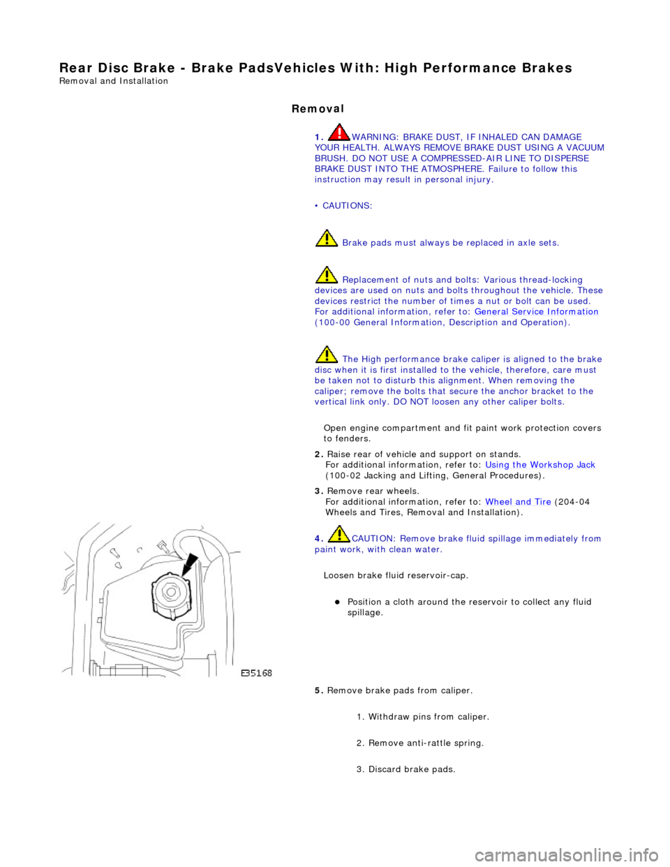
5. Remove brake
pads from caliper.
1. Withdraw pins from caliper.
2. Remove anti-rattle spring.
3. Discard brake pads.
Page 388 of 2490

In
stallation
6.
Clean all mating surfaces and remove brake du
st, see
WARNING above.
7. Repeat above procedure to remo ve opposite side brake pads.
1. CAUTIO
N: Make sure grease does not contact brake-pad
friction surface or brake disc.
To prevent brake squeal apply grease to the shoulders of the
brake-pad backplate.
For additional information, refer to: Specifications
(206-0
4 Rear
Disc Brake, Specifications).
Apply a un iform
layer of grea
se to backplate shoulders,
making sure the whole sh oulder is covered.
2. CAUTIO
N: Make sure the brake pads are fitted with the
direction arrow following the direction of wheel rotation.
Make sure the brake pads are fi tted with the direction arrow
following the direction of wheel rotation.
3. CAUTI O
NS:
Retracting the caliper piston may cause the fluid reservoir
to over-flow. Remove brake flui d spillage immediately from paint
work with clean water.
Make sure the brake pads are installed to the correct
orientation.
Make sure the brake pads ar e fitted with the direction
arrow following the direction of wheel rotation.
Note the condition of pins and replace if necessary.
• NOTE: Slowly retract caliper pistons.
Page 389 of 2490

Install brake pads.
1
. Install pads.
2. Position anti-rattle spring.
3. Install pins - make sure pin collets are fully engaged
into caliper.
4. Repeat above procedure to install opposite side brake pads.
5. Fit wheels.
For additional information, refer to: Wheel and Tire
(20
4-04
Wheels and Tires, Remo val and Installation).
6. Remove stands an d lower vehicle.
For additional information, refer to: Using the Workshop Jack
(10
0-02 Jacking and Lifting, General Procedures).
7. CAUTI
ON: Remove brake flui
d spillage immediately from
paint work, with clean water.
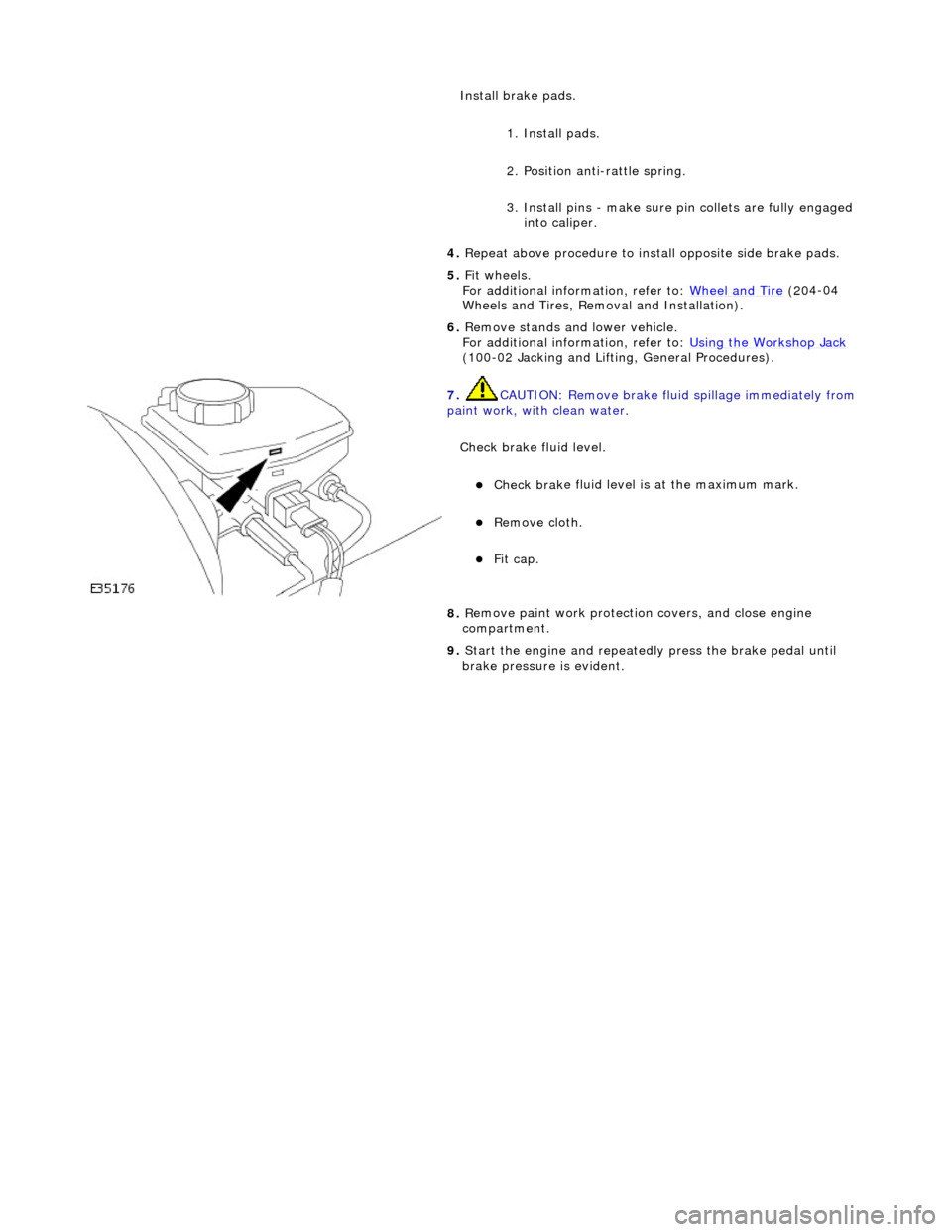
Check brake fluid level.
Check brak
e fluid level is
at the maximum mark.
Re
move cloth.
Fi
t cap.
8.
R
emove paint work protection
covers, and close engine
compartment.
9. Start the engine and repeatedly press the brake pedal until
brake pressure is evident.
Page 390 of 2490

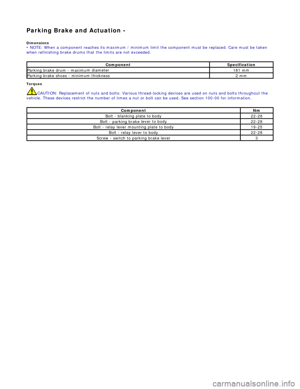
Parking Brake and Actuation -
Dim
ensions
• NO
TE: When a component reaches its maximum / minimum limit the component must be replaced. Care must be taken
when refinishing brake drums that the limits are not exceeded.
Torq ues
CAUTI
O
N: Replacement of
nuts and bolts: Various thread-locking devices are used on nuts and bolts throughout the
vehicle. These devices restrict the number of times a nut or bolt can be used. See section 100-00 for information.
Com p
onent
S
p
ecification
Parkin
g brake drum - maximu
m diameter
1
81 m
m
Parkin
g brake sh
oes - minimum thickness
2 m
m
Com p
onent
Nm
Bolt - blan
k
ing plate to body
22
-28
Bolt - park ing brake
lever to body
22
-28
Bolt - r
elay lever mounting plate to body
19
-25
Bo lt
- relay lever to body
22
-28
Screw - switch to parking brake lever3