JAGUAR X308 1998 2.G Workshop Manual
Manufacturer: JAGUAR, Model Year: 1998, Model line: X308, Model: JAGUAR X308 1998 2.GPages: 2490, PDF Size: 69.81 MB
Page 361 of 2490
Front Dis
c Brake - Brake PadsVehicl
es With: High Performance Brakes
Re
moval and Installation
Remov
al
1.
W
ARNING: BRAKE DUST, IF INHALED CAN DAMAGE
YOUR HEALTH. ALWAYS REMOVE BRAKE DUST USING A VACUUM
BRUSH. DO NOT USE A COMPRE SSED-AIR LINE TO DISPERSE
BRAKE DUST INTO THE ATMOSPHERE. Failure to follow this
instruction may result in personal injury.
• CAUTIONS:
Brake pads must always be replaced in axle sets.
Replacement of nuts and bolts: Various thread-locking
devices are used on nuts and bolts throughout the vehicle. These
devices restrict the number of ti mes a nut or bolt can be used.
For additional information, refer to: General Service Information
(10
0-00 General Information,
Description and Operation).
The High Performance brake ca liper is aligned to the brake
disc when it is first installed to the vehicle, therefore, care must
be taken not to disturb this alignment. When removing the
caliper; remove the bolts that se cure the anchor bracket to the
vertical link only. DO NOT loosen any other caliper bolts.
Open engine compartment and fit paint work protection covers
to fenders.
2. R
aise front of vehicle an
d support on stands.
For additional information, refer to: Using the Workshop Jack
(10
0-02 Jacking and Lifting, General Procedures).
3. Remove front wheels. Refer to operation.
For additional information, refer to: Wheel and Tire
(20
4-04
Wheels and Tires, Remo val and Installation).
4. CAUTI
ON: Remove brake flui
d spillage immediately from
paint work, with clean water.
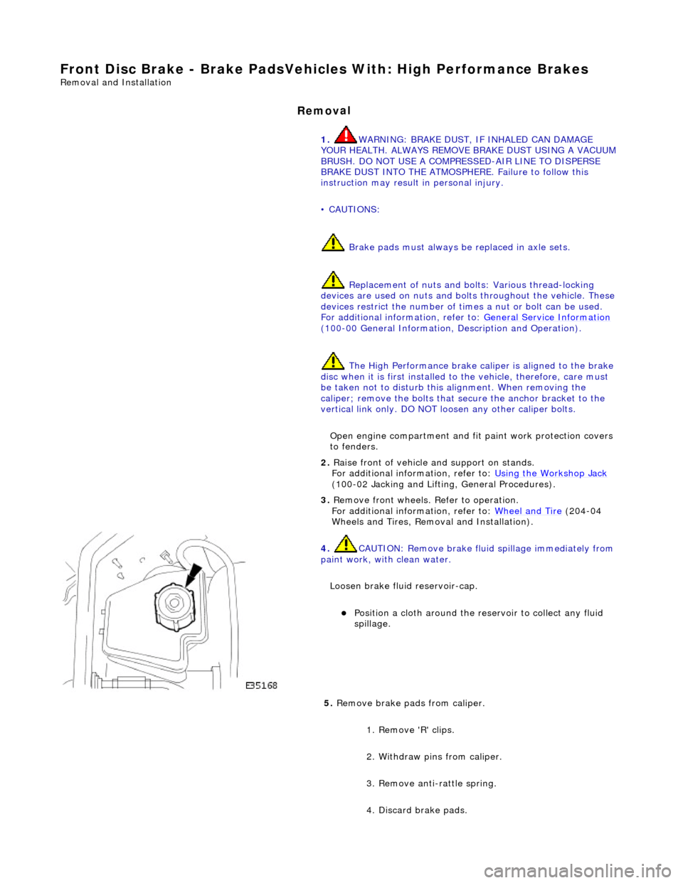
Loosen brake fluid reservoir-cap.
Position a cloth around the
reservoir to collect any fluid
spillage.
5. Remove brake
pads from caliper.
1. Remove 'R' clips.
2. Withdraw pins from caliper.
3. Remove anti-rattle spring.
4. Discard brake pads.
Page 362 of 2490

In
stallation
6.
Clean all mating su rfaces and remove brake du
st, see
WARNING above.
7. Repeat above procedure to remo ve opposite side brake pads.
1. CAUTIO
N: Make sure grease does not contact brake-pad
friction surface or brake disc.
To prevent brake squeal apply grease to the shoulders of the
brake-pad backplate.
For additional information, refer to: Specifications
(206-0
4 Rear
Disc Brake, Specifications).
Apply a un iform
layer of grea
se to backplate shoulders,
making sure the whole sh oulder is covered.
2. CAUTIO
N: Make sure the brake pads are fitted with the
direction arrow following the direction of wheel rotation.
Make sure the brake pads are fi tted with the direction arrow
following the direction of wheel rotation.
3. CAUTI O
NS:
Retracting the caliper piston may cause the fluid reservoir
to over-flow. Remove brake flui d spillage immediately from paint
work, with clean water.
Make sure the brake pads are installed to the correct
orientation.
Make sure the brake pads ar e fitted with the direction
arrow following the direction of wheel rotation.
Note condition of pins an d 'R' clips and replace if
necessary.
Page 363 of 2490
Install brake pads
i
nto caliper.
Slo
wly retract caliper pi
stons into caliper.
1. Install pads.
2. Position anti-rattle spring.
3. Install pins.
4. Install 'R' clips.
4. Repeat above procedure to install opposite side brake pads.
5. Fit wheels.
For additional information, refer to: Wheel and Tire
(20
4-04
Wheels and Tires, Remo val and Installation).
6. Remove stands and lower vehicle.
For additional information, refer to: Using the Workshop Jack
(10
0-02 Jacking and Lifting, General Procedures).
7. CAUTI
ON: Remove brake flui
d spillage immediately from
paint work, with clean water.
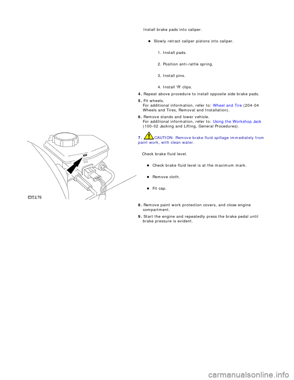
Check brake fluid level.
Check brak
e fluid level is
at the maximum mark.
Re
move cloth.
Fi
t cap.
8.
R
emove paint work protection
covers, and close engine
compartment.
9. Start the engine and repeatedly press the brake pedal until
brake pressure is evident.
Page 364 of 2490
Rear Disc Brake -
Lubric
ants, Fluids, Sealants and Adhesives
CAUTI
O
N: Do not use brake fluid ITT Supe
r Dot 4 on 2006my vehicles onwards. Fa ilure to follow this instruction may
result in damage to the vehicle.
• NOTE: Brake fluid ITT Super Dot 4 has now been superseded by Shell ESL Super Dot 4 which is the Jaguar recommended
brake fluid. Shell ESL Super Dot 4 can be used on all model years.
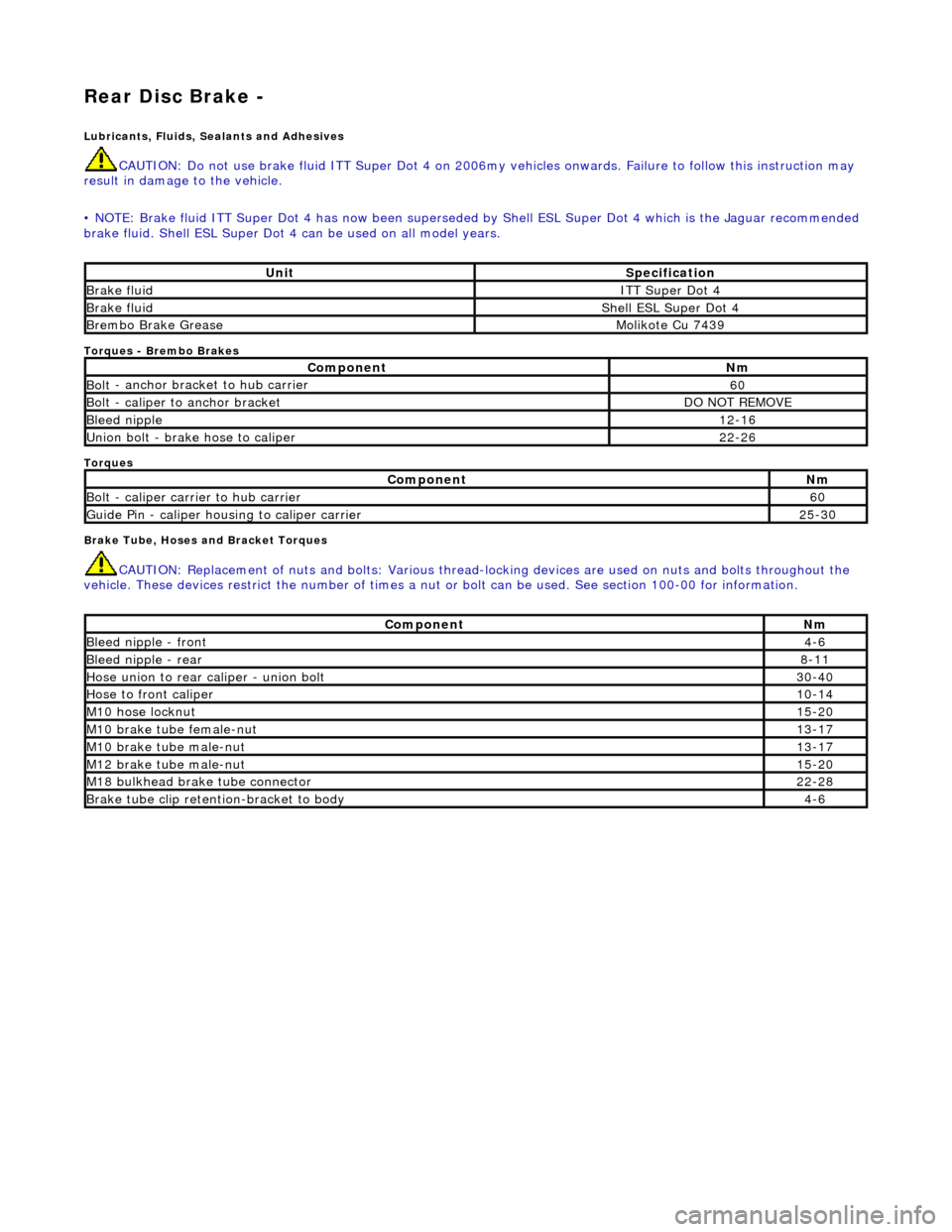
Torques
- Brembo Brakes
Torques
Brake Tube, Hoses and Bracket Torques
CAUTIO
N: Replacement of
nuts and bolts: Various thread-locking devices are used on nuts and bolts throughout the
vehicle. These devices restrict the number of times a nut or bolt can be used. See section 100-00 for information.
UnitS p
ecification
Brake flu
i
d
ITT Supe
r Dot 4
Brake flui
d
Shell E
SL Supe
r Dot 4
Brem
bo Brake G
rease
Mol
i
kote Cu 7439
Com
p
onent
Nm
Bol
t
- anchor bracket to hub carrier
60
B
o
lt - caliper to anchor bracket
DO
N
OT REMOVE
Bleed n
i
pple
12
-16
Un
ion bolt - brake hose to caliper
22
-26
Com p
onent
Nm
Bol
t
- caliper carrier to hub carrier
60
Guide
Pi
n - caliper housing to caliper carrier
25
-30
Comp
onent
Nm
Bleed ni
pple - front
4-6
Bleed ni
pple - rear
8-11
Hose union to rear cal
i
per - union bolt
30
-40
Hose to fr ont cal
iper
10
-14
M1 0 h
ose locknut
15
-20
M10 brake
tube female-nut
13
-17
M10 brake
tube male-nut
13
-17
M12 brake
tube male-nut
15
-20
M18 bu
lkhead brake tube connector
22
-28
Brake tube clip retention -
bracket to body
4-
6
Page 365 of 2490
Rear
Disc Brake - Rear Disc Brake
Description an
d Operation
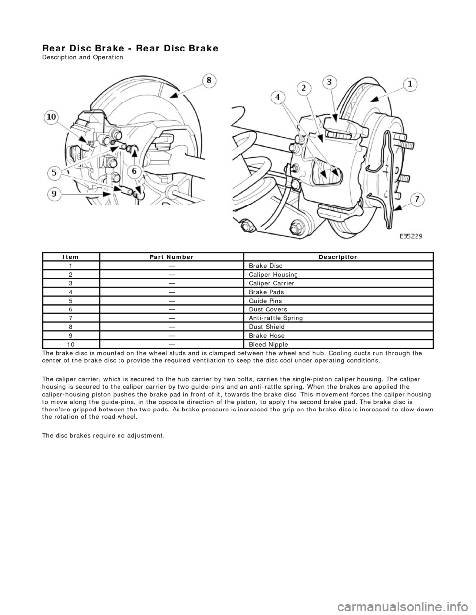
The brake disc is mounted on the wheel studs and is clamped between the wheel and hub. Cooling ducts run through the
center of the brake disc to provide the required ventilation to keep the disc cool under operating conditions.
The caliper carrier, which is se cured to the hub carrier by two bolts, carries the single-piston caliper housing. The caliper
housing is secured to the caliper carrier by two guide-pins and an anti-rattle spring. When the brakes are applied the
caliper-housing piston pushes th e brake pad in front of it, towards the brake di sc. This movement forces the caliper housing
to move along the guide-pins, in the oppo site direction of the piston, to apply the second brake pad. The brake disc is
therefore gripped between the two pads. As brake pressure is increased the grip on the brake disc is increased to slow-down
the rotation of the road wheel.
The disc brakes requ ire no adjustment.
It
em
Par
t Number
De
scription
1—B
rake Disc
2—Caliper Housin
g
3—Caliper Carrier
4—Brake Pad
s
5—Guide P
ins
6—Du
st Covers
7—An
ti-rattle Spring
8—Du
st Shield
9—Brake Hos
e
10—Bleed Nipp
le
Page 366 of 2490
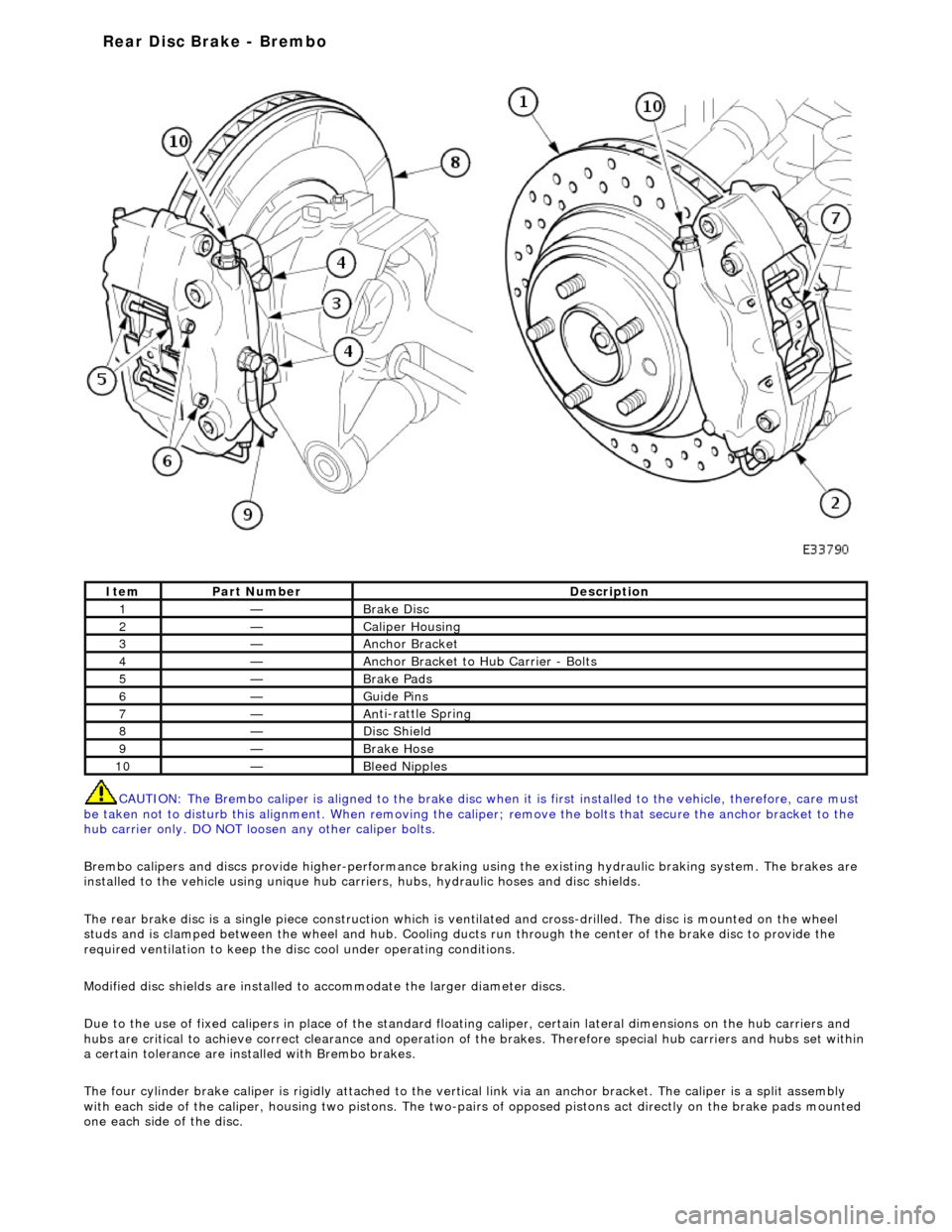
CAUTI O
N: The Brembo caliper is aligned to
the brake disc when it is first installed to the vehicle, therefore, care must
be taken not to disturb this alignment. When removing the ca liper; remove the bolts that secure the anchor bracket to the
hub carrier only. DO NOT loos en any other caliper bolts.
Brembo calipers and discs provide higher -performance braking using the existing hydraulic braking system. The brakes are
installed to the vehicle using unique hub carr iers, hubs, hydraulic hoses and disc shields.
The rear brake disc is a single piece co nstruction which is ventilated and cross-drilled. The disc is mounted on the wheel
studs and is clamped between the wheel and hub. Cooling ducts run through the ce nter of the brake disc to provide the
required ventilation to keep the disc cool under operating conditions.
Modified disc shields are installed to accommodate the larger diameter discs.
Due to the use of fixed calipers in place of the standard floating caliper, certain lateral dimensions on the hub carriers and
hubs are critical to achieve correct cleara nce and operation of the brakes. Therefore special hub carriers and hubs set within
a certain tolerance are inst alled with Brembo brakes.
The four cylinder brake caliper is rigidly attached to the vert ical link via an anchor bracket. The caliper is a split assembly
with each side of the caliper, housing two pistons. The two-pairs of opposed pistons act direct ly on the brake pads mounted
one each side of the disc.
It e
m
Par
t
Number
De
scr
iption
1—Brake D
i
sc
2—Caliper Housin
g
3—Anchor Bracke
t
4—Anchor Bracket to H
u
b Carrier - Bolts
5—Brake Pads
6—Guide Pi
ns
7—An
ti
-rattle Sprin
g
8—Di
sc
Shield
9—Brake Hos
e
10—Bleed Nipp
les
Rear Disc Brake - Brembo
Page 367 of 2490

Stai
nless steel hydraulic hoses connect the calipers to the existi
ng brake tubes. It is important that these hoses are aligned
correctly when installed to pr event them fouling on the steering and suspen sion components. Refer to operation 70.55.25
for information.
The Brembo disc brakes require no adjustment.
Page 368 of 2490
Rear Disc Brake - Brake CaliperVehicles W
ith: Standard Brakes
Re
mo
val and Installation
Remov
a
l
WA
RNING: BRAKE DUST, IF INHALED CAN DAMAGE YOUR
HEALTH. ALWAYS REMOVE BRAKE DUST USING A VACUUM
BRUSH. DO NOT USE A COMPRESSED-AIR LINE TO DISPERSE BRAKE DUST INTO THE ATMOSPHERE.
• CAUTIONS:
Replacement of nuts and bolts: Various thread-locking de vices are used on nuts and bolts throughout the vehicle.
These devices restrict the number of times a nut or bolt can be used. See section 100-00 for information.
Remove brake fluid spilla ge immediately from paint work, with clean water.
The brake pad adhesive backing must not be reused, therefore always install new brake pads, irrespective of the
condition of the original pads when replacing a brake caliper. Always replace brake pads as an axle set.
Sp
ecial Tool(s)
Brake Pedal
H
old Tool
JDS 9013
1. Op
en luggage compartment lid and fit suitable paintwork
protection equipment.
2. Raise vehicle on a four-post lift.
3. Raise rear of vehicl e and support on stan ds. See Section 100-
02.
4. Remove rear wheel. See Section 204-04.
5. NOTE
: Th
e following three pictorial procedures must be
carried-out to minimize brake fl uid loss when disconnecting the
brake hose.
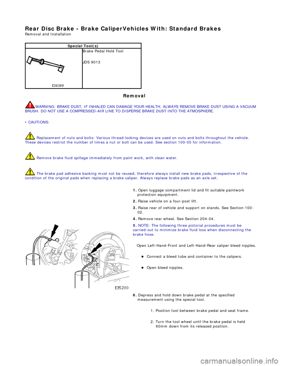
Open Left-Hand-Front and Left-H and-Rear caliper bleed nipples.
Connect a
bleed tube and co
ntainer to the calipers.
Op
en bleed nipples.
6. Depress and hold down brak e pedal at the specified
measurement using the special tool.
1. Position tool between brake pedal and seat frame.
2. Turn the tool wheel unti l the brake pedal is held
60mm down from its released position.
Page 369 of 2490

7. Close bleed nipples on
both calipers.
Remove bleed tub
es and containers.
Tigh
ten front bleed nipple to 4-6 Nm.
Tigh
ten rear bleed nipple to 8-11 Nm.
8. Di
sconnect brake hose from
rear caliper housing.
Install plugs to caliper
and brake hose.
9. R
emove caliper housing from caliper carrier.
1. Remove anti-rattle spring.
2. Remove dust covers.
3. Remove guide pins.
4. Remove housing from carrier.
10. NOTE: The inner brake pad is fitt ed with a clip which secures
the pad into the caliper piston.
Remove and discard brake pa ds. (See Caution above).
Page 370 of 2490
In
stallation
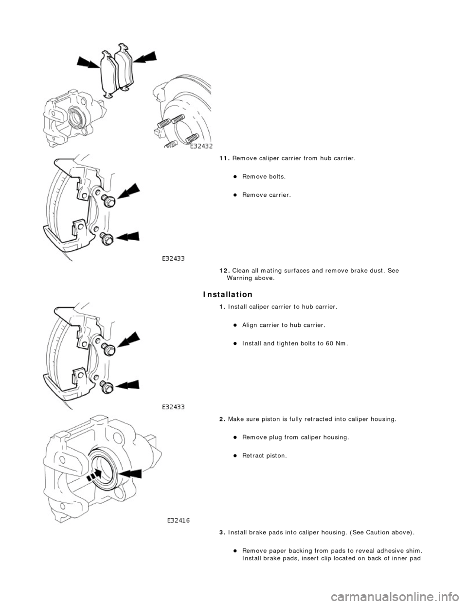
11
. R
emove caliper carrier from hub carrier.
Re
mo
ve bolts.
R
e
move carrier.
12. Clean all mating surfaces and remove brake dust. See
Warning above.
1. Inst al
l caliper carri
er to hub carrier.
Align c
arrier to hub carrier.
Install and tighten bolts to 6
0 Nm.
2. Make sure piston i
s
fully re
tracted into caliper housing.
R
e
move plug from caliper housing.
Re
tr
act piston.
3. Install brake pads in to caliper housing. (See Caution above).
Remove paper backing from pads to reveal adhesive shi
m.
Install brake pads, in sert clip located on back of inner pad