Seat JAGUAR X308 1998 2.G Owner's Guide
[x] Cancel search | Manufacturer: JAGUAR, Model Year: 1998, Model line: X308, Model: JAGUAR X308 1998 2.GPages: 2490, PDF Size: 69.81 MB
Page 182 of 2490

Withdraw th
e hub carrier and support on a block of wood.
9. CAUTIO
N: Note the position of
the shims during removal.
They must be returned to th eir original position during
installation.
Noting their positions, remove the shim from each end of the
pivot pin sleeve.
10 . WAR
NINGS:
ENSURE THE SPECIAL TOOLS ARE POSITIONED
DIAMETRICALLY OPPOSITE ON THE SPRING AND THE ARMS ARE
CORRECTLY SEATED .
WHEN COMPRESSING THE SPRING, TIGHTEN THE
SPECIAL-TOOL ADJUSTMENT BOLTS EVENLY.
Compress the spring.
Install and alig n th
e special
tools 204-179 diametrically
opposite on the spring.
Eve n
ly tighten the special tool tensioning bolts to
compress the spring.
11 . R
emove the shock absorber to
wishbone mounting nut and
bolt.
12. Remove the nuts securing th e shock absorber and spring
upper mounting to the body.
Page 184 of 2490

18. Lower and remove the
jack.
19. Remove the shock absorber an d spring assembly from the
vehicle and place the assembly on a work bench.
20. Clean the upper mounting spring location.
21 . Remove the
pigtail seat and cl
ean the wishbone lower spring
location.
22 . W
ith assistance, manually compress the shock absorber and
withdraw the bolt from the spring coils.
23 . R
emove the shock absorber from the upper mounting.
Posi
ti
on a wrench on the shock absorber shaft flats to
prevent rotation (wrench in socket on vehicles with
adaptive damping).
R e
move the shock absorber
upper retaining nut.
Remove the u
pper washer and isolator.
24. Remove the special tools 204-179-1 and remove the upper
mounting from the spring.
Page 185 of 2490
I
nstallation
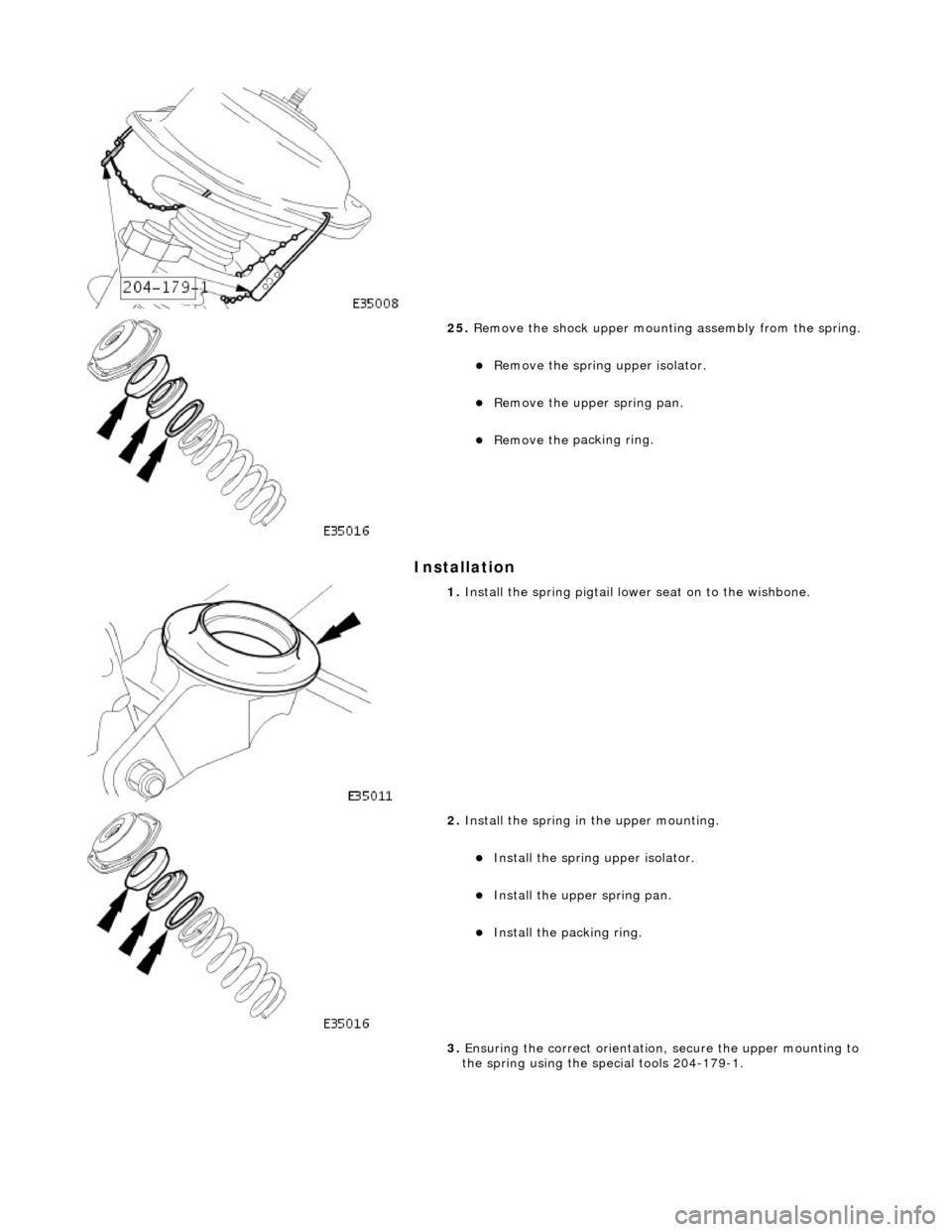
25
.
Remove the shock upper mounting assembly from the spring.
R
emove the spring
upper isolator.
Remove the
upper spring pan.
Remove the
packing ring.
1. Install th
e spring pigtail lower seat on to the wishbone.
2. Install
the spring in
the upper mounting.
Install
the spring upper isolator.
Install
the upper spring pan.
Inst
all the packing ring.
3. Ensuring the correct orientation, secure the upper mounting to
the spring using the special tools 204-179-1.
Page 188 of 2490
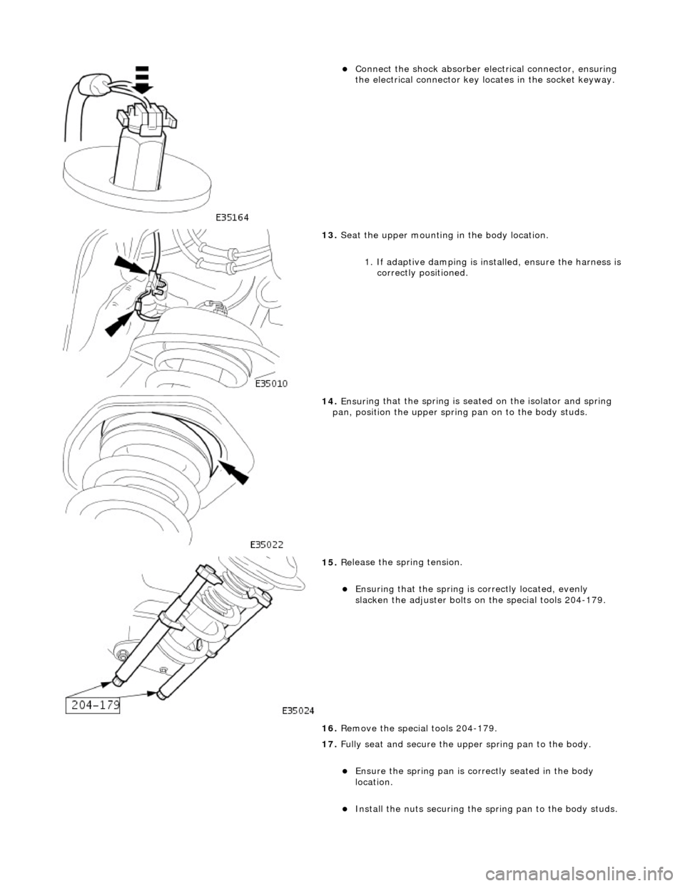
Connect
the shock absorber elec
trical connector, ensuring
the electrical connector key locates in the socket keyway.
13. Seat
the upper mounting in the body location.
1. If adaptive damping is installed, ensure the harness is
correctly positioned.
14 . Ensuri
ng that the spri
ng is seated on the isolator and spring
pan, position the u pper spring pan on to the body studs.
15 . Re
lease the spring tension.
Ensuri
ng that the spri
ng is
correctly located, evenly
slacken the adjuster bolts on the special tools 204-179.
16. Remove the special tools 204-179.
17. Fully seat and secure the u pper spring pan to the body.
Ensure the spring pan i
s correctly seated in the body
location.
Inst al
l the nuts securing the sp
ring pan to the body studs.
Page 189 of 2490
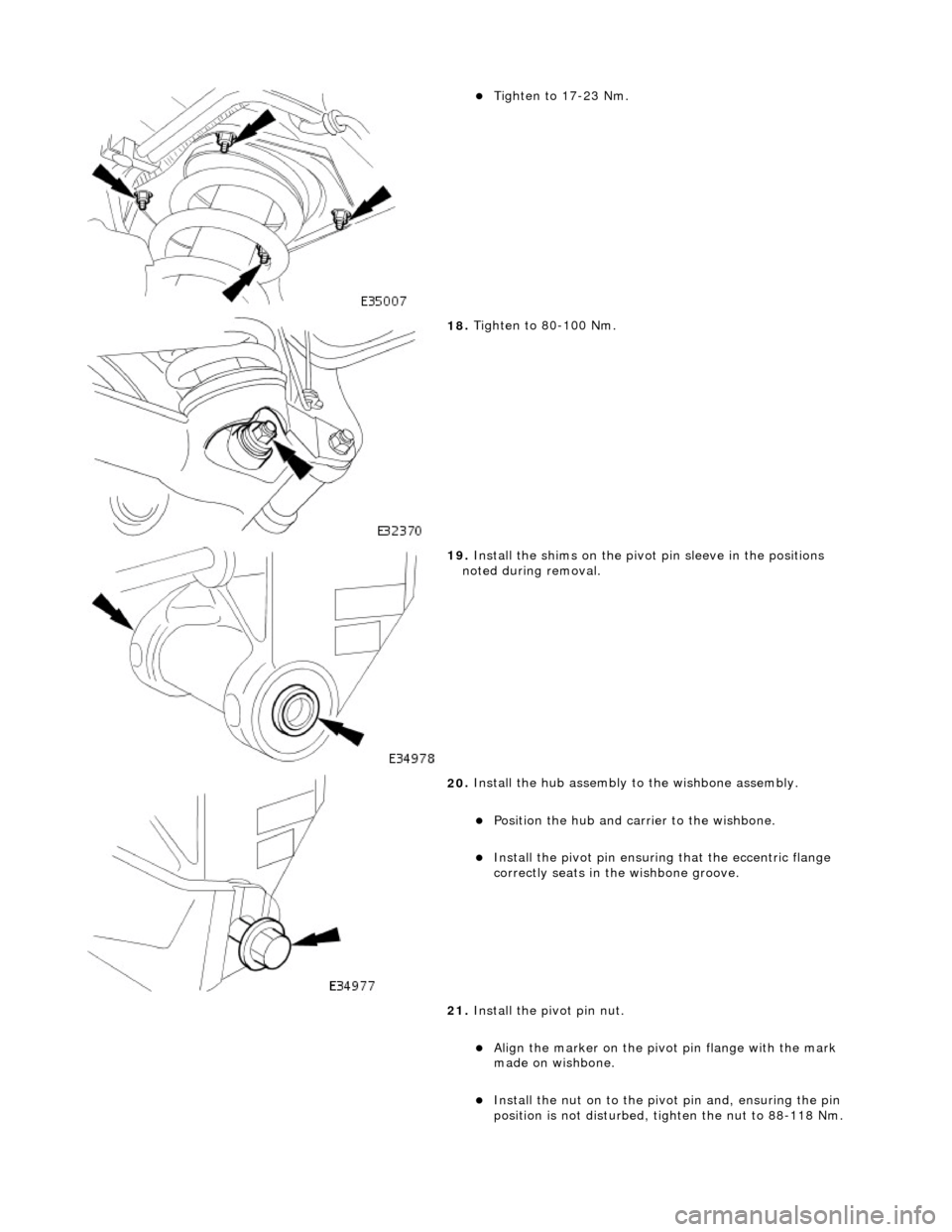
Tigh
ten to 17-23 Nm.
18
.
Tighten to 80-100 Nm.
19
.
Install the shims on the pivot pin sleeve in the positions
noted during removal.
20
.
Install the hub assembly to the wishbone assembly.
Position the hub and carri
er to the wishbone.
Inst
all the pivot pin ensuring that the ecce
ntric flange
correctly seats in the wishbone groove.
21. Install the pivot pin nut.
Ali
gn the marker on the pivo
t pin flange with the mark
made on wishbone.
Inst
all the nut on to the pivot pin and, ensuring the pin
position is not dist urbed, tighten the nut to 88-118 Nm.
Page 197 of 2490

With
draw the hub carrier and support on a block of wood.
9. CAUTI
ON: Note the position of
the shims during removal.
They must be returned to th eir original position during
installation.
Noting their positions, remove the shim from each end of the
pivot pin sleeve.
10
.
WARNINGS:
ENSURE THE SPECIAL TOOLS ARE POSITIONED
DIAMETRICALLY OPPOSITE ON THE SPRING AND THE ARMS ARE
CORRECTLY SEATED .
WHEN COMPRESSING THE SPRING, TIGHTEN THE
SPECIAL-TOOL ADJUSTMENT BOLTS EVENLY.
Compress the spring.
Install and alig
n the special
tools 204-179 diametrically
opposite on the spring.
Eve
nly tighten the special tool tensioning bolts to
compress the spring.
11
.
Remove the shock absorber to wishbone mounting nut and
bolt.
12. Remove the nuts securing th e shock absorber and spring
upper mounting to the body.
Page 199 of 2490

18
.
Lower and remove the jack.
19. Remove the shock absorber an d spring assembly from the
vehicle and place the assembly on a work bench.
20. Clean the upper mounting spring location.
21
.
Remove the pigtail seat and cl ean the wishbone lower spring
location.
22
.
With assistance, manually compress the shock absorber and
withdraw the bolt from the spring coils.
23
.
Remove the shock absorber from the upper mounting.
Posi
tion a wrench on the shock absorber shaft flats to
prevent rotation (wrench in socket on vehicles with
adaptive damping).
R
emove the shock absorber
upper retaining nut.
Remove the
upper washer and isolator.
24. Remove the special tools 204-179-1 and remove the upper
mounting from the spring.
Page 201 of 2490
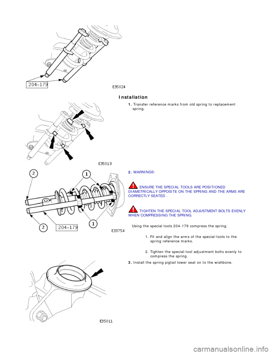
I
nstallation
1.
Transfer r
eference marks from
old spring to replacement
spring.
2. WAR
NINGS:
ENSURE THE SPECIAL TOOLS ARE POSITIONED
DIAMETRICALLY OPPOSITE ON THE SPRING AND THE ARMS ARE
CORRECTLY SEATED .
TIGHTEN THE SPECIAL TOOL ADJUSTMENT BOLTS EVENLY
WHEN COMPRESSING THE SPRING.
Using the special tools 204-179 compress the spring.
1. Fit and align the arms of the special-tools to the spring reference marks.
2. Tighten the special-tool adjustment bolts evenly to compress the spring.
3. Install th
e spring pigtail lower seat on to the wishbone.
Page 204 of 2490
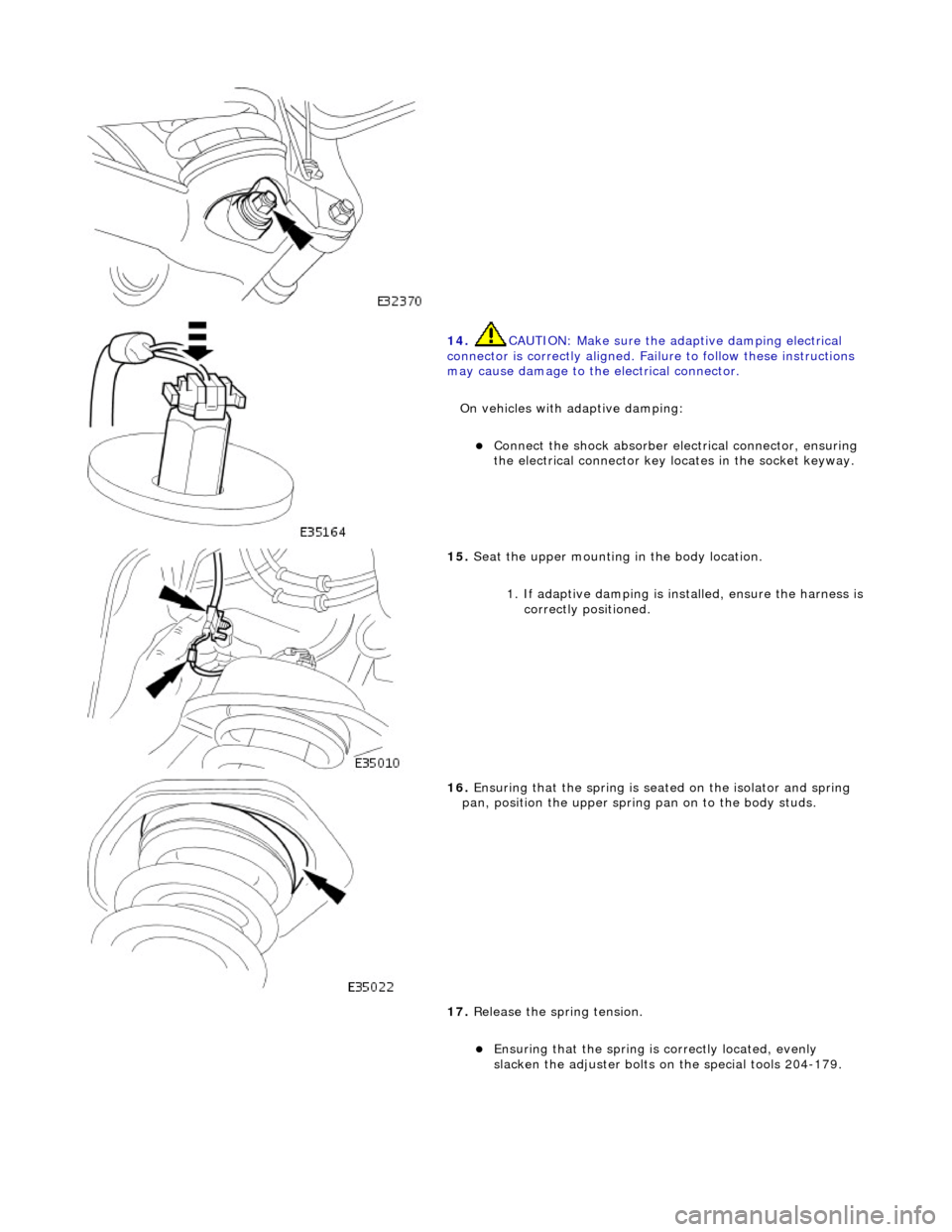
14. CAUTI
ON: Make sure the adaptive damping electrical
connector is correctly aligned. Failu re to follow these instructions
may cause damage to the electrical connector.
On vehicles with adaptive damping:
Conne ct
the shock absorber elec
trical connector, ensuring
the electrical connector key locates in the socket keyway.
15 . Seat
the upper mounting in the body location.
1. If adaptive damping is installed, ensure the harness is
correctly positioned.
16 . Ensuri
ng that the spri
ng is seated on the isolator and spring
pan, position the u pper spring pan on to the body studs.
17. Release the spring tension.
Ensuring that the spri
ng is
correctly located, evenly
slacken the adjuster bolts on the special tools 204-179.
Page 205 of 2490
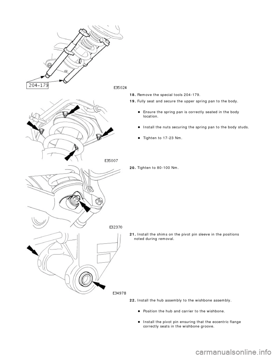
18
.
Remove the special tools 204-179.
19
.
Fully seat and secure the u pper spring pan to the body.
Ensure the spri
ng pan is correctly seated in the body
location.
Inst
all the nuts securing the sp
ring pan to the body studs.
Tigh
ten to 17-23 Nm.
20
.
Tighten to 80-100 Nm.
21
.
Install the shims on the pivot pin sleeve in the positions
noted during removal.
22. Install the hub assembly to the wishbone assembly.
Position the hub and carri
er to the wishbone.
Inst
all the pivot pin ensuring that the ecce
ntric flange
correctly seats in the wishbone groove.