JAGUAR X308 1998 2.G Workshop Manual
Manufacturer: JAGUAR, Model Year: 1998, Model line: X308, Model: JAGUAR X308 1998 2.GPages: 2490, PDF Size: 69.81 MB
Page 541 of 2490
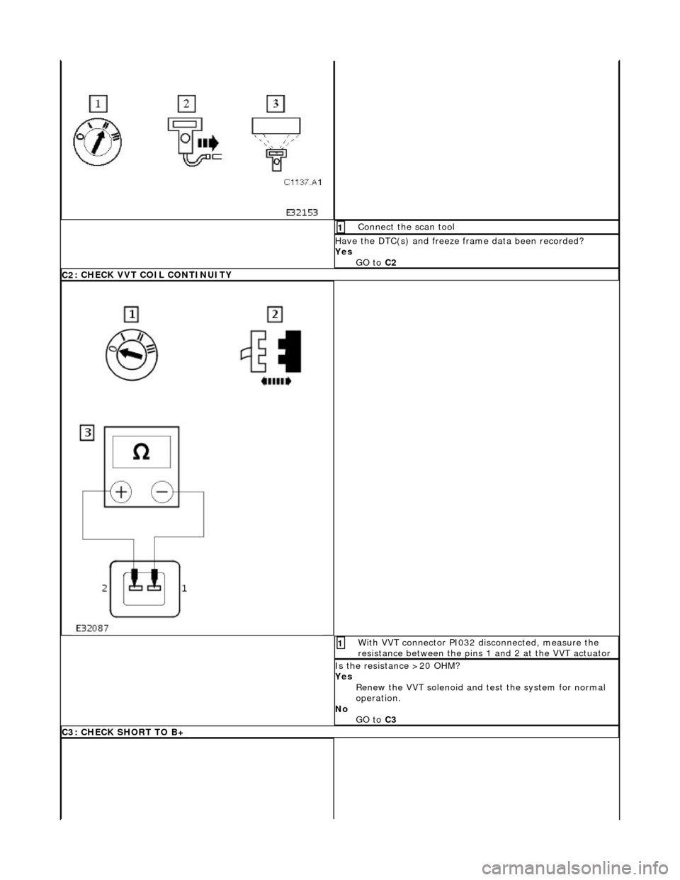
Conne
ct the scan tool
1
Have the DTC(s) and fr
eeze
frame data been recorded?
Yes GO to C2
C2
: CHECK VVT COIL CONTINUITY
Wi
th VVT connector PI032 disconnected, measure the
resistance between the pins 1 and 2 at the VVT actuator
1
I
s the resistance >20 OHM?
Yes Renew the VVT solenoid and te st the system for normal
operation.
No GO to C3
C3
: CHECK SHORT TO B+
Page 542 of 2490
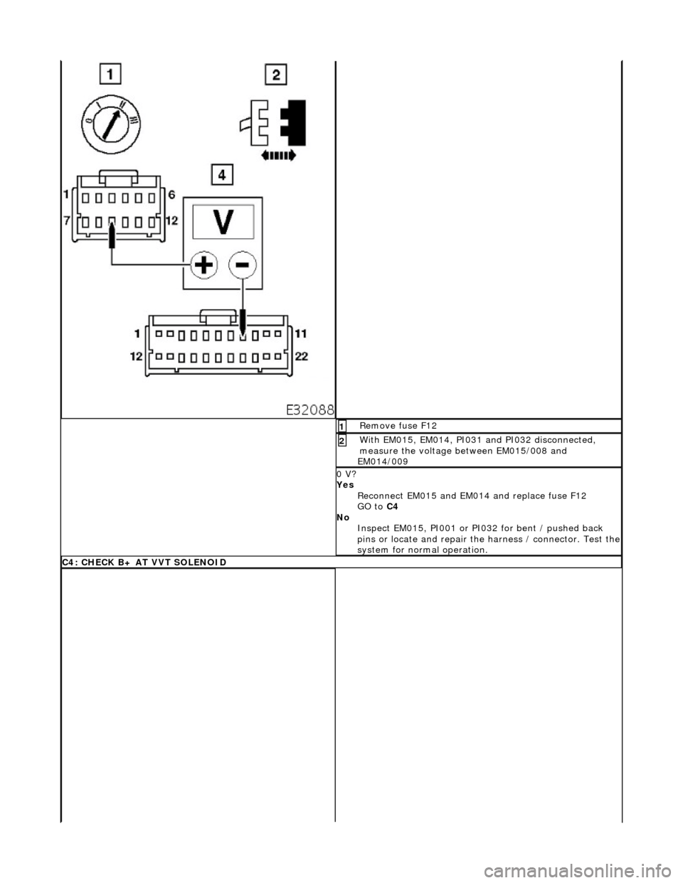
Re
move fuse F12
1
W
i
th EM015, EM014, PI031 and PI032 disconnected,
measure the voltage between EM015/008 and
EM014/009
2
0 V?
Yes
Reconnect EM015 and EM0 14 and replace fuse F12
GO to C4
No Inspect EM015, PI001 or PI032 for bent / pushed back
pins or locate and repair the harness / connector. Test the
system for normal operation.
C4 :
CHECK B+ AT VVT SOLENOID
Page 543 of 2490
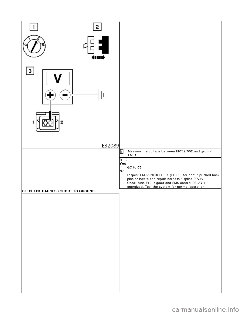
Me
asure the voltage between PI032/002 and ground
EM016L
1
B+ ?
Yes
GO to C5
No Inspect EM020/010 PI031 (PI032) for bent / pushed back
pins or locate and repair harness / splice PIS06.
Check fuse F12 is good and EMS control RELAY 1
energized. Test the system for normal operation.
C
5: CHECK HARNESS SHORT TO GROUND
Page 544 of 2490
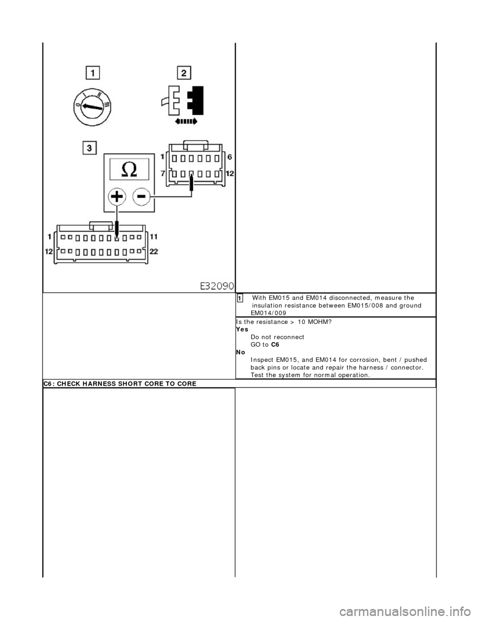
Wi
th EM015 and EM014 disconnected, measure the
insulation resistance between EM015/008 and ground
EM014/009
1
Is
the resistance > 10 MOHM?
Yes Do not reconnect
GO to C6
No Inspect EM015, and EM014 for corrosion, bent / pushed
back pins or locate and repa ir the harness / connector.
Test the system for normal operation.
C6:
CHECK HARNESS SHORT CORE TO CORE
Page 545 of 2490
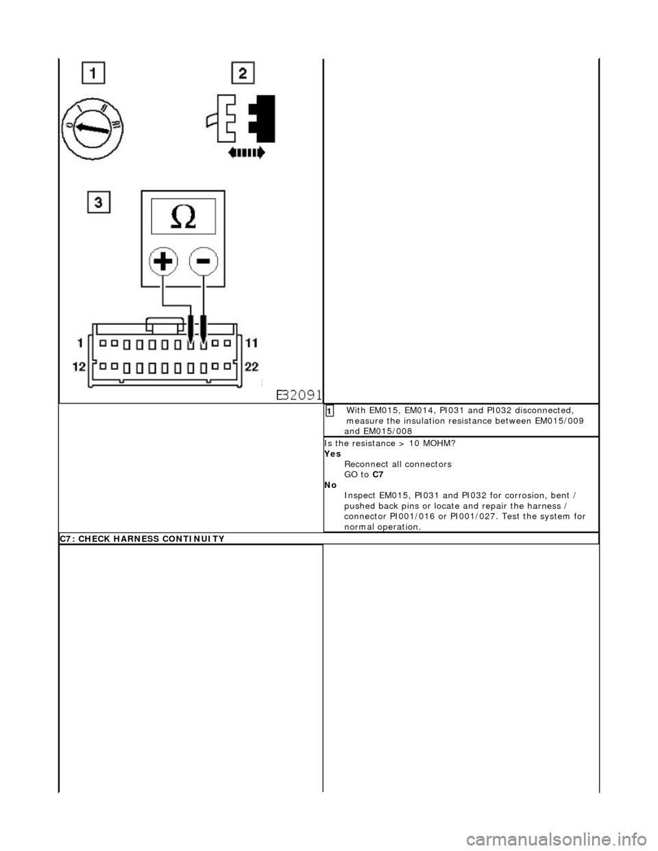
W
ith EM015, EM014, PI031 and PI032 disconnected,
measure the insulation resistance between EM015/009
and EM015/008
1
I
s the resistance > 10 MOHM?
Yes Reconnect all connectors
GO to C7
No Inspect EM015, PI031 and PI032 for corrosion, bent /
pushed back pins or locate and repair the harness /
connector PI001/016 or PI001 /027. Test the system for
normal operation.
C7
: CHECK HARNESS CONTINUITY
Page 546 of 2490
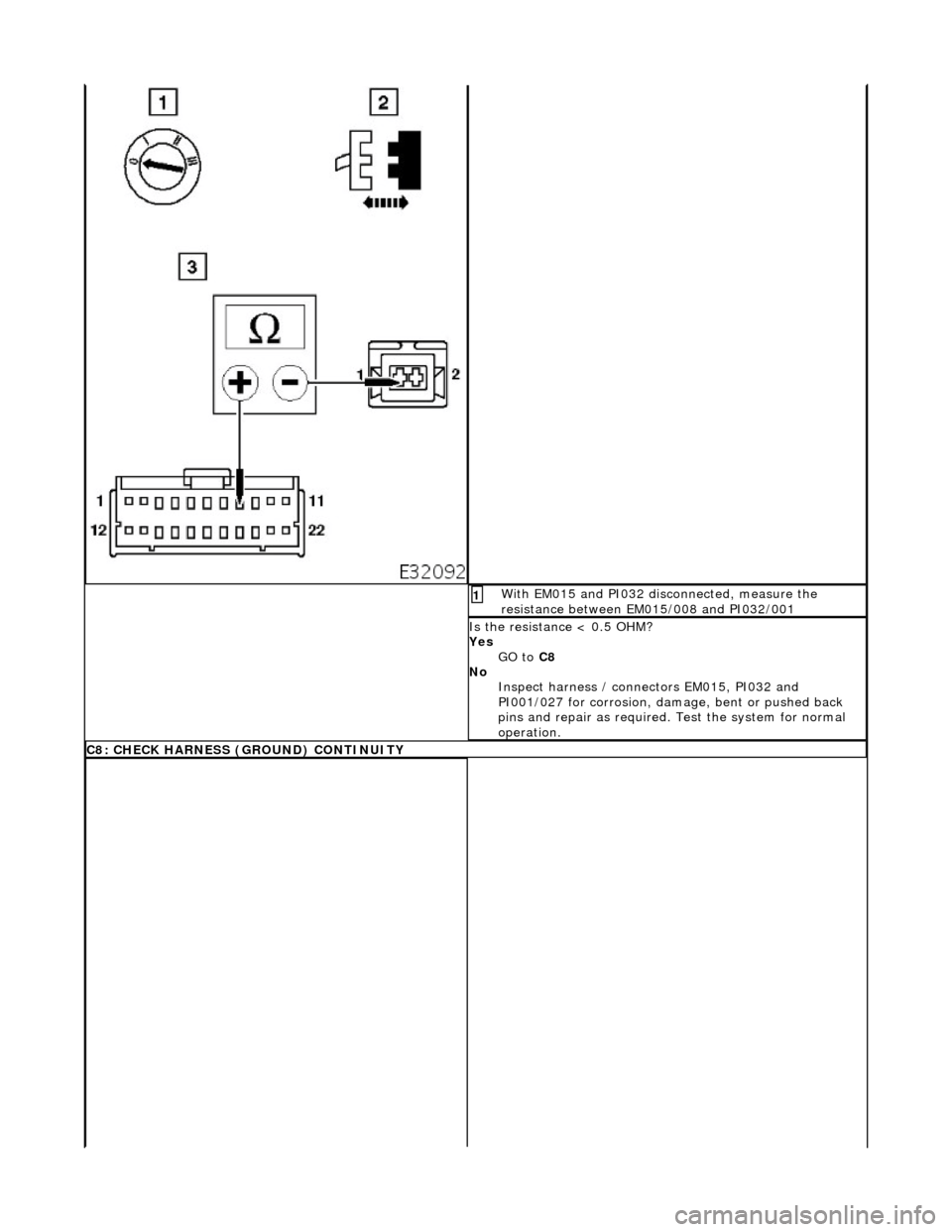
Wi
th EM015 and PI032 disconnected, measure the
resistance between EM015/008 and PI032/001
1
I s
the resistance < 0.5 OHM?
Yes GO to C8
No Inspect harness / connectors EM015, PI032 and
PI001/027 for corrosion, damage , bent or pushed back
pins and repair as required. Test the system for normal
operation.
C8 : CH
ECK HARNESS (GROUND) CONTINUITY
Page 547 of 2490
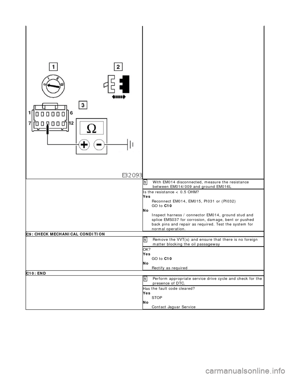
W
ith EM014 disconnected, measure the resistance
between EM014/009 and ground EM016L
1
I
s the resistance < 0.5 OHM?
Yes Reconnect EM014, EM015, PI031 or (PI032)
GO to C10
No Inspect harness / connector EM014, ground stud and
splice EMS037 for corrosion, damage, bent or pushed
back pins and repair as required. Test the system for
normal operation.
C9
: CHECK MECHANICAL CONDITION
R
emove the VVT(s) and ensure
that there is no foreign
matter blocking the oil passageway
1
OK
?
Yes GO to C10
No Rectify as required
C
10: END
Perform
appropriate service drive cycle and check for the
presence of DTC.
1
Has
the fault code cleared?
Yes STOP
No Contact Jaguar Service
Page 548 of 2490
En
gine - Valve Clea
rance Adjustment
Gene
ral Procedures
S
p
ecial Tool(s)
Tappet adjustment
3
03-
540
Ai
r gun, fan nozzl
e
303-590
1. Open the engine compartment and fit paintwork protection
sheets. Open to the service position.
2. Carefully remove both engine covers, taking care not to
damage the plasti c fixings or the rubber inserts.
3. Disc
onnect the batt
ery ground cable.
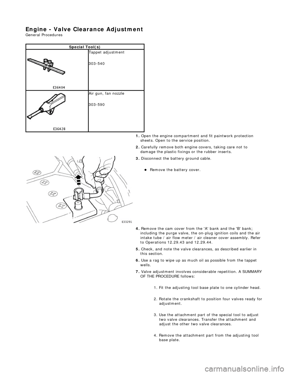
Re
move the battery cover.
4. Remove the cam cover from the 'A' bank and the 'B' bank;
including the purge valve, the on-plug ignition coils and the air
intake tube / air flow meter / air cleaner cover assembly. Refer
to Operations 12.29.43 and 12.29.44.
5. Check, and note the valve cleara nces, as described earlier in
this section.
6. Use a rag to wipe up as much oil as possible from the tappet
wells.
7. Valve adjustment involves considerable repetition. A SUMMARY
OF THE PROCEDURE follows:
1. Fit the adjusting tool base plate to one cylinder head.
2. Rotate the crankshaft to position four valves ready for
adjustment.
3. Use the attachment part of the special tool to adjust two valve clearances. Transfer the attachment and
adjust the other two valve clearances.
4. Remove the attachment pa rt from the adjusting tool
base plate.
Page 549 of 2490
5.
Repeat steps 2 to 4 three
more times until all sixteen
valves on the first cylinder head have been adjusted.
6. Repeat steps 1 to 5 for the other cylinder head.
7. Remove all equipment and reassemble the engine.
8. The following instructions describe the PROCEDURE FOR
ADJUSTING THE VALVE CLEARANCES.
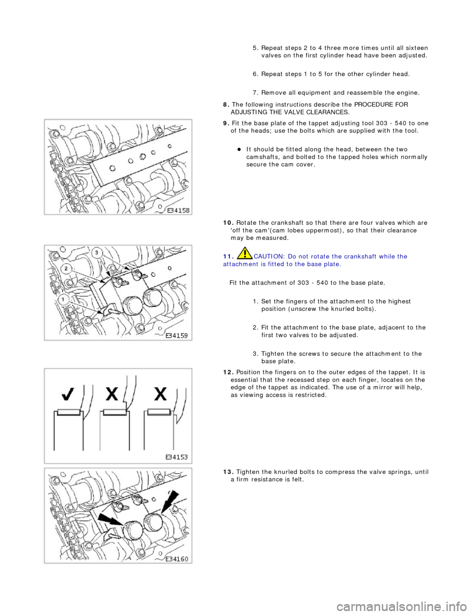
9. F
it the base plate of the tappet
adjusting tool 303 - 540 to one
of the heads; use the bolts which are supplied with the tool.
It
should be fitted along the head, between the two
camshafts, and bolted to the tapped holes which normally
secure the cam cover.
10. Rotate the crankshaft so that there are four valves which are
'off the cam'(cam lobes uppermos t), so that their clearance
may be measured.
11
.
CAUTION: Do not rotate the crankshaft while the
attachment is fitted to the base plate.
Fit the attachment of 303 - 540 to the base plate. 1. Set the fingers of the attachment to the highest position (unscrew the knurled bolts).
2. Fit the attachment to the base plate, adjacent to the first two valves to be adjusted.
3. Tighten the screws to secure the attachment to the base plate.
12
.
Position the fingers on to the outer edges of the tappet. It is
essential that the recessed step on each finger, locates on the
edge of the tappet as indicated. The use of a mirror will help,
as viewing access is restricted.
13
.
Tighten the knurled bolts to compress the valve springs, until
a firm resistan ce is felt.
Page 550 of 2490
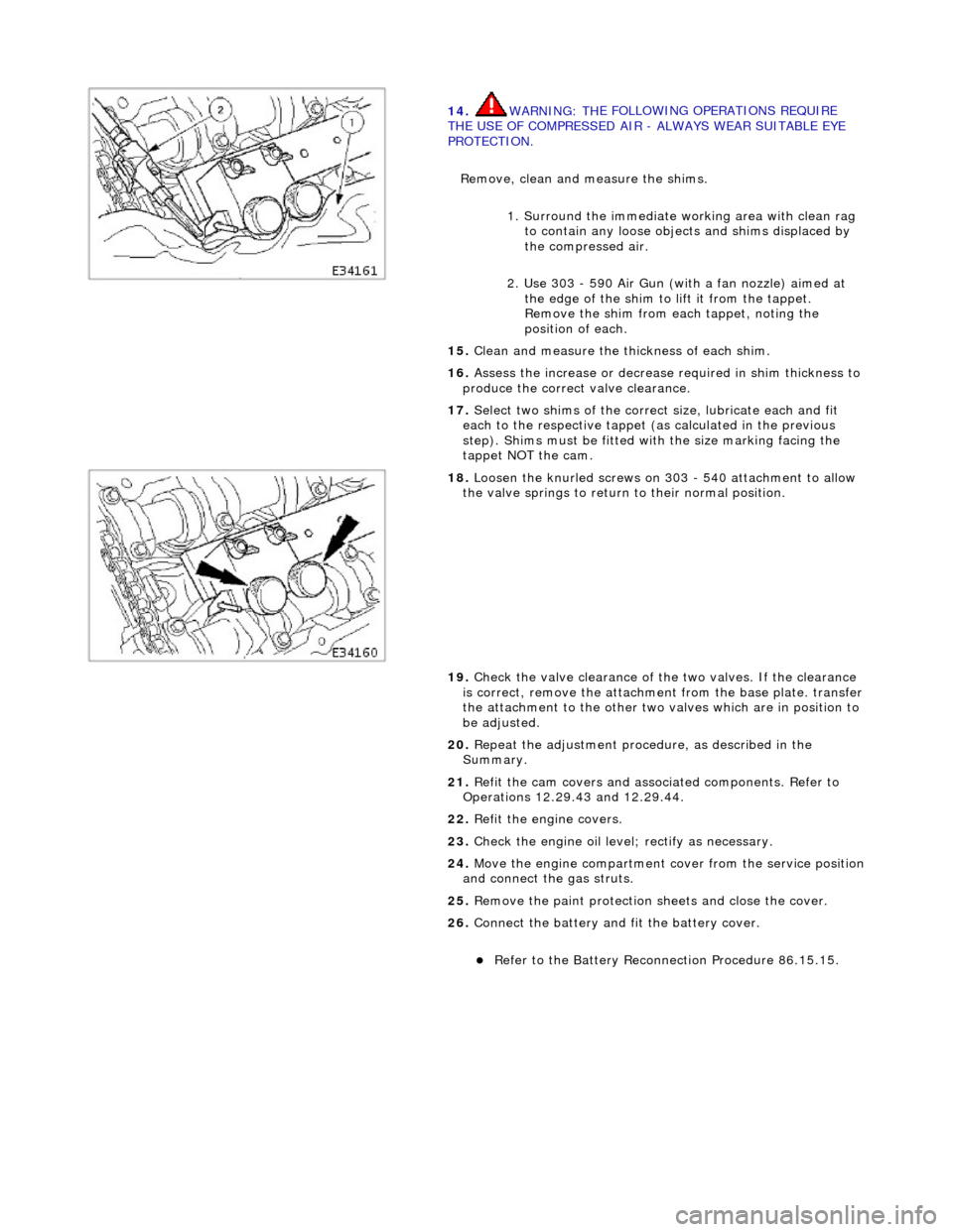
14
. WARNING: TH
E FOLLOWING OPERATIONS REQUIRE
THE USE OF COMPRESSED AIR - ALWAYS WEAR SUITABLE EYE
PROTECTION.
Remove, clean and measure the shims.
1. Surround the immediate wo rking area with clean rag
to contain any loose objects and shims displaced by
the compressed air.
2. Use 303 - 590 Air Gun (with a fan nozzle) aimed at the edge of the shim to lift it from the tappet.
Remove the shim from each tappet, noting the
position of each.
15 . Cl
ean and measure the thickness of each shim.
16. Assess the increase or decrease required in shim thickness to
produce the correct valve clearance.
17. Select two shims of the correct size, lubricate each and fit
each to the respective tappet (as calculated in the previous
step). Shims must be fitted with the size marking facing the
tappet NOT the cam.
18 . Loos
en the knurled screws on 303 - 540 attachment to allow
the valve springs to return to their normal position.
19. Check the valve clearance of the two valves. If the clearance
is correct, remove the attachment from the base plate. transfer
the attachment to the other two valves which are in position to
be adjusted.
20. Repeat the adjustment procedure, as described in the
Summary.
21. Refit the cam covers and associated components. Refer to
Operations 12.29.43 and 12.29.44.
22. Refit the engine covers.
23. Check the engine oil level; rectify as necessary.
24. Move the engine compartment cover from the service position
and connect the gas struts.
25. Remove the paint protection sheets and close the cover.
26. Connect the battery and fit the battery cover.
Refe
r to the Battery Reconnection Procedure 86.15.15.