JAGUAR XFR 2010 1.G Workshop Manual
Manufacturer: JAGUAR, Model Year: 2010, Model line: XFR, Model: JAGUAR XFR 2010 1.GPages: 3039, PDF Size: 58.49 MB
Page 1531 of 3039
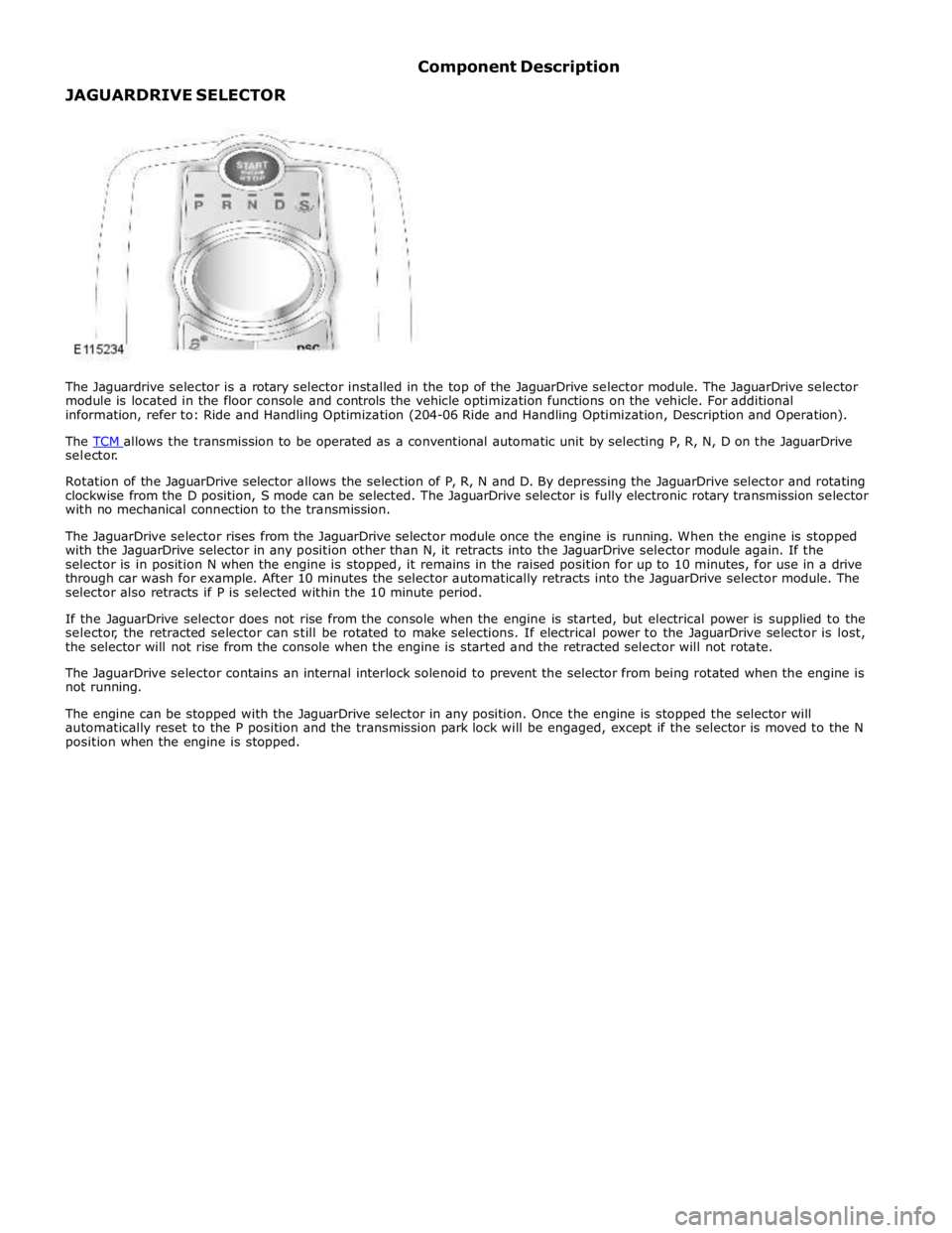
selector.
Rotation of the JaguarDrive selector allows the selection of P, R, N and D. By depressing the JaguarDrive selector and rotating
clockwise from the D position, S mode can be selected. The JaguarDrive selector is fully electronic rotary transmission selector
with no mechanical connection to the transmission.
The JaguarDrive selector rises from the JaguarDrive selector module once the engine is running. When the engine is stopped
with the JaguarDrive selector in any position other than N, it retracts into the JaguarDrive selector module again. If the
selector is in position N when the engine is stopped, it remains in the raised position for up to 10 minutes, for use in a drive
through car wash for example. After 10 minutes the selector automatically retracts into the JaguarDrive selector module. The
selector also retracts if P is selected within the 10 minute period.
If the JaguarDrive selector does not rise from the console when the engine is started, but electrical power is supplied to the
selector, the retracted selector can still be rotated to make selections. If electrical power to the JaguarDrive selector is lost,
the selector will not rise from the console when the engine is started and the retracted selector will not rotate.
The JaguarDrive selector contains an internal interlock solenoid to prevent the selector from being rotated when the engine is
not running.
The engine can be stopped with the JaguarDrive selector in any position. Once the engine is stopped the selector will
automatically reset to the P position and the transmission park lock will be engaged, except if the selector is moved to the N
position when the engine is stopped.
Page 1532 of 3039
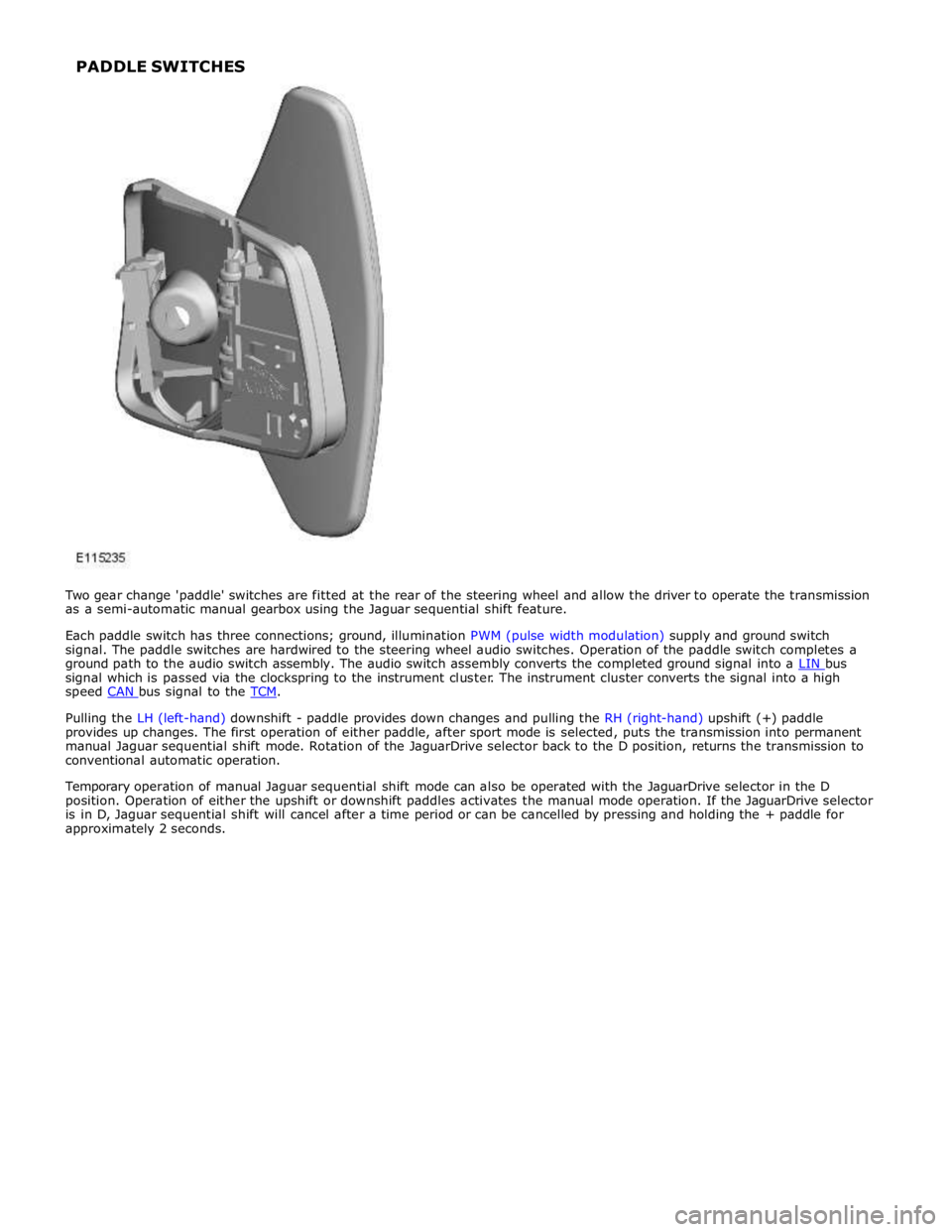
signal which is passed via the clockspring to the instrument cluster. The instrument cluster converts the signal into a high
speed CAN bus signal to the TCM.
Pulling the LH (left-hand) downshift - paddle provides down changes and pulling the RH (right-hand) upshift (+) paddle
provides up changes. The first operation of either paddle, after sport mode is selected, puts the transmission into permanent
manual Jaguar sequential shift mode. Rotation of the JaguarDrive selector back to the D position, returns the transmission to
conventional automatic operation.
Temporary operation of manual Jaguar sequential shift mode can also be operated with the JaguarDrive selector in the D
position. Operation of either the upshift or downshift paddles activates the manual mode operation. If the JaguarDrive selector
is in D, Jaguar sequential shift will cancel after a time period or can be cancelled by pressing and holding the + paddle for
approximately 2 seconds. PADDLE SWITCHES
Page 1533 of 3039
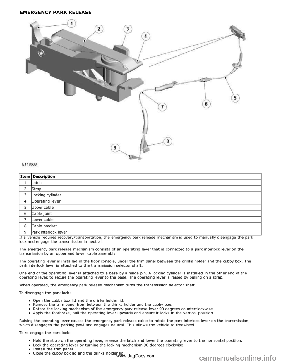
1 Latch 2 Strap 3 Locking cylinder 4 Operating lever 5 Upper cable 6 Cable joint 7 Lower cable 8 Cable bracket 9 Park interlock lever If a vehicle requires recovery/transportation, the emergency park release mechanism is used to manually disengage the park
lock and engage the transmission in neutral.
The emergency park release mechanism consists of an operating lever that is connected to a park interlock lever on the
transmission by an upper and lower cable assembly.
The operating lever is installed in the floor console, under the trim panel between the drinks holder and the cubby box. The
park interlock lever is attached to the transmission selector shaft.
One end of the operating lever is attached to a base by a hinge pin. A locking cylinder is installed in the other end of the
operating lever, to secure the operating lever to the base. The operating lever is raised by pulling on a strap.
When operated, the emergency park release mechanism turns the transmission selector shaft.
To disengage the park lock:
Open the cubby box lid and the drinks holder lid.
Remove the trim panel from between the drinks holder and the cubby box.
Rotate the locking mechanism of the emergency park release lever 90 degrees counterclockwise.
Apply the footbrake, pull the operating lever upwards and ensure it locks in the vertical position.
Raising the operating lever causes the emergency park release cable to rotate the park interlock lever on the transmission,
which disengages the parking pawl and engages neutral. This allows the vehicle to freewheel.
To re-engage the park lock:
Hold the strap on the operating lever, release the latch and lower the operating lever to the horizontal position.
Lock the operating lever by turning the locking mechanism 90 degrees clockwise.
Install the trim panel.
Close the cubby box lid and the drinks holder lid. www.JagDocs.com
Page 1534 of 3039
Published: 19-Jun-2013
Automatic Transmission/Transaxle External Controls - TDV6 3.0L Diesel /V8 5.0L Petrol/V8 S/C 5.0L Petrol - External Controls
Diagnosis and Testing
Principles of Operation
For a detailed description of the transmission external controls, refer to the relevant Description and Operation sections in the
workshop manual. REFER to: (307-05)
External Controls (Description and Operation),
External Controls (Description and Operation),
External Controls (Description and Operation).
Inspection and Verification
CAUTION: Diagnosis by substitution from a donor vehicle is NOT acceptable. Substitution of control modules does not
guarantee confirmation of a fault, and may also cause additional faults in the vehicle being tested and/or the donor vehicle.
1. Verify the customer concern.
2. Visually inspect for obvious signs of damage and system integrity.
Visual Inspection
Mechanical Electrical
Check for stuck/jammed switches and buttons
Visibly damaged or worn components
Loose or missing fasteners
Fuse(s)
Loose or corroded electrical connector(s)
Transmission control module
Transmission control switch
3. If an obvious cause for an observed or reported concern is found, correct the cause (if possible) before proceeding to
the next step.
4. If the cause is not visually evident, check for Diagnostic Trouble Codes (DTCs) and refer to the DTC Index.
DTC Index
For a list of DTCs that could be logged on this vehicle, please refer to Section 100-00.
REFER to: Diagnostic Trouble Code (DTC) Index - DTC: Transmission Control Module (TCM) (100-00, Description and Operation)
/
Diagnostic Trouble Code (DTC) Index - DTC: Transmission Control Switch (TCS) (100-00, Description and Operation).
Page 1535 of 3039
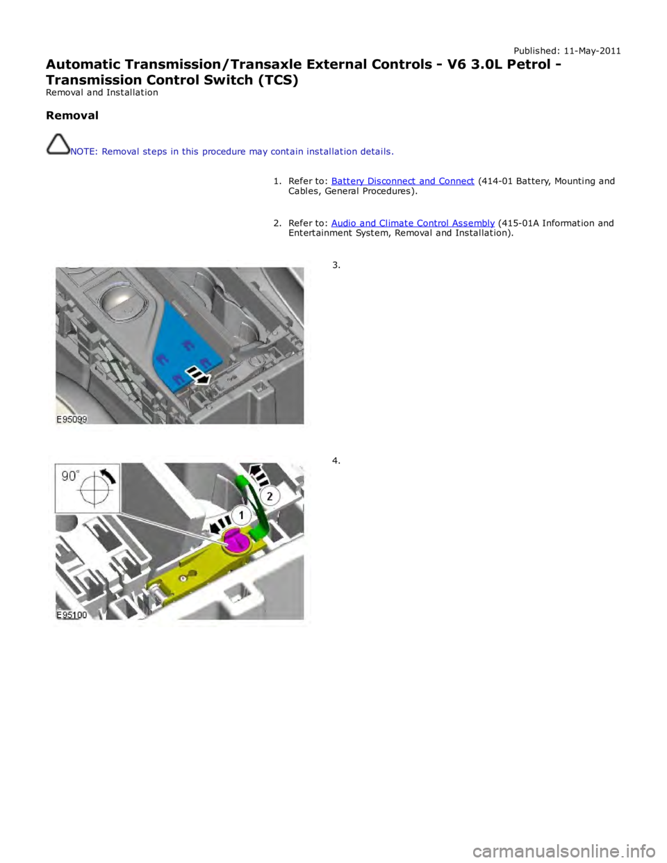
Published: 11-May-2011
Automatic Transmission/Transaxle External Controls - V6 3.0L Petrol -
Transmission Control Switch (TCS)
Removal and Installation
Removal
NOTE: Removal steps in this procedure may contain inst allation details.
Refer to: Batt ery Disconnect and Connect (414-01 Battery, Mounting and
Cables, General Procedures). 1.
Refer to: Audio and Climate Control Assembly (415-01A Informat ion and
Entert ainment Syst em, Removal and Installat ion). 2.3.4.
Page 1536 of 3039
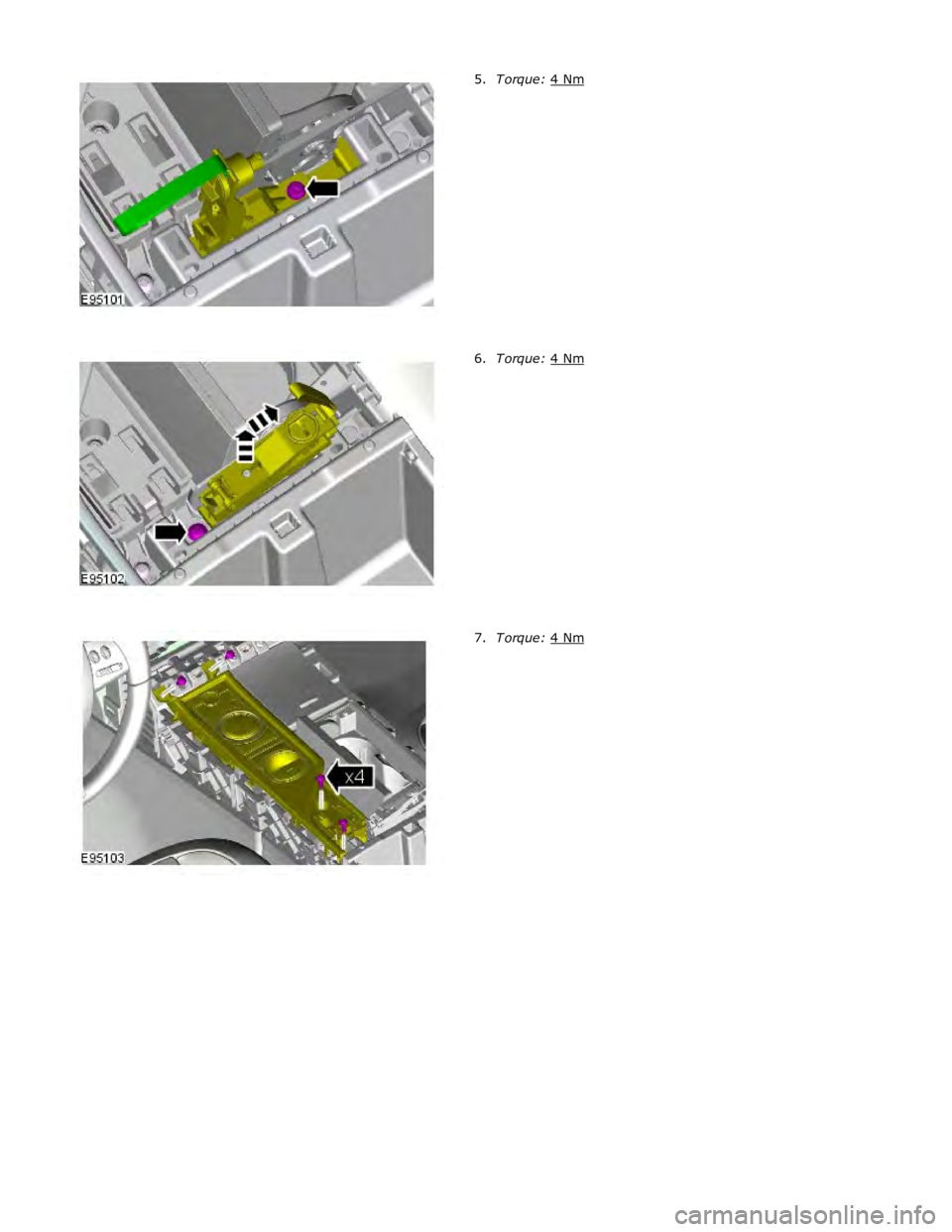
T orque: 4 Nm 5.T orque: 4 Nm 6.T orque: 4 Nm 7.
Page 1537 of 3039
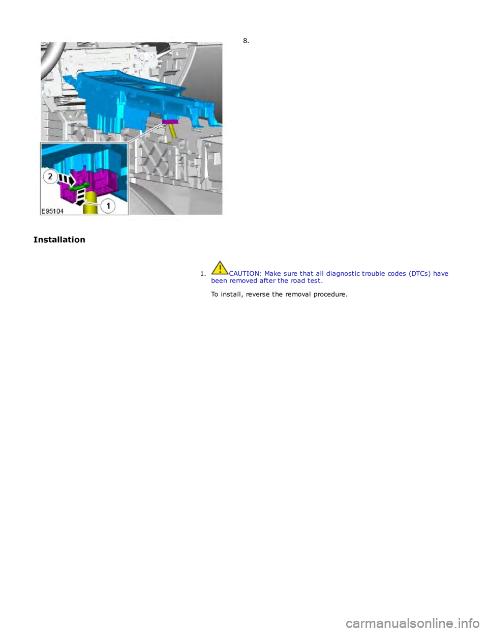
8.
Installation
CAUTION: Make sure t hat all diagnostic t rouble codes (DTCs) have
been removed after the road test.
To inst all, reverse t he removal procedure. 1.
Page 1538 of 3039

Published: 11-May-2011
Automatic Transmission/Transaxle External Controls - V6 3.0L Petrol -
Transmission Control Switch (TCS) Knob
Removal and Installation
Removal
NOTE: Removal steps in this procedure may contain inst allation details.
Start the engine and make sure that 'P' is selected.1.T orque: 2 Nm 2.
Installation
To inst all, reverse t he removal procedure. 1.www.JagDocs.com
Page 1539 of 3039

Published: 11-May-2011
Automatic Transmission/Transaxle External Controls - V6 3.0L Petrol -
Emergency Park Position Release Lever
Removal and Installation
Removal
NOTE: Removal steps in this procedure may contain inst allation details.
Refer to: Batt ery Disconnect and Connect (414-01 Battery, Mounting and
Cables, General Procedures). 1.
Refer to: Air Deflector (501-02, Removal and Installation). 2.
Refer to: Engine Rear Undershield (501-02 Front End Body Panels,
Removal and Installation). 3.
Refer to: Floor Console Side Trim Panel (501-12 Inst rument Panel and
Console, Removal and Installation). 4.WARNING: Make sure to support the vehicle with axle
stands.
T orque: 11 Nm 5.
Page 1540 of 3039
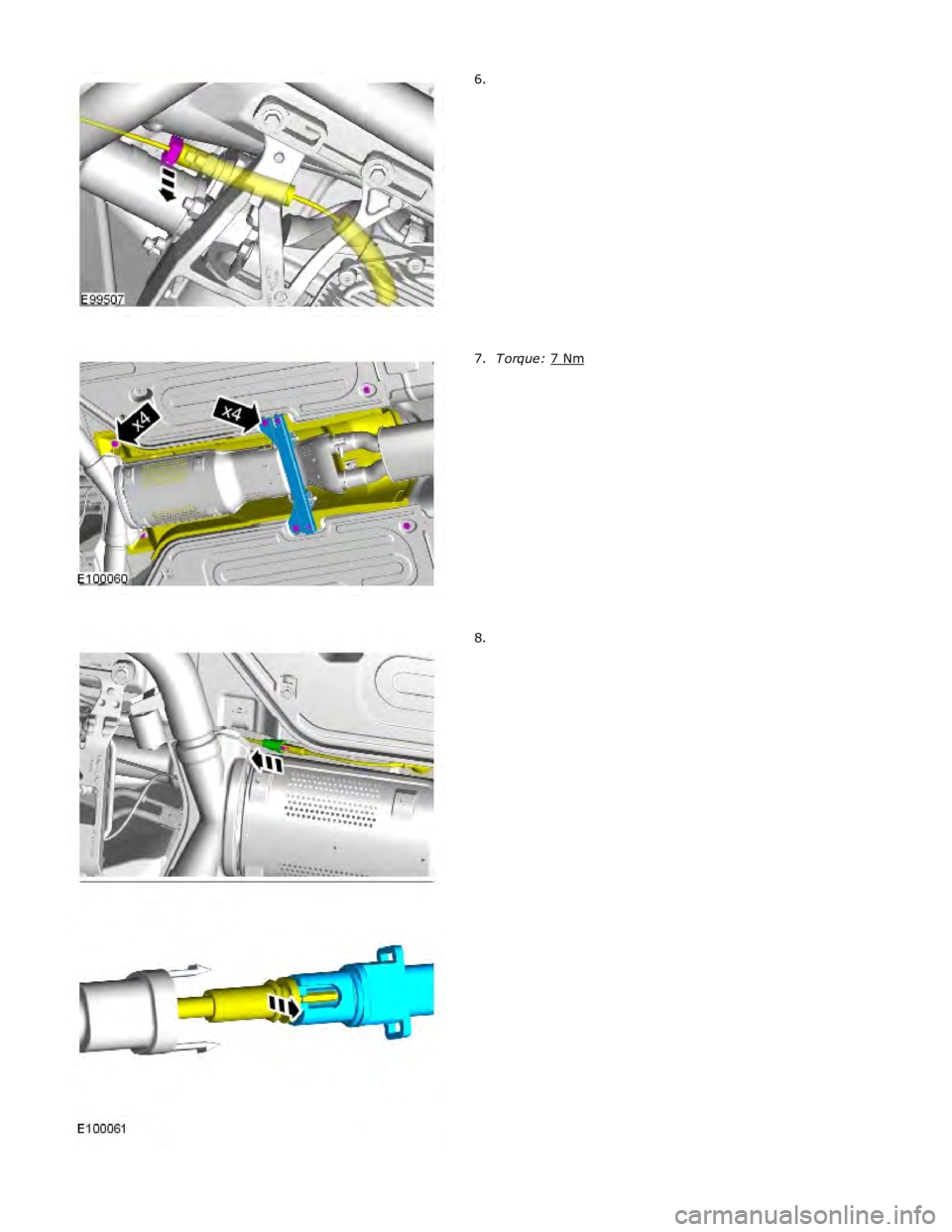
6.T orque: 7 Nm 7.8.