JAGUAR XFR 2010 1.G Workshop Manual
Manufacturer: JAGUAR, Model Year: 2010, Model line: XFR, Model: JAGUAR XFR 2010 1.GPages: 3039, PDF Size: 58.49 MB
Page 2981 of 3039
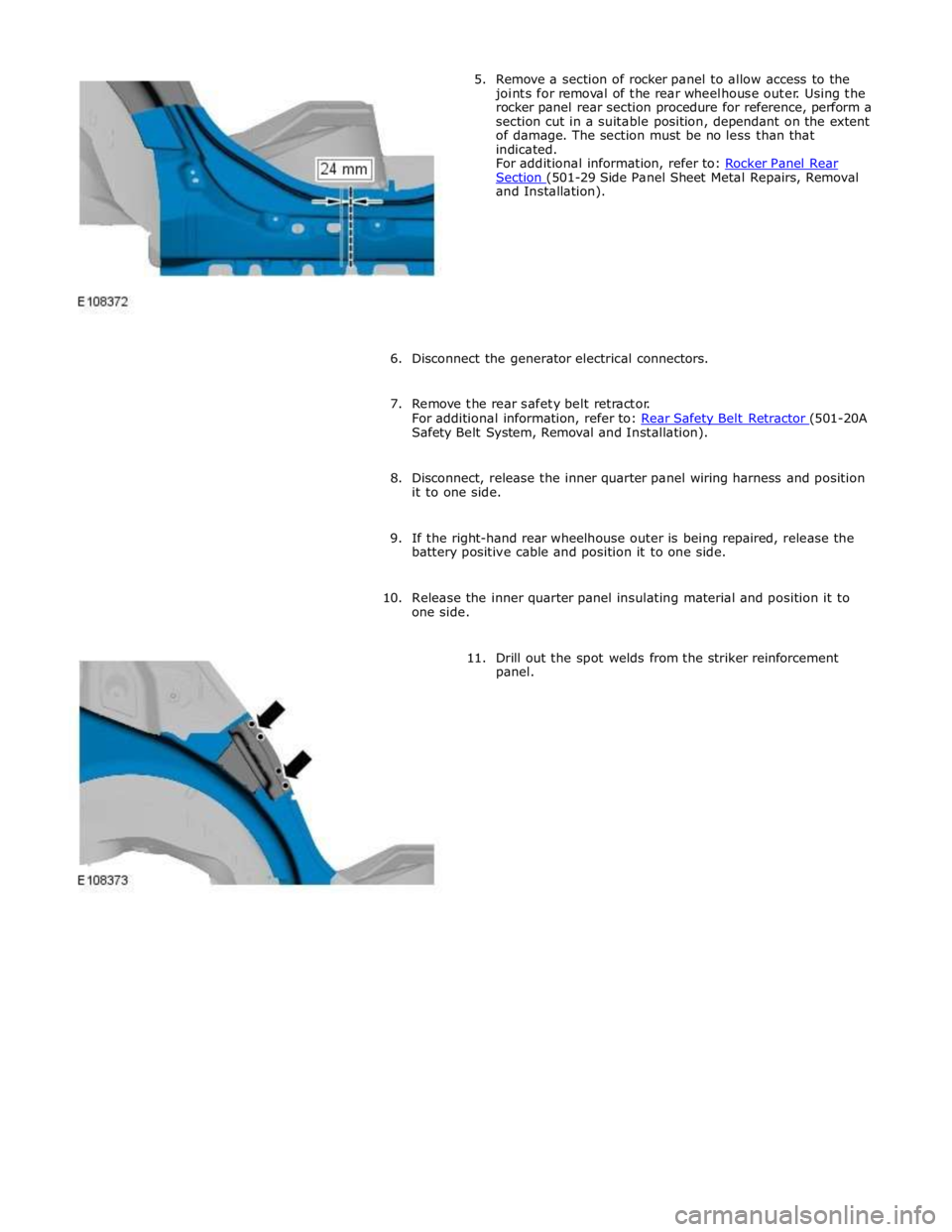
Section (501-29 Side Panel Sheet Metal Repairs, Removal and Installation).
6. Disconnect the generator electrical connectors.
7. Remove the rear safety belt retractor.
For additional information, refer to: Rear Safety Belt Retractor (501-20A Safety Belt System, Removal and Installation).
8. Disconnect, release the inner quarter panel wiring harness and position
it to one side.
9. If the right-hand rear wheelhouse outer is being repaired, release the
battery positive cable and position it to one side.
10. Release the inner quarter panel insulating material and position it to
one side.
11. Drill out the spot welds from the striker reinforcement
panel.
Page 2982 of 3039

12.
13.
14.
15. NOTE: A new striker reinforcement panel is supplied
on the quarter panel service panel.
Separate the joints, the adhesive and the NVH (noise,
vibration and harshness) component and remove the striker
reinforcement panel.
NOTE: Care should be taken when separating and
removing the ECM (engine control module) mounting
bracket if it is to be reused.
If the right-hand rear wheelhouse outer is to be repaired,
drill out the spot welds as indicated and remove the ECM
mounting bracket. Retain for reuse on installation.
NOTE: It is necessary to section the quarter panel
inner reinforcement at the point indicated, to make sure the
integrity of the safety belt anchorage point. The right-hand
panel is illustrated, the left-hand is similar.
Cut the quarter panel inner reinforcement, horizontally,
approximately 90mm from the centre of the safety belt bolt
anchorage point as indicated.
NOTE: The right-hand panel is illustrated, the
left-hand is similar although there are additional spot welds
to drill out.
Drill out the spot welds from the quarter panel inner
reinforcement section at the points indicated.
Page 2983 of 3039
16. NOTE: Retain the quarter panel inner reinforcement section as part
of this will be used as a template and to form a backing plate.
Separate the joints and remove the quarter panel inner reinforcement
section.
17.
18.
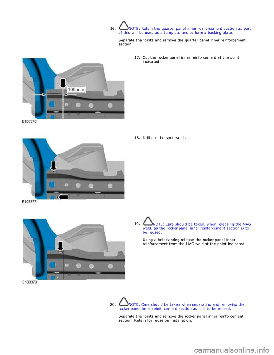
19. Cut the rocker panel inner reinforcement at the point
indicated.
Drill out the spot welds.
NOTE: Care should be taken, when releasing the MAG
weld, as the rocker panel inner reinforcement section is to
be reused.
Using a belt sander, release the rocker panel inner
reinforcement from the MAG weld at the point indicated.
20. NOTE: Care should be taken when separating and removing the
rocker panel inner reinforcement section as it is to be reused.
Separate the joints and remove the rocker panel inner reinforcement
section. Retain for reuse on installation.
Page 2984 of 3039
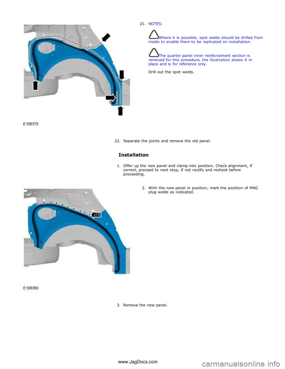
21. NOTES:
Where it is possible, spot welds should be drilled from
inside to enable them to be replicated on installation.
The quarter panel inner reinforcement section is
removed for this procedure, the illustration shows it in
place and is for reference only.
Drill out the spot welds.
22. Separate the joints and remove the old panel.
Installation
1. Offer up the new panel and clamp into position. Check alignment, if
correct, proceed to next step, if not rectify and recheck before
proceeding.
2. With the new panel in position, mark the position of MAG
plug welds as indicated.
3. Remove the new panel. www.JagDocs.com
Page 2985 of 3039
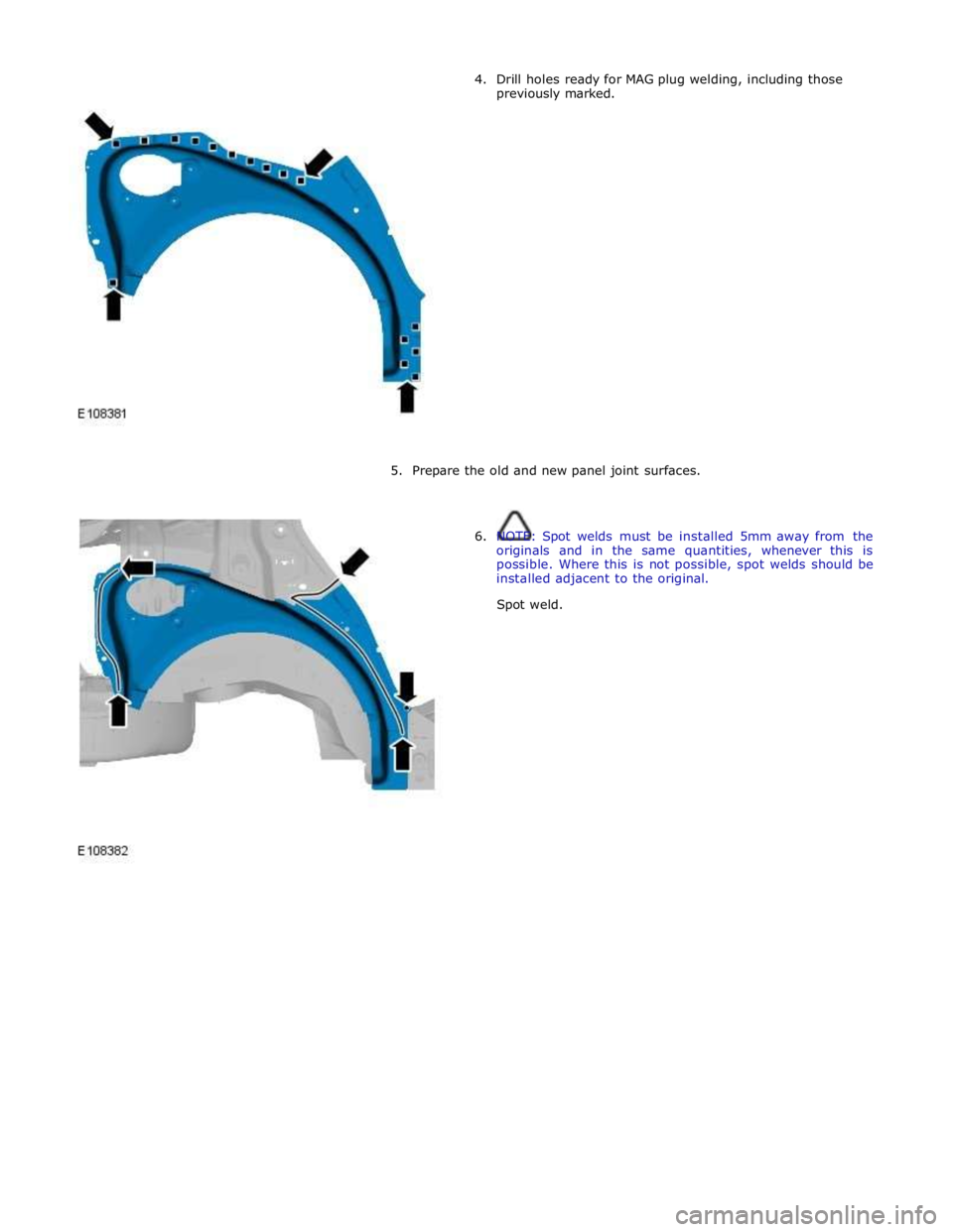
4. Drill holes ready for MAG plug welding, including those
previously marked.
5. Prepare the old and new panel joint surfaces.
6. NOTE: Spot welds must be installed 5mm away from the
originals and in the same quantities, whenever this is
possible. Where this is not possible, spot welds should be
installed adjacent to the original.
Spot weld.
Page 2986 of 3039
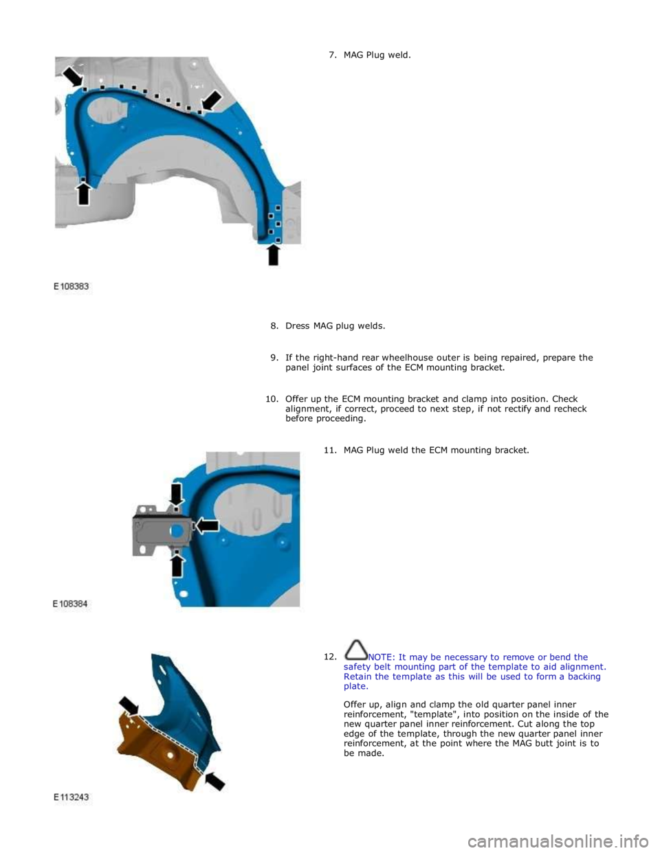
7. MAG Plug weld.
8. Dress MAG plug welds.
9. If the right-hand rear wheelhouse outer is being repaired, prepare the
panel joint surfaces of the ECM mounting bracket.
10. Offer up the ECM mounting bracket and clamp into position. Check
alignment, if correct, proceed to next step, if not rectify and recheck
before proceeding.
11.
12. MAG Plug weld the ECM mounting bracket.
NOTE: It may be necessary to remove or bend the
safety belt mounting part of the template to aid alignment.
Retain the template as this will be used to form a backing
plate.
Offer up, align and clamp the old quarter panel inner
reinforcement, "template", into position on the inside of the
new quarter panel inner reinforcement. Cut along the top
edge of the template, through the new quarter panel inner
reinforcement, at the point where the MAG butt joint is to
be made.
Page 2987 of 3039

13. Remove the template from the new quarter panel inner reinforcement.
14.
15. Cut and form a backing strip, a minimum of 40mm in width,
from the template as indicated.
NOTE: The backing strip should be positioned centrally
so that it will fit equally between the original and the new
quarter panel inner reinforcement sections, where the MAG
butt weld is to be performed.
Offer up the backing strip to the original quarter panel inner
reinforcement and clamp into position. Check alignment, if
correct, proceed to next step, if not rectify and recheck
before proceeding.
16. Remove the backing strip.
17. Drill holes in the original quarter panel inner reinforcement
ready for MAG plug welding as indicated.
18. Prepare the panel joint surfaces of the new and the original quarter
panel inner reinforcement and the backing strip.
19. Offer up the backing strip, align and clamp into position.
Page 2988 of 3039
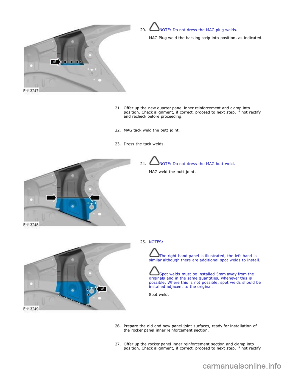
20. NOTE: Do not dress the MAG plug welds.
MAG Plug weld the backing strip into position, as indicated.
21. Offer up the new quarter panel inner reinforcement and clamp into
position. Check alignment, if correct, proceed to next step, if not rectify
and recheck before proceeding.
22. MAG tack weld the butt joint.
23. Dress the tack welds.
24.
25. NOTE: Do not dress the MAG butt weld.
MAG weld the butt joint.
NOTES:
The right-hand panel is illustrated, the left-hand is
similar although there are additional spot welds to install.
Spot welds must be installed 5mm away from the
originals and in the same quantities, whenever this is
possible. Where this is not possible, spot welds should be
installed adjacent to the original.
Spot weld.
26. Prepare the old and new panel joint surfaces, ready for installation of
the rocker panel inner reinforcement section.
27. Offer up the rocker panel inner reinforcement section and clamp into
position. Check alignment, if correct, proceed to next step, if not rectify
Page 2989 of 3039
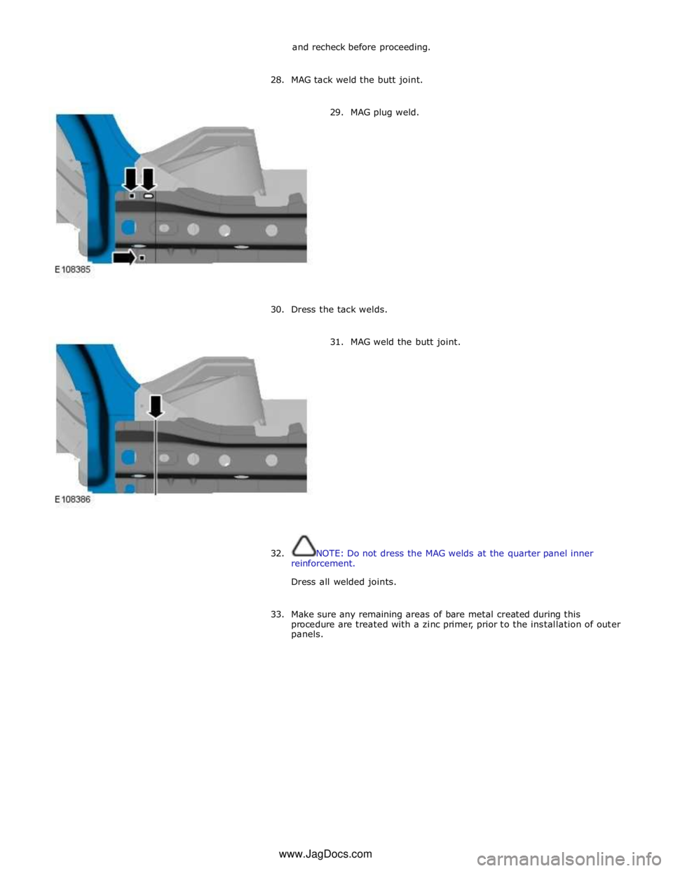
and recheck before proceeding.
28. MAG tack weld the butt joint.
29. MAG plug weld.
30.
Dress the tack welds.
31. MAG weld the butt joint.
32.
NOTE: Do not dress the MAG welds at the quarter panel inner
reinforcement.
Dress all welded joints.
33. Make sure any remaining areas of bare metal created during this
procedure are treated with a zinc primer, prior to the installation of outer
panels. www.JagDocs.com
Page 2990 of 3039
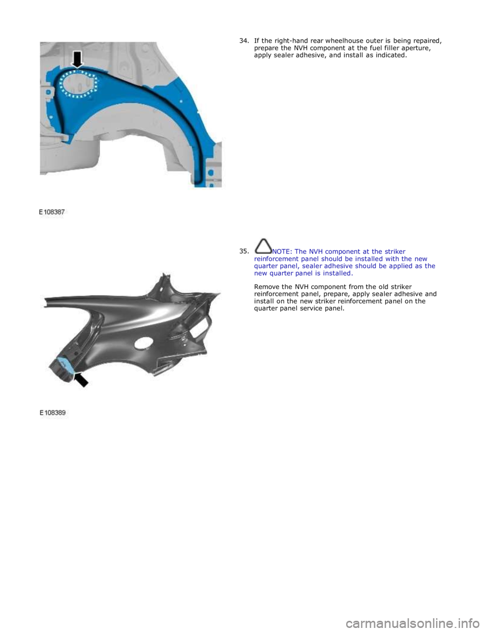
34.
35. If the right-hand rear wheelhouse outer is being repaired,
prepare the NVH component at the fuel filler aperture,
apply sealer adhesive, and install as indicated.
NOTE: The NVH component at the striker
reinforcement panel should be installed with the new
quarter panel, sealer adhesive should be applied as the
new quarter panel is installed.
Remove the NVH component from the old striker
reinforcement panel, prepare, apply sealer adhesive and
install on the new striker reinforcement panel on the
quarter panel service panel.