JAGUAR XFR 2010 1.G Workshop Manual
XFR 2010 1.G
JAGUAR
JAGUAR
https://www.carmanualsonline.info/img/21/7642/w960_7642-0.png
JAGUAR XFR 2010 1.G Workshop Manual
Trending: pinpoint, water pump, fuse diagram, coolant expansion tank, transmission oil, Control module, height adjustment
Page 2991 of 3039
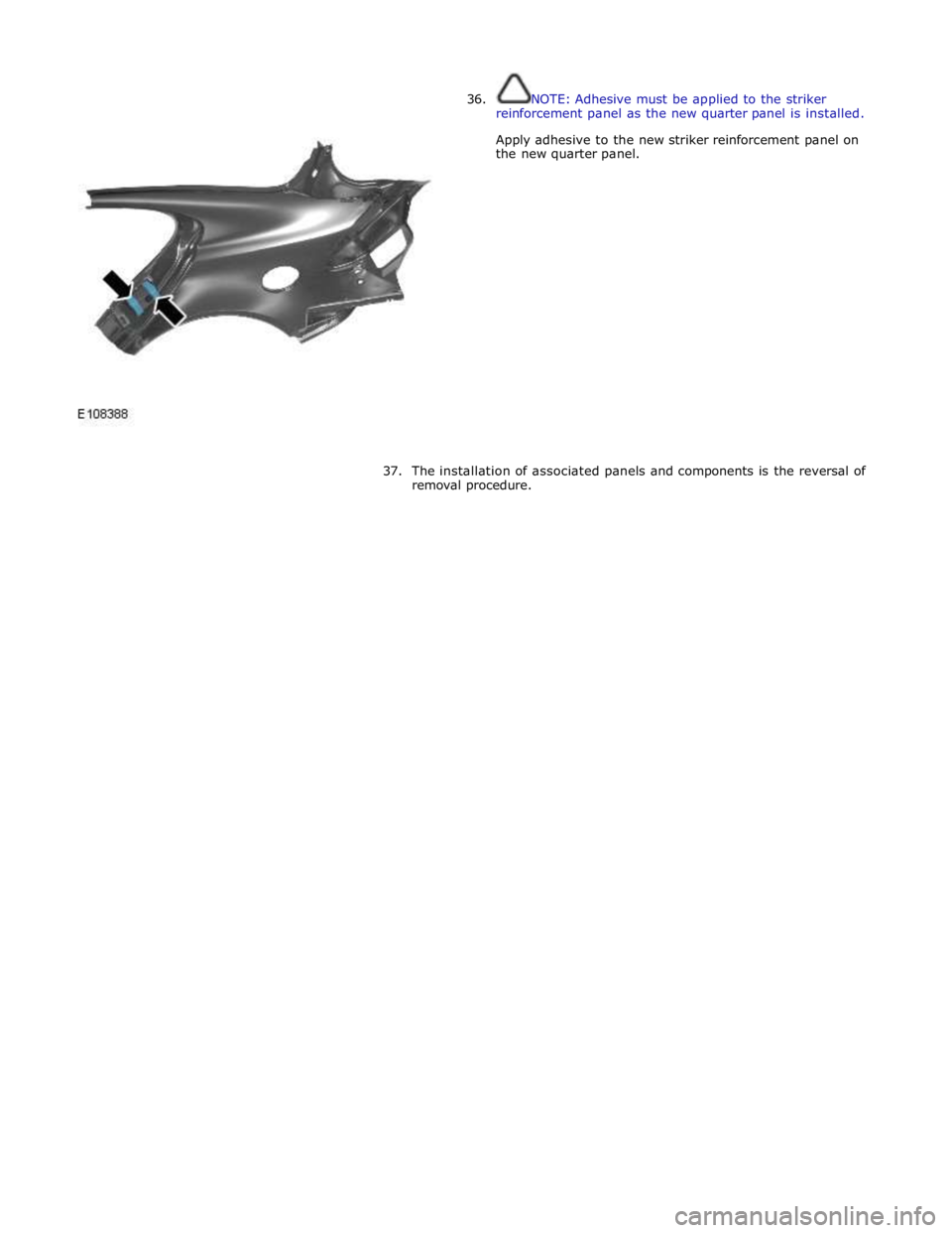
36. NOTE: Adhesive must be applied to the striker
reinforcement panel as the new quarter panel is installed.
Apply adhesive to the new striker reinforcement panel on
the new quarter panel.
37.
The installation of associated panels and components is the reversal of
removal procedure.
Page 2992 of 3039
Rear End Sheet Metal Repairs - Spare Wheel Well
Removal and Installation
Removal Published: 11-May-2011
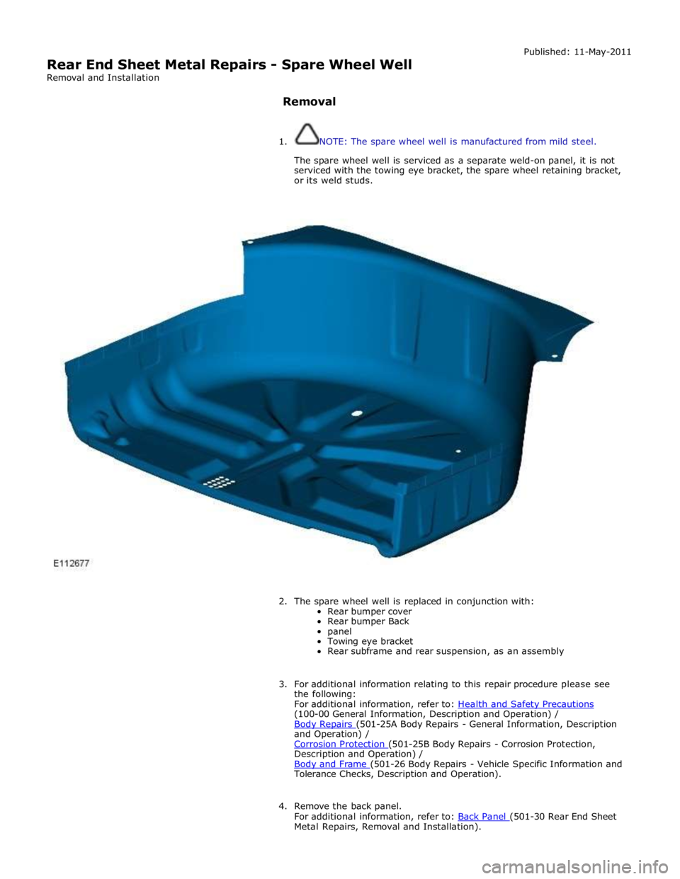
1. NOTE: The spare wheel well is manufactured from mild steel.
The spare wheel well is serviced as a separate weld-on panel, it is not
serviced with the towing eye bracket, the spare wheel retaining bracket,
or its weld studs.
2. The spare wheel well is replaced in conjunction with:
Rear bumper cover
Rear bumper Back
panel
Towing eye bracket
Rear subframe and rear suspension, as an assembly
3. For additional information relating to this repair procedure please see
the following:
For additional information, refer to: Health and Safety Precautions (100-00 General Information, Description and Operation) /
Body Repairs (501-25A Body Repairs - General Information, Description and Operation) /
Corrosion Protection (501-25B Body Repairs - Corrosion Protection, Description and Operation) /
Body and Frame (501-26 Body Repairs - Vehicle Specific Information and Tolerance Checks, Description and Operation).
4. Remove the back panel.
For additional information, refer to: Back Panel (501-30 Rear End Sheet Metal Repairs, Removal and Installation).
Page 2993 of 3039
5. Disconnect the generator electrical connectors.
6. Disconnect the battery positive cable and position it to one side.
7. Remove the rear subframe and rear suspension, as an assembly.
For additional information, refer to: Rear Subframe - V6 3.0L Petrol (502-00 Uni-Body, Subframe and Mounting System, Removal and
Installation).
8. Remove the fuel tank filler pipe.
For additional information, refer to: Fuel Tank Filler Pipe (310-01B,
Removal and Installation).
9. Release the left-hand and right-hand luggage floor wiring harnesses and
position them to one side.
10. Make sure that the rear seats are covered to prevent any damage during
this repair procedure.
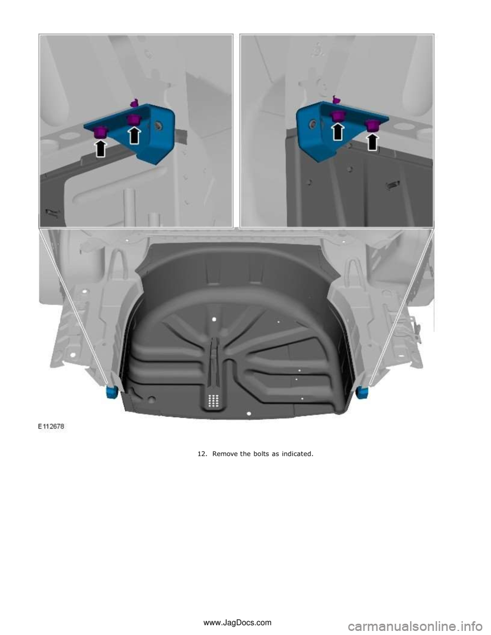
11. NOTE: If undamaged, the left-hand and right-hand rear bumper
retaining brackets should be reinstalled.
Remove the left-hand and right-hand rear bumper retaining brackets.
Page 2994 of 3039
Page 2995 of 3039
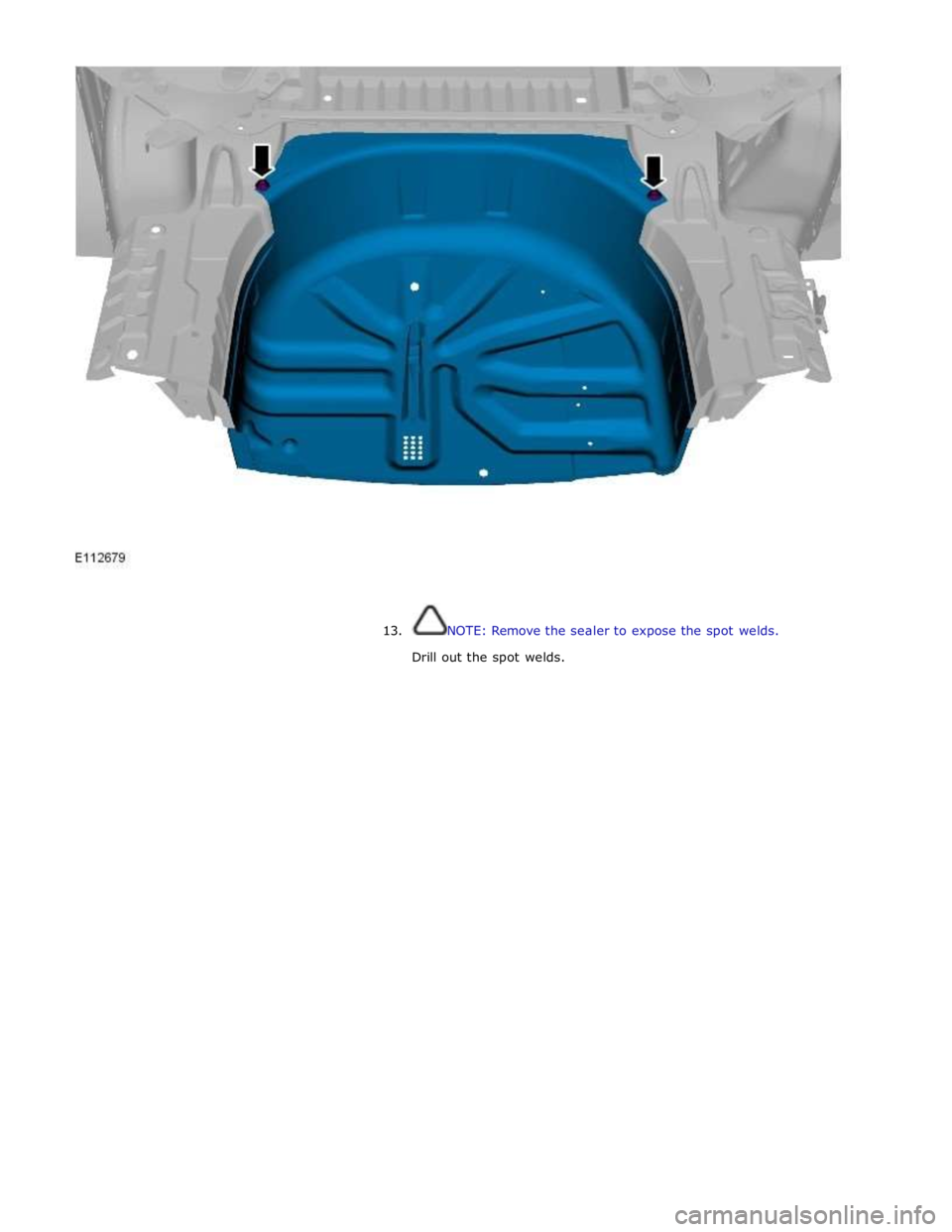
13. NOTE: Remove the sealer to expose the spot welds.
Drill out the spot welds.
Page 2996 of 3039
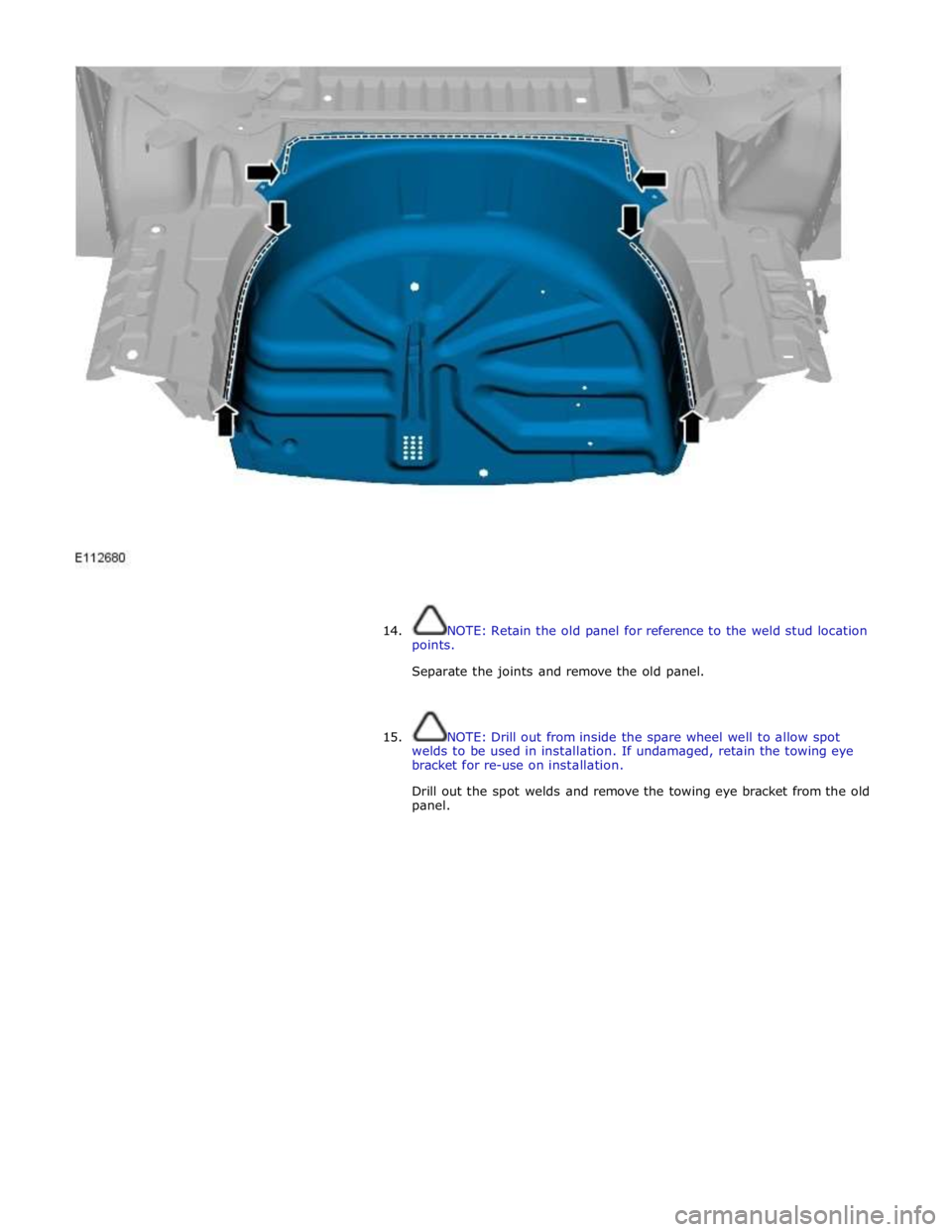
14. NOTE: Retain the old panel for reference to the weld stud location
points.
Separate the joints and remove the old panel.
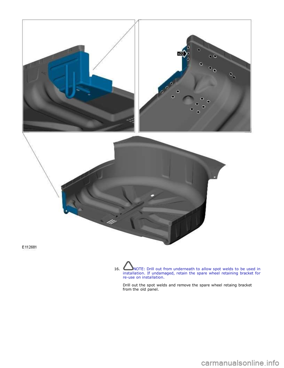
15. NOTE: Drill out from inside the spare wheel well to allow spot
welds to be used in installation. If undamaged, retain the towing eye
bracket for re-use on installation.
Drill out the spot welds and remove the towing eye bracket from the old
panel.
Page 2997 of 3039
16. NOTE: Drill out from underneath to allow spot welds to be used in
installation. If undamaged, retain the spare wheel retaining bracket for
re-use on installation.
Drill out the spot welds and remove the spare wheel retaing bracket
from the old panel.
Page 2998 of 3039
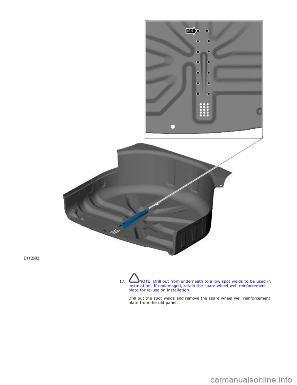
17. NOTE: Drill out from underneath to allow spot welds to be used in
installation. If undamaged, retain the spare wheel well reinforcement
plate for re-use on installation.
Drill out the spot welds and remove the spare wheel well reinforcement
plate from the old panel.
Page 2999 of 3039
Page 3000 of 3039
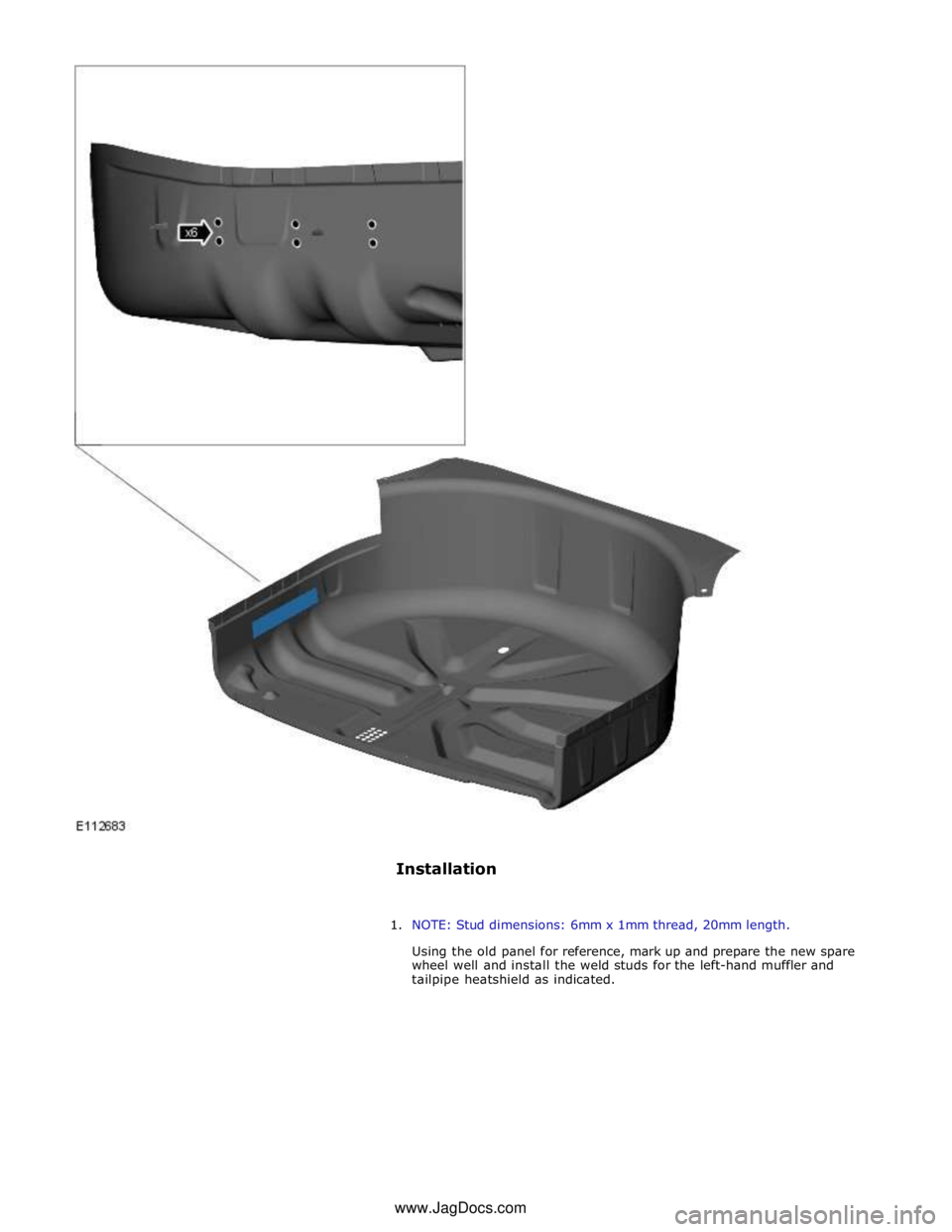
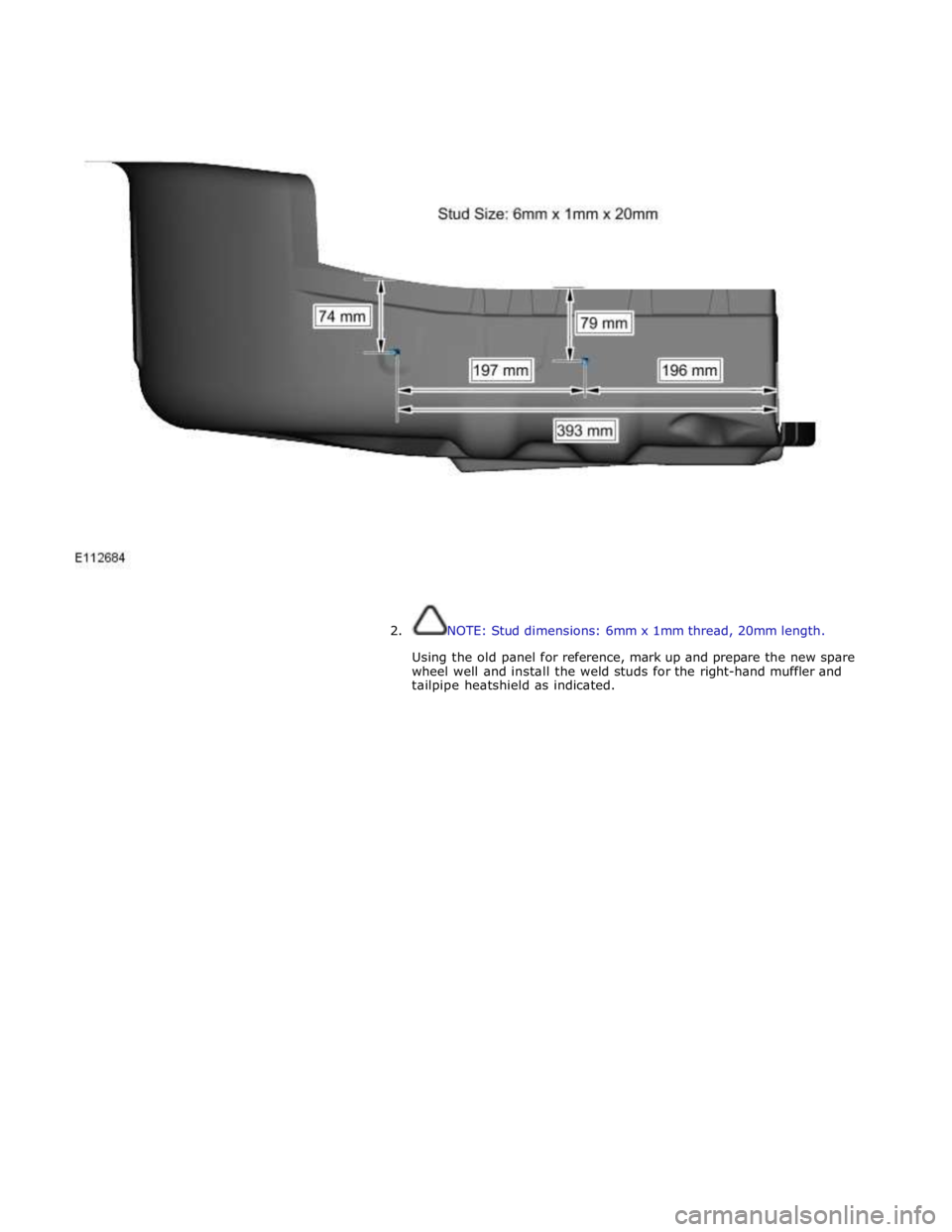
2. NOTE: Stud dimensions: 6mm x 1mm thread, 20mm length.
Using the old panel for reference, mark up and prepare the new spare
wheel well and install the weld studs for the right-hand muffler and
tailpipe heatshield as indicated.
Trending: b115913, wheel, U0404-68, wiring, remote control, B1B33-87, low oil pressure
