LAND ROVER FREELANDER 2001 Workshop Manual
Manufacturer: LAND ROVER, Model Year: 2001, Model line: FREELANDER, Model: LAND ROVER FREELANDER 2001Pages: 1007, PDF Size: 23.47 MB
Page 881 of 1007
HEATING AND VENTILATION
80-16REPAIRS
Relay - power - positive temperature co-
efficient (PTC) - Td4 models
$% 80.20.34
Remove
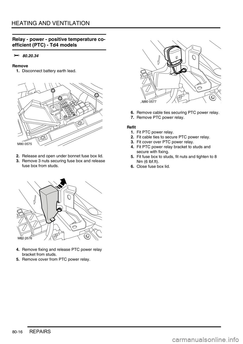
1.Disconnect battery earth lead.
2.Release and open under bonnet fuse box lid.
3.Remove 3 nuts securing fuse box and release
fuse box from studs.
4.Remove fixing and release PTC power relay
bracket from studs.
5.Remove cover from PTC power relay.6.Remove cable ties securing PTC power relay.
7.Remove PTC power relay.
Refit
1.Fit PTC power relay.
2.Fit cable ties to secure PTC power relay.
3.Fit cover over PTC power relay.
4.Fit PTC power relay bracket to studs and
secure with fixing.
5.Fit fuse box to studs, fit nuts and tighten to 8
Nm (6 lbf.ft).
6.Close fuse box lid.
M80 0576
M80 0577
Page 882 of 1007
HEATING AND VENTILATION
REPAIRS 80-17
Relay - control - positive temperature co-
efficient (PTC) - Td4 models
$% 80.20.35
Remove
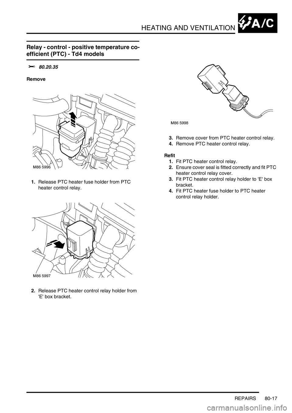
1.Release PTC heater fuse holder from PTC
heater control relay.
2.Release PTC heater control relay holder from
'E' box bracket.3.Remove cover from PTC heater control relay.
4.Remove PTC heater control relay.
Refit
1.Fit PTC heater control relay.
2.Ensure cover seal is fitted correctly and fit PTC
heater control relay cover.
3.Fit PTC heater control relay holder to 'E' box
bracket.
4.Fit PTC heater fuse holder to PTC heater
control relay holder.
Page 883 of 1007
HEATING AND VENTILATION
80-18REPAIRS
Fuel burning heater (FBH)
$% 80.40.01
Remove
1.Disconnect battery earth lead.
2.Remove front bumper.
+ EXTERIOR FITTINGS, REPAIRS,
Bumper - assembly - front - up to 04MY.
3.Drain coolant.
+ COOLING SYSTEM - Td4,
ADJUSTMENTS, Coolant - drain and refill.
4.Position container to collect coolant spillage.
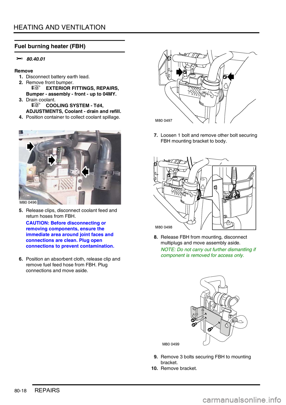
5.Release clips, disconnect coolant feed and
return hoses from FBH.
CAUTION: Before disconnecting or
removing components, ensure the
immediate area around joint faces and
connections are clean. Plug open
connections to prevent contamination.
6.Position an absorbent cloth, release clip and
remove fuel feed hose from FBH. Plug
connections and move aside.7.Loosen 1 bolt and remove other bolt securing
FBH mounting bracket to body.
8.Release FBH from mounting, disconnect
multiplugs and move assembly aside.
NOTE: Do not carry out further dismantling if
component is removed for access only.
9.Remove 3 bolts securing FBH to mounting
bracket.
10.Remove bracket.
M80 0496
M80 0499
Page 884 of 1007

HEATING AND VENTILATION
REPAIRS 80-19
11.Release clip securing air intake hose to FBH,
release clamp from exhaust manifold.
12.Remove 2 bolts securing air intake and exhaust
assembly to FBH and move aside.
Refit
1.Fit exhaust pipe, air intake hose and bracket
assembly to FBH.
2.Fit and tighten bolts to 10 Nm (7.5 lbf.ft).
3.Tighten exhaust pipe clamp to 5 Nm (3.5 lbf.ft).
4.Align air intake hose with mark on casing and
secure with clip.
5.Fit mounting bracket to FBH and tighten bolts to
10 Nm (7.5 lbf.ft).
6.Connect multiplugs to FBH.
7.Fit FBH to body, tighten bolts to 10 Nm (7.5
lbf.ft).
8.Fit coolant hoses to FBH and secure with clips.
9.Fit fuel feed hose to FBH and secure with clip.
10.Refill cooling system.
+ COOLING SYSTEM - Td4,
ADJUSTMENTS, Coolant - drain and refill.
11.Fit front bumper.
+ EXTERIOR FITTINGS, REPAIRS,
Bumper - assembly - front - up to 04MY.
12.Connect battery earth lead.
Sensor - outside temperature (OT)
$% 80.40.31
Remove
1.Remove front bumper.
+ EXTERIOR FITTINGS, REPAIRS,
Bumper - assembly - front - up to 04MY.
2.Disconnect multiplug from OT sensor.
3.Remove OT sensor from mounting bracket,
collect rubber washer and spacer.
Refit
1.Clean OT mounting bracket and sensor.
2.Fit OT sensor to mounting bracket, fit rubber
washer and spacer, connect multiplug.
3.Fit front bumper.
+ EXTERIOR FITTINGS, REPAIRS,
Bumper - assembly - front - up to 04MY.
Page 885 of 1007
HEATING AND VENTILATION
80-20REPAIRS
Fuel pump - fuel burning heater - up to
03MY
$% 80.40.40
Remove
1.Disconnect battery earth lead.
2.Remove RH rear wheel arch liner.
+ EXTERIOR FITTINGS, REPAIRS,
Liner - rear wheel arch.
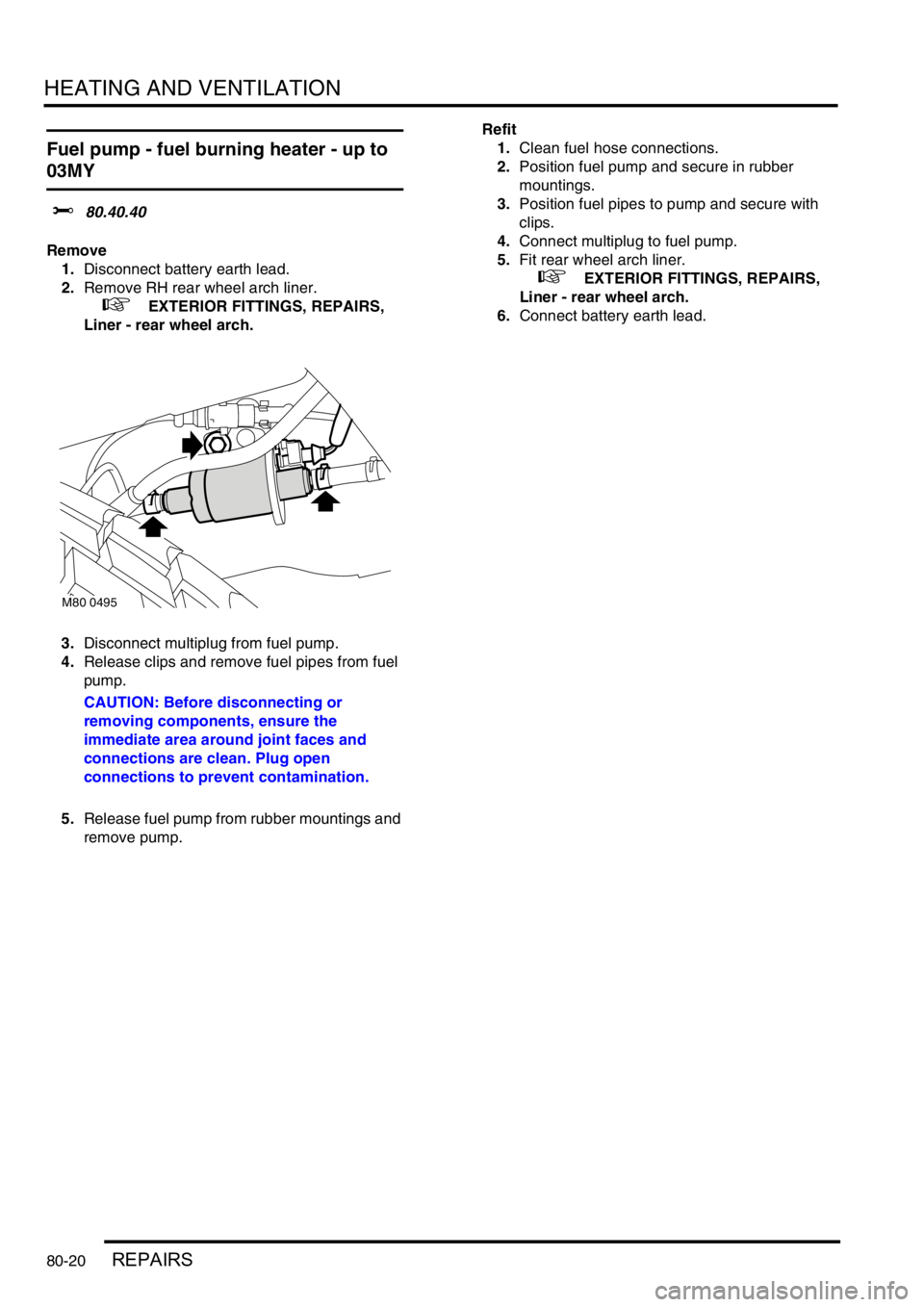
3.Disconnect multiplug from fuel pump.
4.Release clips and remove fuel pipes from fuel
pump.
CAUTION: Before disconnecting or
removing components, ensure the
immediate area around joint faces and
connections are clean. Plug open
connections to prevent contamination.
5.Release fuel pump from rubber mountings and
remove pump.Refit
1.Clean fuel hose connections.
2.Position fuel pump and secure in rubber
mountings.
3.Position fuel pipes to pump and secure with
clips.
4.Connect multiplug to fuel pump.
5.Fit rear wheel arch liner.
+ EXTERIOR FITTINGS, REPAIRS,
Liner - rear wheel arch.
6.Connect battery earth lead.
M80 0495
Page 886 of 1007
HEATING AND VENTILATION
REPAIRS 80-21
Fuel pump - fuel burning heater - from
03MY
$% 80.40.40
Remove
1.Disconnect battery earth lead.
WARNING: Fuel vapour is highly flammable
and in confined spaces is also explosive
and toxic. Always have a fire extinguisher
containing foam, CO
2, gas or powder close
at hand when handling or draining fuel.
2.Raise vehicle on lift.
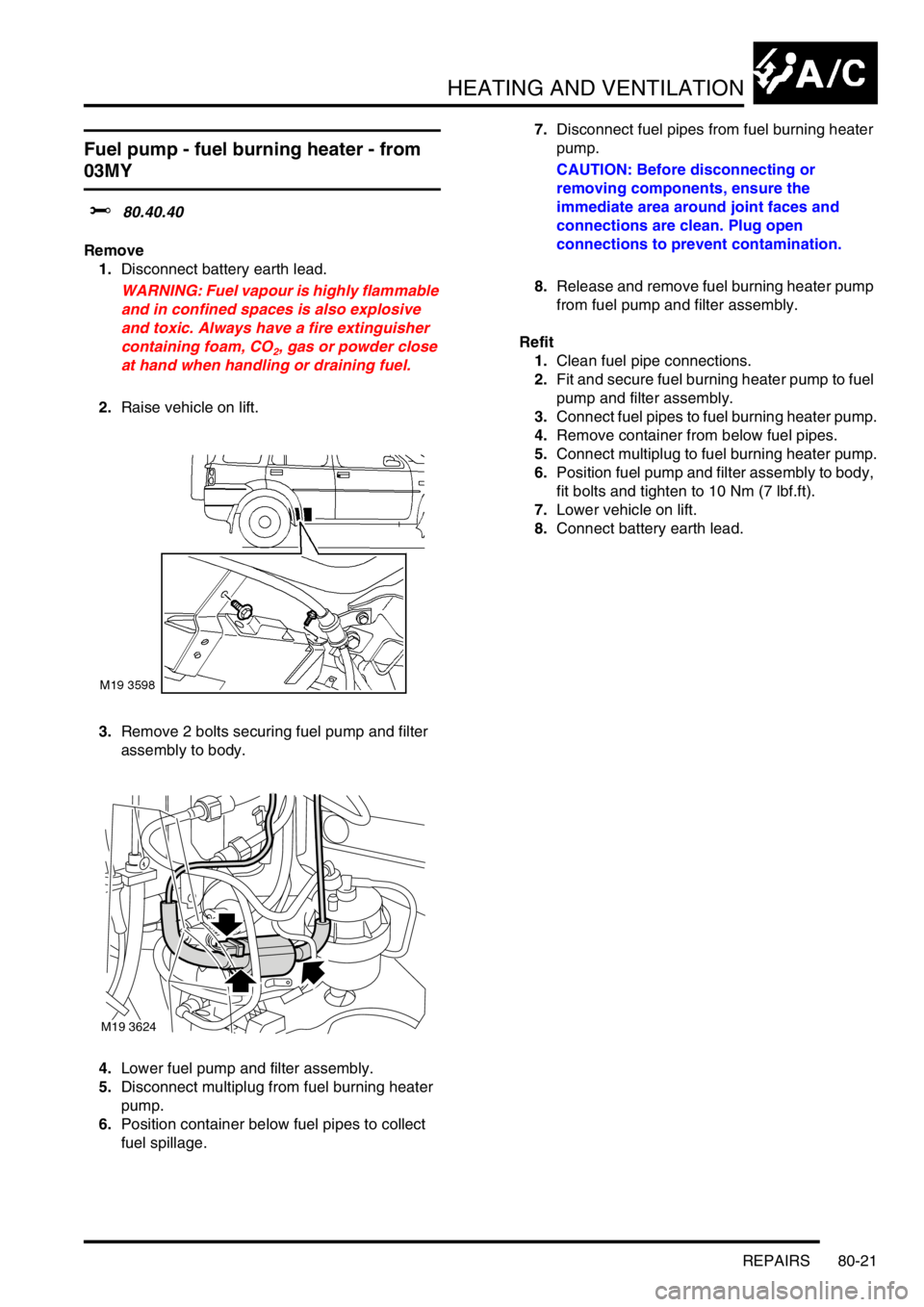
3.Remove 2 bolts securing fuel pump and filter
assembly to body.
4.Lower fuel pump and filter assembly.
5.Disconnect multiplug from fuel burning heater
pump.
6.Position container below fuel pipes to collect
fuel spillage.7.Disconnect fuel pipes from fuel burning heater
pump.
CAUTION: Before disconnecting or
removing components, ensure the
immediate area around joint faces and
connections are clean. Plug open
connections to prevent contamination.
8.Release and remove fuel burning heater pump
from fuel pump and filter assembly.
Refit
1.Clean fuel pipe connections.
2.Fit and secure fuel burning heater pump to fuel
pump and filter assembly.
3.Connect fuel pipes to fuel burning heater pump.
4.Remove container from below fuel pipes.
5.Connect multiplug to fuel burning heater pump.
6.Position fuel pump and filter assembly to body,
fit bolts and tighten to 10 Nm (7 lbf.ft).
7.Lower vehicle on lift.
8.Connect battery earth lead.
M19 3624
Page 887 of 1007

Page 888 of 1007
AIR CONDITIONING
REFRIGERANT RECOVERY, RECYCLING AND RECHARGING 82-1
AIR CONDITIONING REFRIGERANT RECOVERY, RECYCLING AND RECHARGING
Refrigerant recovery - recycling and
recharge
$% 82.30.02
Refrigerant recovery
WARNING: Servicing must only be carried
out by personnel familiar with both the
vehicle system and the charging and testing
equipment. All operations must be carried
out in a well ventilated area away from open
flame and heat sources.
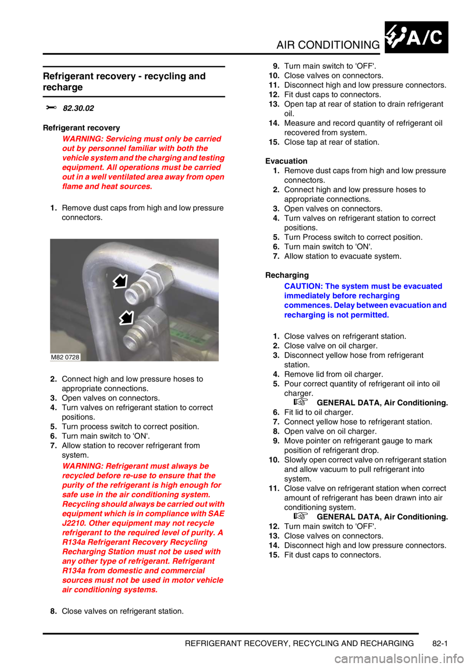
1.Remove dust caps from high and low pressure
connectors.
2.Connect high and low pressure hoses to
appropriate connections.
3.Open valves on connectors.
4.Turn valves on refrigerant station to correct
positions.
5.Turn process switch to correct position.
6.Turn main switch to 'ON'.
7.Allow station to recover refrigerant from
system.
WARNING: Refrigerant must always be
recycled before re-use to ensure that the
purity of the refrigerant is high enough for
safe use in the air conditioning system.
Recycling should always be carried out with
equipment which is in compliance with SAE
J2210. Other equipment may not recycle
refrigerant to the required level of purity. A
R134a Refrigerant Recovery Recycling
Recharging Station must not be used with
any other type of refrigerant. Refrigerant
R134a from domestic and commercial
sources must not be used in motor vehicle
air conditioning systems.
8.Close valves on refrigerant station.9.Turn main switch to 'OFF'.
10.Close valves on connectors.
11.Disconnect high and low pressure connectors.
12.Fit dust caps to connectors.
13.Open tap at rear of station to drain refrigerant
oil.
14.Measure and record quantity of refrigerant oil
recovered from system.
15.Close tap at rear of station.
Evacuation
1.Remove dust caps from high and low pressure
connectors.
2.Connect high and low pressure hoses to
appropriate connections.
3.Open valves on connectors.
4.Turn valves on refrigerant station to correct
positions.
5.Turn Process switch to correct position.
6.Turn main switch to 'ON'.
7.Allow station to evacuate system.
Recharging
CAUTION: The system must be evacuated
immediately before recharging
commences. Delay between evacuation and
recharging is not permitted.
1.Close valves on refrigerant station.
2.Close valve on oil charger.
3.Disconnect yellow hose from refrigerant
station.
4.Remove lid from oil charger.
5.Pour correct quantity of refrigerant oil into oil
charger.
+ GENERAL DATA, Air Conditioning.
6.Fit lid to oil charger.
7.Connect yellow hose to refrigerant station.
8.Open valve on oil charger.
9.Move pointer on refrigerant gauge to mark
position of refrigerant drop.
10.Slowly open correct valve on refrigerant station
and allow vacuum to pull refrigerant into
system.
11.Close valve on refrigerant station when correct
amount of refrigerant has been drawn into air
conditioning system.
+ GENERAL DATA, Air Conditioning.
12.Turn main switch to 'OFF'.
13.Close valves on connectors.
14.Disconnect high and low pressure connectors.
15.Fit dust caps to connectors.
M82 0728
Page 889 of 1007

Page 890 of 1007
AIR CONDITIONING
ADJUSTMENTS 82-3
ADJUST ME NTS
Drive belt - compressor - Td4
$% 82.10.01
Check
1.Disconnect battery earth lead.
2.Remove underbelly panel.
+ EXTERIOR FITTINGS, REPAIRS,
Panel - underbelly.
3.Turn steering on RH lock.
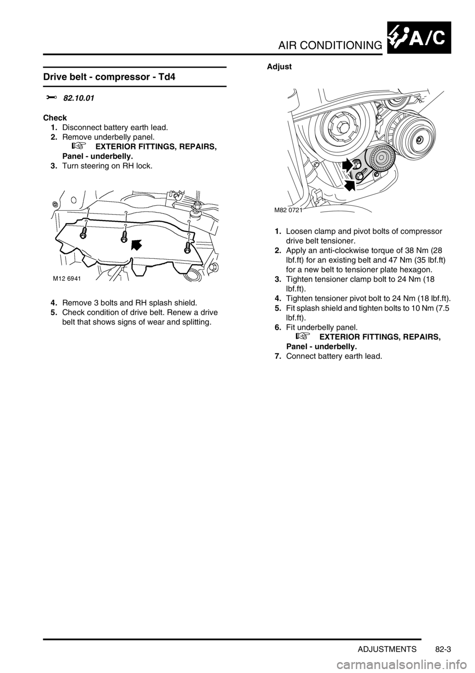
4.Remove 3 bolts and RH splash shield.
5.Check condition of drive belt. Renew a drive
belt that shows signs of wear and splitting.Adjust
1.Loosen clamp and pivot bolts of compressor
drive belt tensioner.
2.Apply an anti-clockwise torque of 38 Nm (28
lbf.ft) for an existing belt and 47 Nm (35 lbf.ft)
for a new belt to tensioner plate hexagon.
3.Tighten tensioner clamp bolt to 24 Nm (18
lbf.ft).
4.Tighten tensioner pivot bolt to 24 Nm (18 lbf.ft).
5.Fit splash shield and tighten bolts to 10 Nm (7.5
lbf.ft).
6.Fit underbelly panel.
+ EXTERIOR FITTINGS, REPAIRS,
Panel - underbelly.
7.Connect battery earth lead.
M82 0721