LAND ROVER FRELANDER 2 2006 Repair Manual
FRELANDER 2 2006
LAND ROVER
LAND ROVER
https://www.carmanualsonline.info/img/64/57251/w960_57251-0.png
LAND ROVER FRELANDER 2 2006 Repair Manual
Trending: four wheel drive, dimensions, CD changer, fuel fill door release, service interval reset, engine oil capacity, trailer
Page 2091 of 3229
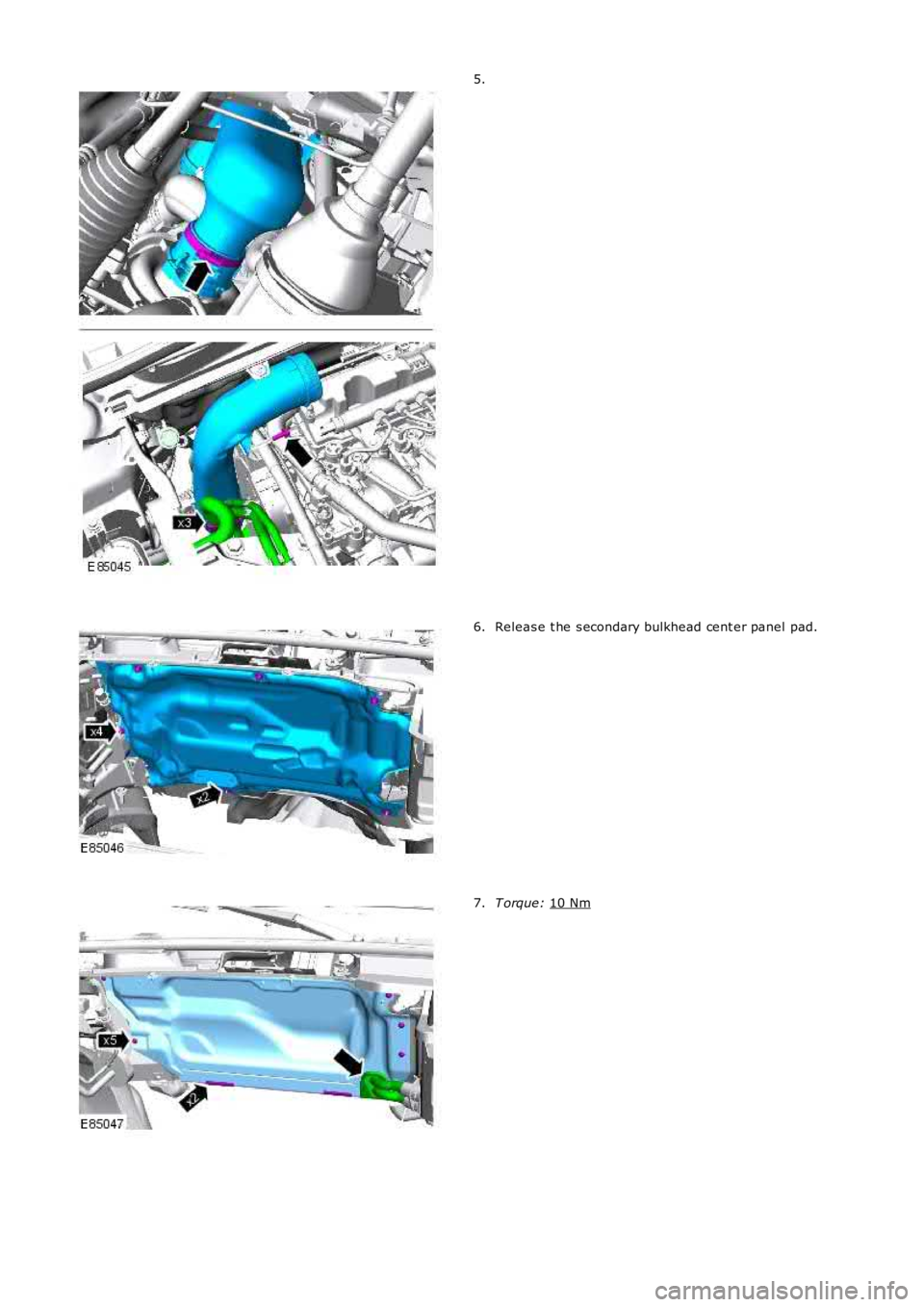
5.
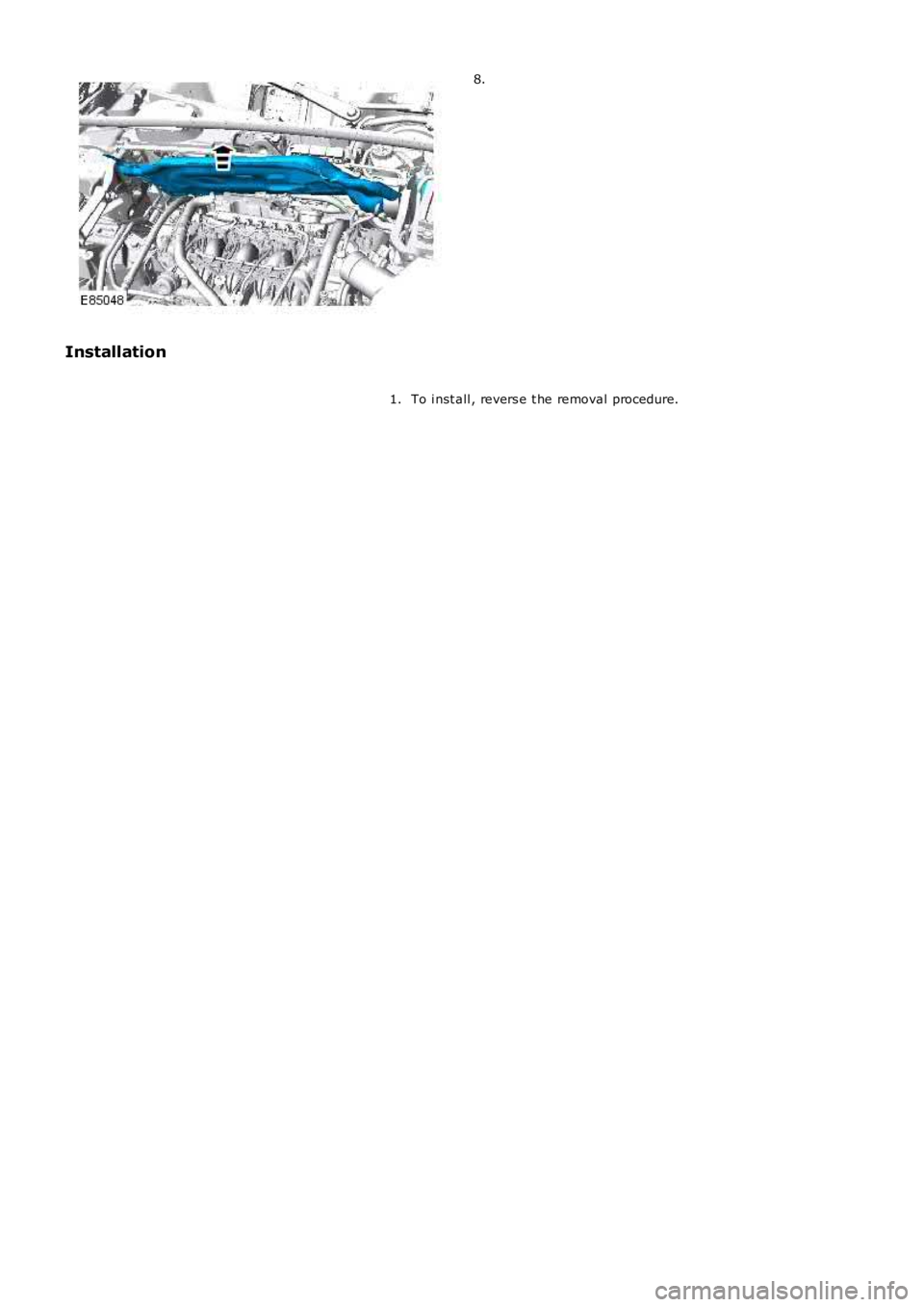
Releas e t he s econdary bulkhead cent er panel pad.
6. T orque:
10 Nm 7.
Page 2092 of 3229
8.
Installation
To i nst all , revers e t he removal procedure.1.
Page 2093 of 3229
Publi s hed: 11-May-2011
Front End Body Panels - Hood Latch Panel
Removal and Inst all ati on
Removal
1. W ARNING: Make sure t o s upport the vehicle wit h axles tands .
Rais e and s upport t he vehi cl e.
1.
Remove t he headl amps .
Refer t o: Headl amp As sembl y (417-01 Ext eri or Li ght ing, Removaland Inst all at ion).
2.
3. NOTE: Do not dis ass embl e further if t he component i s removedfor acces s onl y.
Remove t he front impact sens ors .
Refer t o: Front Impact Severit y Sens or (501-20B Suppl ement alRes traint Sys t em, Removal and Inst all at ion).
3.
Remove t he front fenders .
Refer t o: Fender (501-02 Front End Body Panels , Removal andInst all at ion).
4.
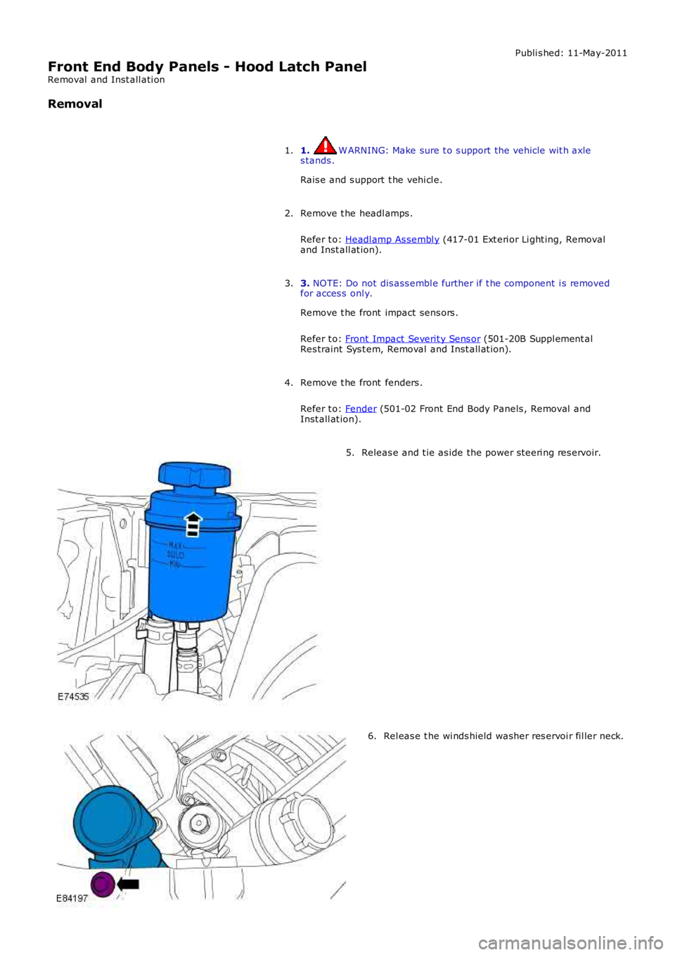
Releas e and t ie as ide the power s teeri ng res ervoir.5.
Rel eas e t he wi nds hield washer res ervoi r fil ler neck.6.
Page 2094 of 3229
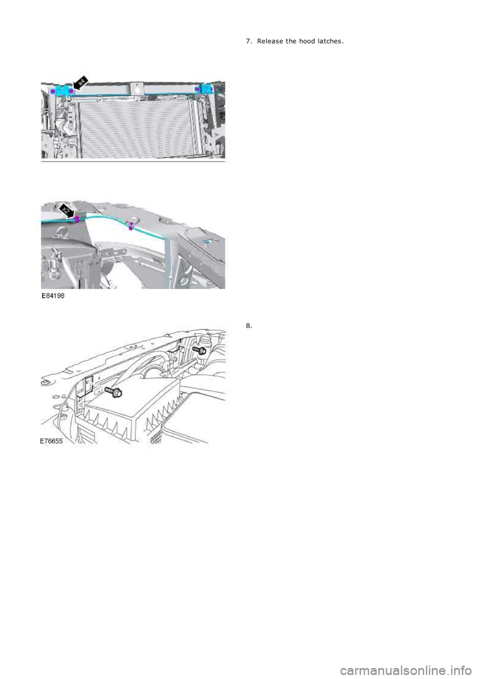
Releas e t he hood latches .7.
8.
Page 2095 of 3229
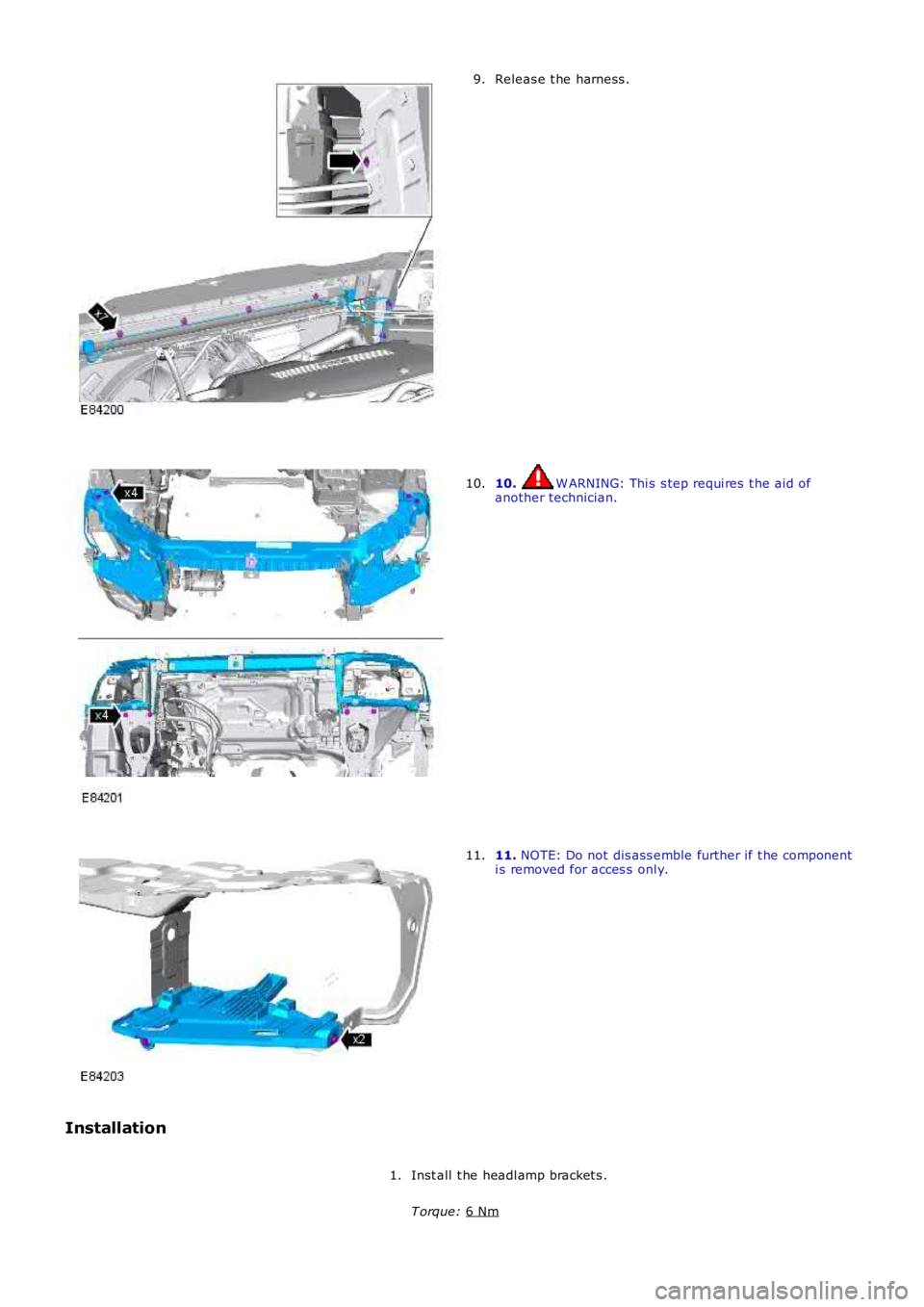
Releas e t he harness .
9. 10. W ARNING: Thi s s tep requi res t he aid of
another technician.
10. 11.
NOTE: Do not dis ass emble further if t he component
i s removed for acces s onl y.
11.
Installation Inst all t he headl amp bracket s .
T orque: 6 Nm 1.
Page 2096 of 3229
2. W ARNING: Thi s s tep requi res t he aid of anot her t echni ci an.
Inst all t he hood latch panel.
T orque: 24 Nm 2.
Secure t he electrical harnes s .
3.
Inst all t he radiat or mount ings .
T orque: 6 Nm 4.
Inst all t he hood latches .
T orque: 10 Nm 5.
Inst all t he winds hield was her res ervoir fil ler neck.
T orque: 6 Nm 6.
Inst all t he power s t eering flui d res ervoir.
7.
Inst all t he front impact sens ors .
Refer t o: Front Impact Severit y Sens or (501-20B Suppl ement al
Res traint Sys t em, Removal and Inst all at ion).
8.
Inst all t he front fenders .
Refer t o: Fender (501-02 Front End Body Panels , Removal and
Inst all at ion).
9.
Inst all t he headl amps .
Refer t o: Headl amp As sembl y (417-01 Ext eri or Li ght ing, Removal
and Inst all at ion).
10.
Page 2097 of 3229
Publi s hed: 11-May-2011
Body Closures -
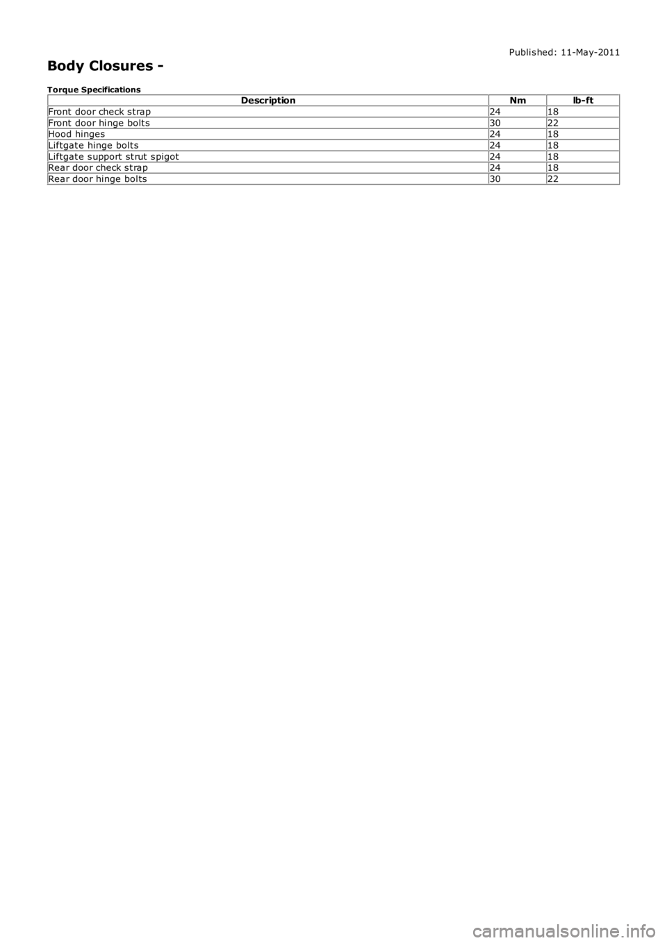
Torque SpecificationsDescriptionNmlb-ft
Front door check s trap2418
Front door hi nge bolt s3022Hood hinges2418
Liftgat e hinge bolt s2418
Liftgat e s upport st rut s pigot2418Rear door check s t rap2418
Rear door hinge bol ts3022
Page 2098 of 3229
Publi s hed: 11-May-2011
Body Closures - Liftgate Alignment
General Procedures
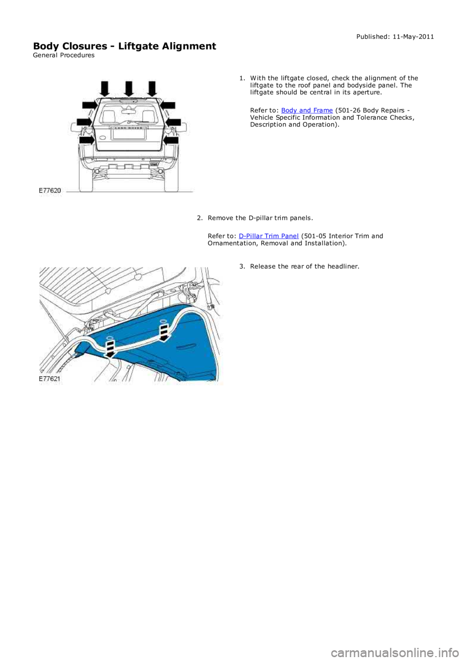
W it h the lift gat e clos ed, check the al ignment of thel ift gate to the roof panel and bodys ide panel. Thel ift gate should be cent ral in it s apert ure.
Refer t o: Body and Frame (501-26 Body Repai rs -Vehicle Specific Informati on and Tol erance Checks ,Des cript ion and Operat ion).
1.
Remove t he D-pi llar t ri m panels .
Refer t o: D-Pi llar Trim Panel (501-05 Int eri or Trim andOrnament ati on, Removal and Ins tal lat ion).
2.
Releas e t he rear of the headli ner.3.
Page 2099 of 3229
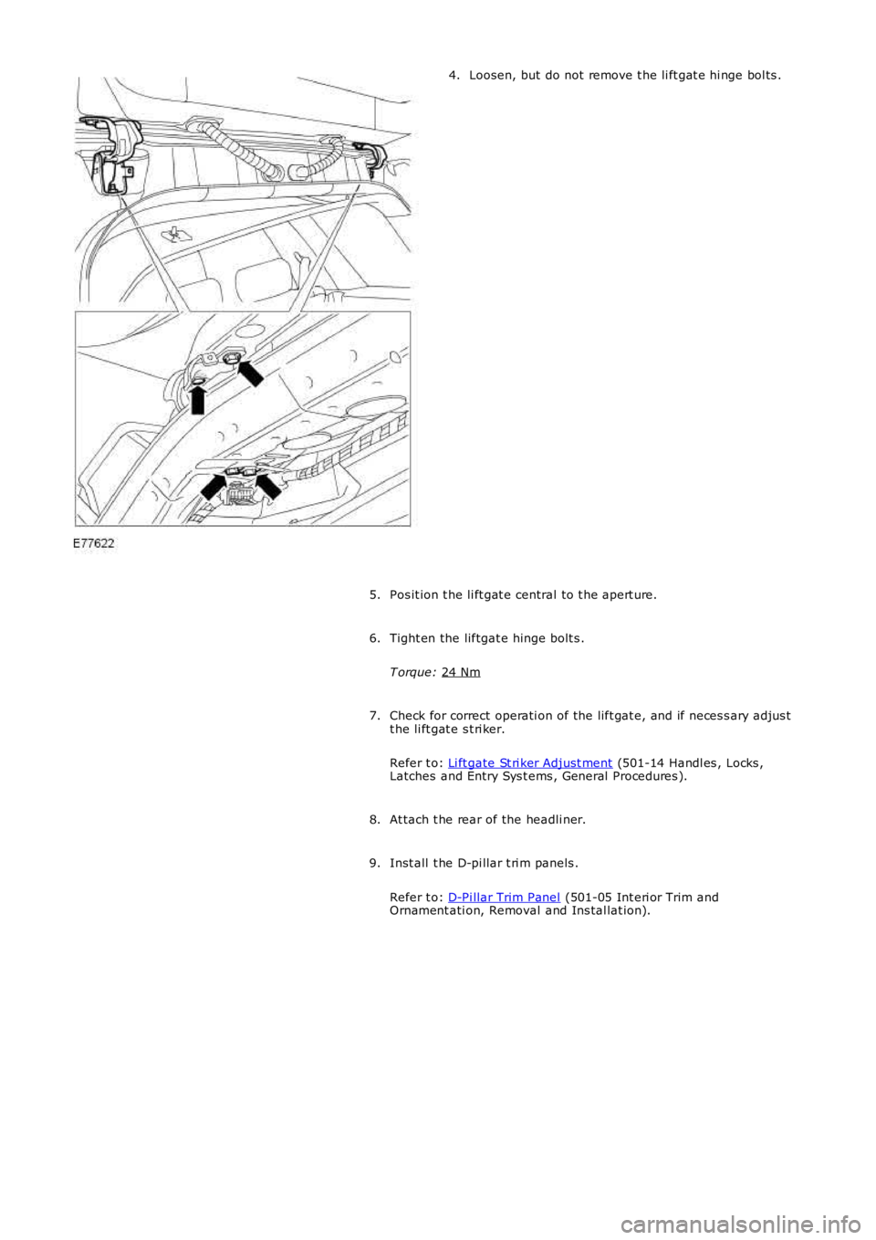
Loosen, but do not remove t he li ft gat e hi nge bol ts .
4.
Pos it ion t he li ft gat e central to t he apert ure.
5.
Tight en the liftgat e hinge bolt s .
T orque: 24 Nm 6.
Check for correct operati on of the lift gat e, and if neces s ary adjus t
t he li ft gat e s t ri ker.
Refer t o: Li ft gate St ri ker Adjust ment (501-14 Handl es , Locks ,
Latches and Entry Sys t ems , General Procedures ).
7.
At tach t he rear of the headli ner.
8.
Inst all t he D-pi llar t ri m panels .
Refer t o: D-Pi llar Trim Panel (501-05 Int eri or Trim and
Ornament ati on, Removal and Ins tal lat ion).
9.
Page 2100 of 3229
Publi s hed: 11-May-2011
Body Closures - Front Door
Removal and Inst all ati on
Removal
1. CAUTION: After s wit chi ng off t he ignit ion, wait for 2 mi nutes
before dis connecti ng the bat tery. Fail ure to wai t for 2 minutes will
damage t he navi gat ion computer.
Di sconnect t he bat t ery ground cable.
Refer t o: Specificati ons (414-00 Bat tery and Charging Sys tem -
General Informat ion, Specificati ons).
1.
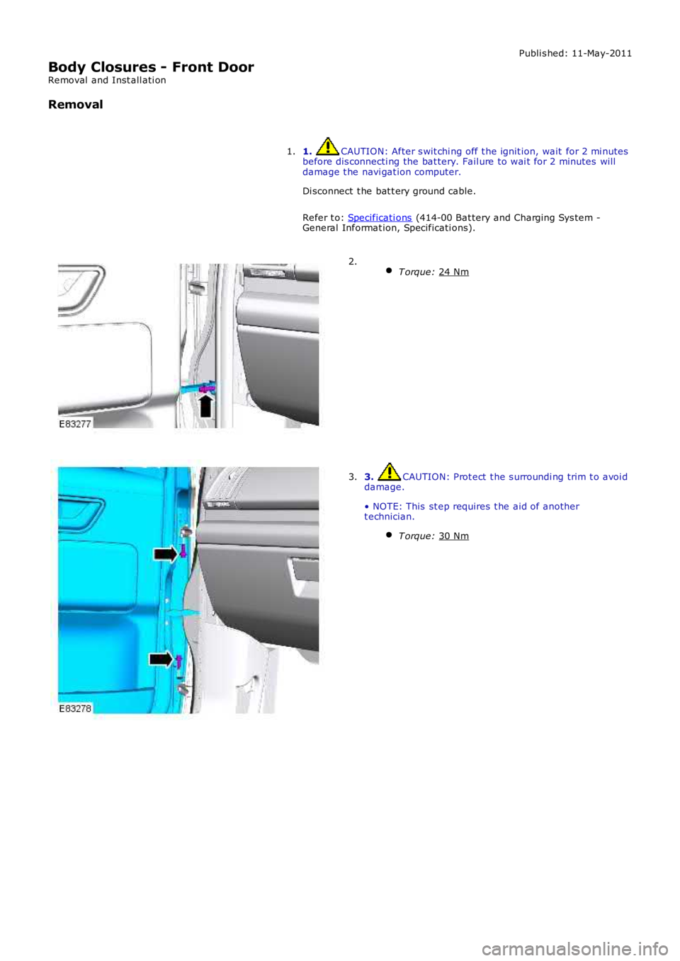
T orque: 24 Nm 2.
3. CAUTION: Prot ect t he s urroundi ng trim t o avoi d
damage.
• NOTE: This st ep requires t he aid of another
t echnician.
T orque: 30 Nm 3.
Trending: glove box, ABS, OBD port, clock, jacking, coolant capacity, set clock
