LAND ROVER FRELANDER 2 2006 Repair Manual
Manufacturer: LAND ROVER, Model Year: 2006, Model line: FRELANDER 2, Model: LAND ROVER FRELANDER 2 2006Pages: 3229, PDF Size: 78.5 MB
Page 531 of 3229
Publi s hed: 11-May-2011
Steering System - General Information - Power Steering System Flushing
General Procedures
• NOTE: If heavy s teering or cont aminat ion wi thi n t he power s t eering s ys tem is found, i t is necess ary to carry out t hes ys t em flus h procedure as det ailed bel ow. If any component s have been replaced in t he power st eeri ng s ys t em t heprocedure below must be carri ed out in full.
• NOTE: Some vari ati on in the i ll us t rat ions may occur, but the es s ent ial informat ion i s always correct .
1. Remove the power s teeri ng fl uid res ervoi r cap.
2. Usi ng a s uit able s yri nge, remove the power s teering fluid fromt he power s t eering flui d res ervoir.
3. CAUTION: Be prepared to col lect escaping fluids .
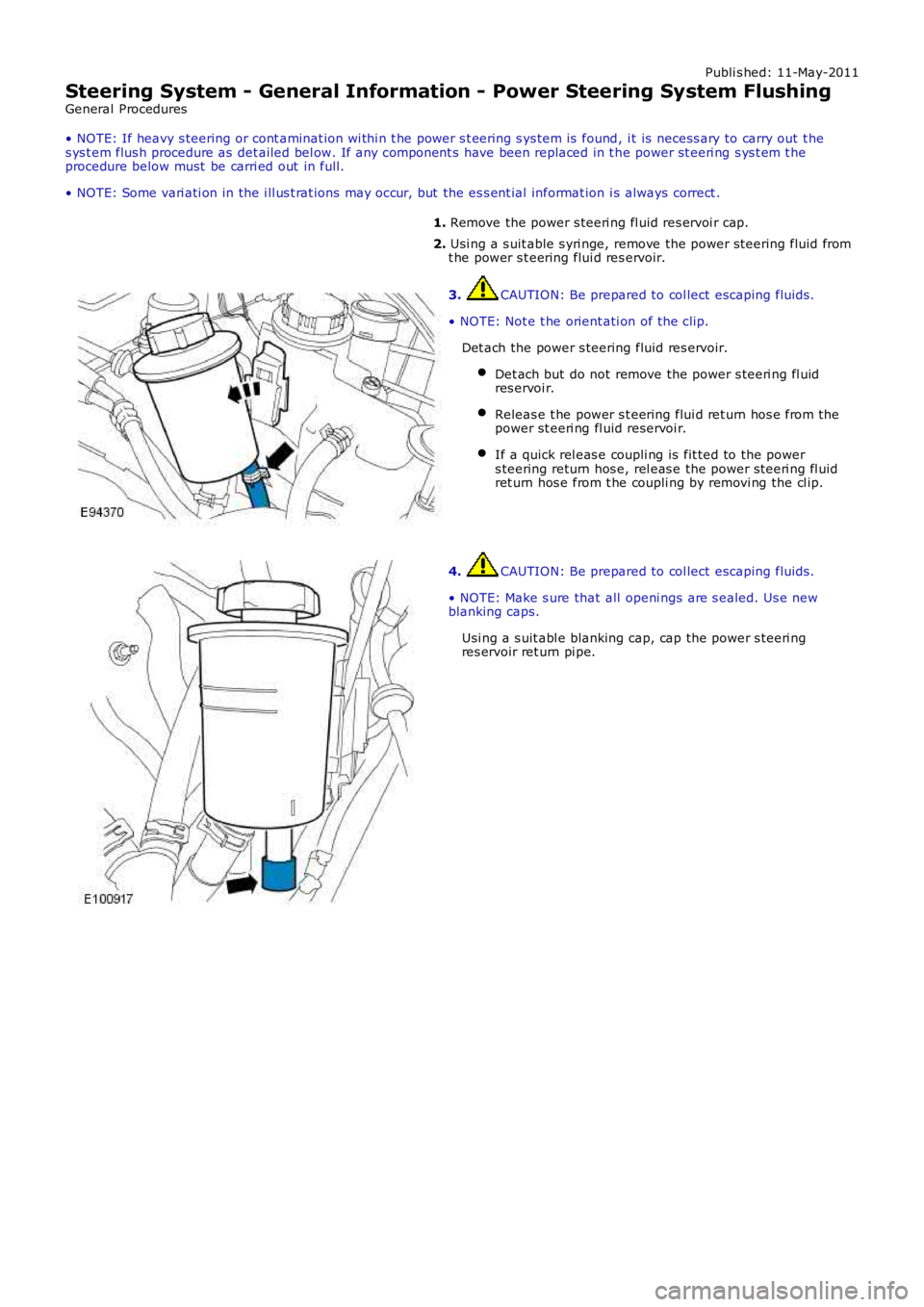
• NOTE: Not e t he orient ati on of the cli p.
Det ach the power s teering fluid res ervoir.
Det ach but do not remove the power s teeri ng fl uidres ervoi r.
Releas e t he power s t eering flui d ret urn hos e from thepower st eeri ng fl uid reservoi r.
If a quick rel eas e coupli ng is fit ted to the powers teering return hos e, rel eas e the power s teeri ng fl uidret urn hos e from t he coupli ng by removi ng the cl ip.
4. CAUTION: Be prepared to col lect escaping fluids .
• NOTE: Make s ure that all openi ngs are s ealed. Us e newblanking caps.
Usi ng a s uit abl e blanking cap, cap the power s teeri ngres ervoir ret urn pi pe.
Page 532 of 3229
5. CAUTION: Be prepared to col lect escaping fluids .
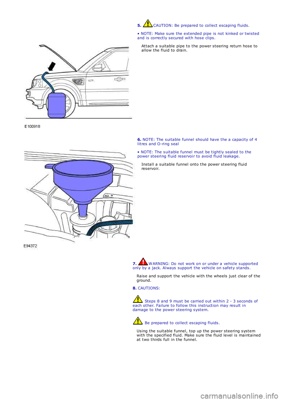
• NOTE: Make s ure the ext ended pipe is not kinked or twi s tedand i s correctl y s ecured wit h hos e clips .
At t ach a s ui table pipe t o t he power s t eering return hos e toal low the flui d to drain.
6. NOTE: The s ui table funnel should have t he a capaci ty of 4l it res and O-ri ng s eal
• NOTE: The s uit abl e funnel mus t be t ightl y s eal ed t o thepower st eeri ng fl uid reservoi r to avoid fl uid l eakage.
Ins tal l a s ui table funnel ont o t he power s t eering flui dres ervoir.
7. W ARNING: Do not work on or under a vehi cl e s upportedonl y by a jack. Al ways support t he vehi cl e on s afet y s tands .
Rais e and s upport t he vehi cl e wi th the wheels jus t cl ear of t heground.
8. CAUTIONS:
Steps 8 and 9 mus t be carried out wit hin 2 - 3 s econds ofeach ot her. Failure t o fol low this ins truct ion may res ult i ndamage to the power s teeri ng s yst em.
Be prepared to col lect es caping fluids .
Us ing the s uit able funnel , top up t he power s teeri ng s ys t emwi th the s peci fi ed fl uid. Make s ure t he fluid level i s mai nt ainedat t wo t hirds full i n t he funnel.
Page 533 of 3229
9. CAUTIONS:
Be prepared t o collect es caping flui ds .
Do not al low the power s teeri ng fl uid l evel i n t he powers teering fluid res ervoir t o fal l bel ow t he mi ni mum powers teering fluid level. Failure t o fol low this ins truct ion may res ulti n damage to the power s teering s yst em.
Make s ure the engine is s wi tched off as s oon as t he ful l4 l it res of power s teeri ng fl uid has ent ered t he power s t eeringfluid res ervoir.
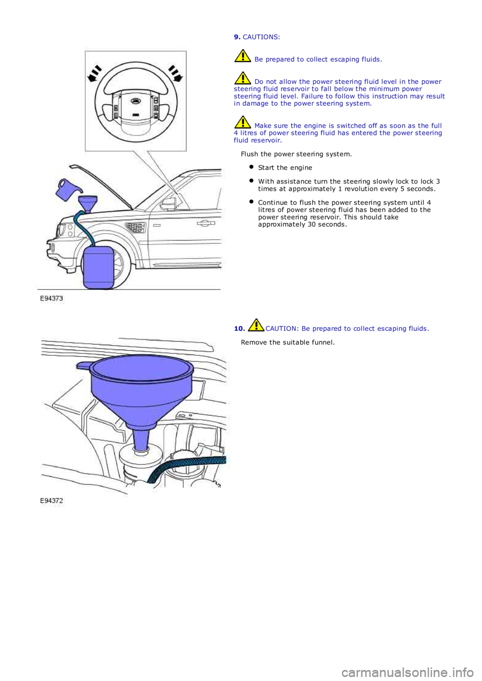
Fl ush the power s teeri ng s yst em.
St art t he engi ne
W it h ass i st ance turn the st eeri ng sl owly l ock to lock 3t imes at approximat ely 1 revolut ion every 5 seconds .
Conti nue to fl us h t he power s teeri ng s ys t em unt il 4l it res of power st eering fl ui d has been added to t hepower st eeri ng res ervoir. Thi s s houl d t akeapproximat ely 30 s econds .
10. CAUTION: Be prepared to col lect es caping fluids .
Remove t he s uit abl e funnel.
Page 534 of 3229
11. CAUTION: Be prepared to col lect es caping fluids .
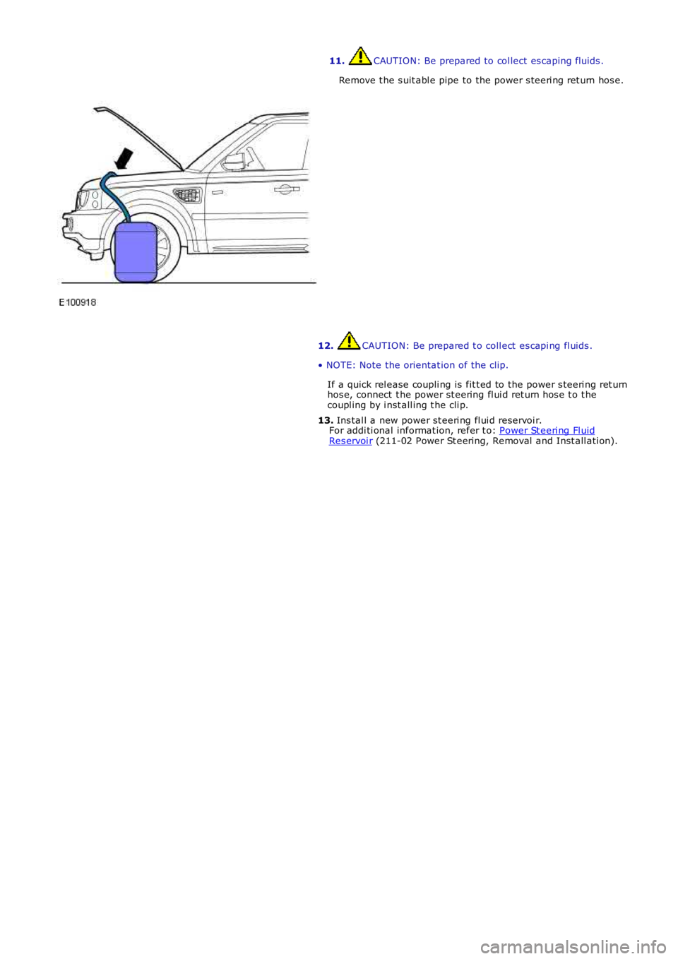
Remove t he s uit abl e pipe to the power s teeri ng ret urn hos e.
12. CAUTION: Be prepared t o coll ect es capi ng fl uids .
• NOTE: Note the orientat ion of t he clip.
If a quick rel ease coupli ng is fit t ed to the power s teeri ng ret urnhos e, connect t he power st eering fl ui d ret urn hos e t o t hecoupl ing by i nst all ing t he cli p.
13. Ins tal l a new power st eeri ng fl ui d reservoi r.For addi ti onal informat ion, refer t o: Power St eeri ng Fl uidRes ervoi r (211-02 Power St eering, Removal and Inst all ati on).
Page 535 of 3229
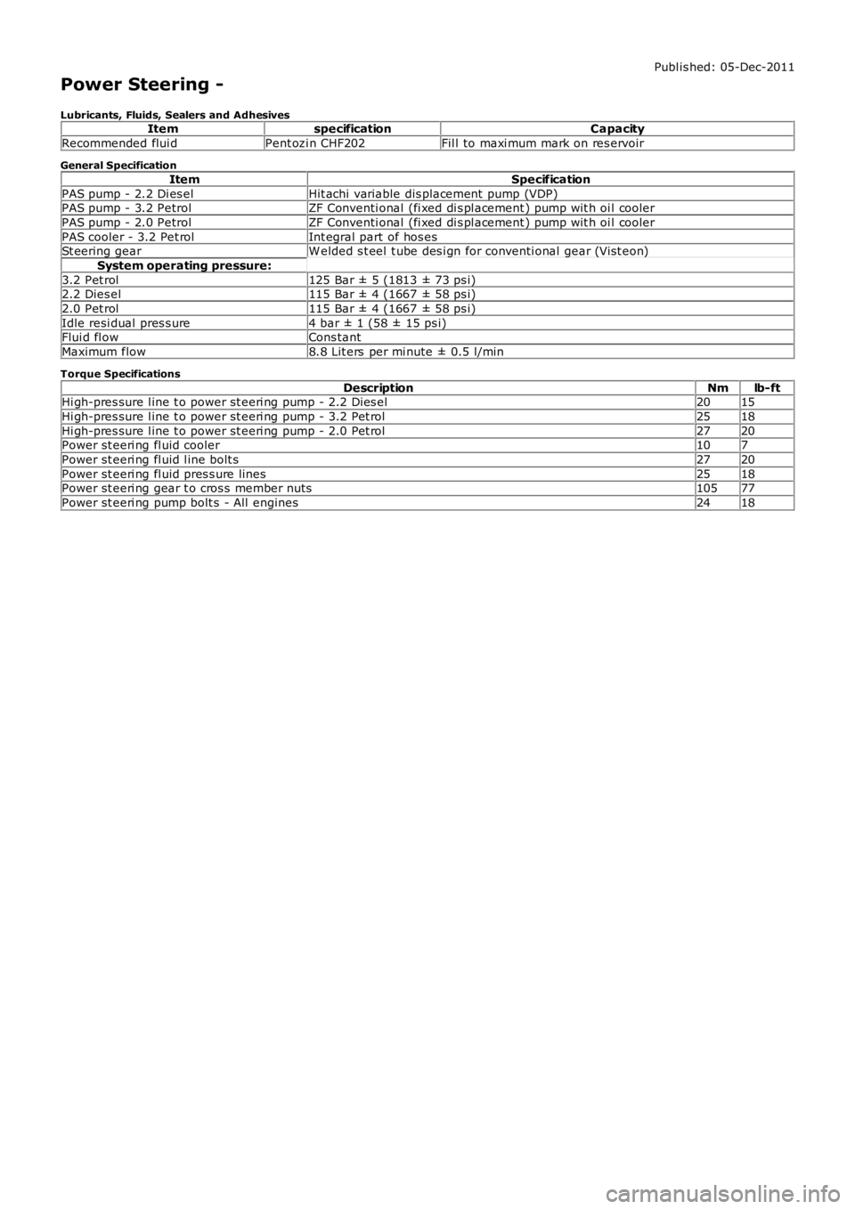
Publ is hed: 05-Dec-2011
Power Steering -
Lubricants, Fluids, Sealers and AdhesivesItemspecificationCapacity
Recommended flui dPent ozi n CHF202Fil l to maxi mum mark on res ervoir
General Specification
ItemSpecification
PAS pump - 2.2 Di es elHit achi variable dis placement pump (VDP)PAS pump - 3.2 PetrolZF Conventi onal (fi xed di s pl acement ) pump wit h oi l cooler
PAS pump - 2.0 PetrolZF Conventi onal (fi xed di s pl acement ) pump wit h oi l cooler
PAS cooler - 3.2 Pet rolInt egral part of hos esSt eering gearW elded s t eel t ube des i gn for conventi onal gear (Vi st eon)
System operating pressure:
3.2 Pet rol125 Bar ± 5 (1813 ± 73 ps i)2.2 Dies el115 Bar ± 4 (1667 ± 58 ps i)
2.0 Pet rol115 Bar ± 4 (1667 ± 58 ps i)
Idle resi dual pres s ure4 bar ± 1 (58 ± 15 ps i)Flui d fl owCons tant
Maximum flow8.8 Lit ers per mi nute ± 0.5 l/min
Torque Specifications
DescriptionNmlb-ftHi gh-pres sure l ine t o power st eeri ng pump - 2.2 Dies el2015
Hi gh-pres sure l ine t o power st eeri ng pump - 3.2 Pet rol2518
Hi gh-pres sure l ine t o power st eeri ng pump - 2.0 Pet rol2720Power st eeri ng fl uid cooler107
Power st eeri ng fl uid l ine bolt s2720
Power st eeri ng fl uid pres s ure lines2518Power st eeri ng gear t o cros s member nuts10577
Power st eeri ng pump bolt s - All engines2418
Page 536 of 3229
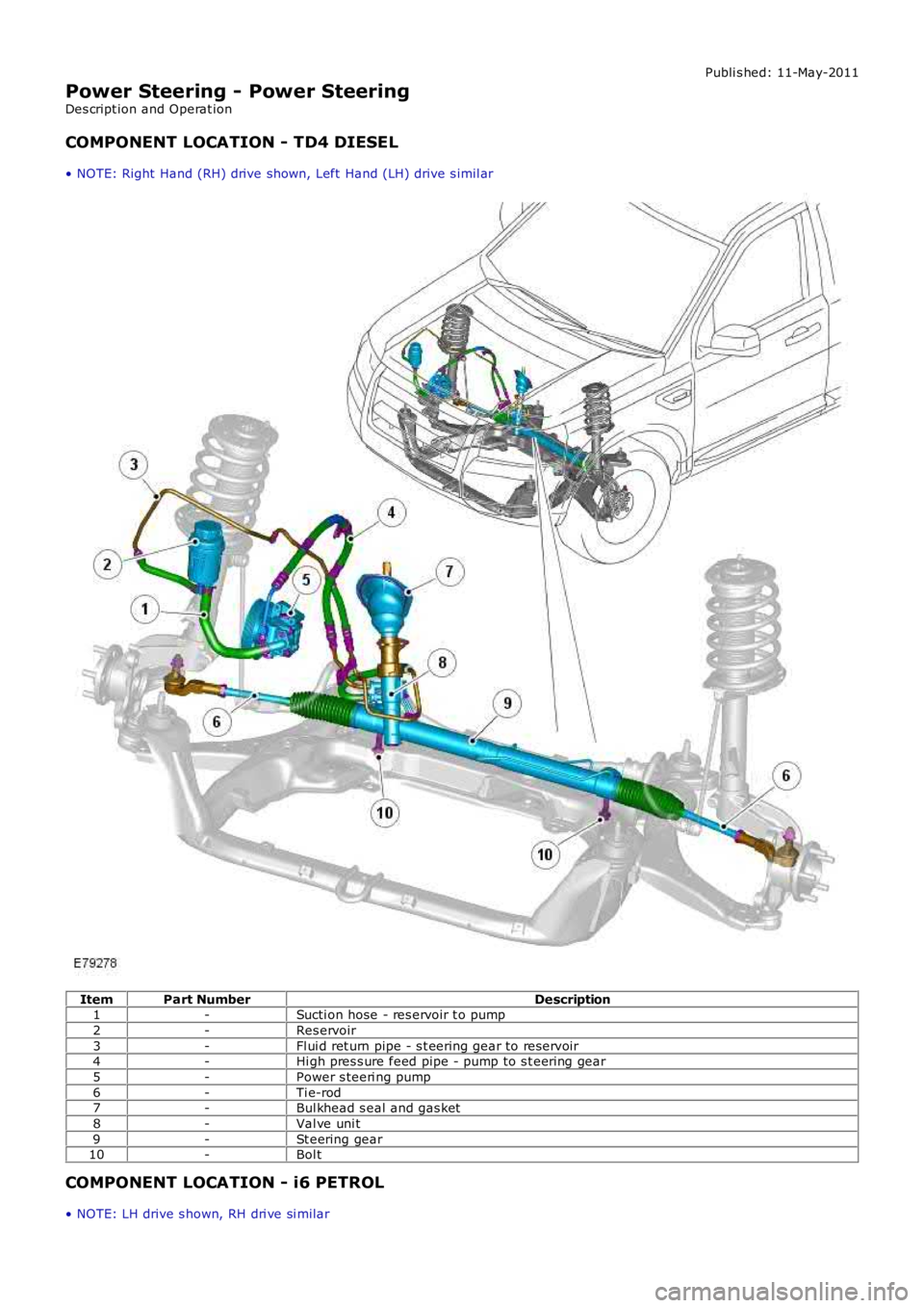
Publi s hed: 11-May-2011
Power Steering - Power Steering
Des cript ion and Operat ion
COMPONENT LOCATION - TD4 DIESEL
• NOTE: Right Hand (RH) drive shown, Left Hand (LH) drive s imil ar
ItemPart NumberDescription1-Sucti on hose - res ervoir t o pump
2-Res ervoir
3-Fl ui d ret urn pipe - s t eering gear to res ervoir4-Hi gh pres s ure feed pipe - pump to s t eering gear
5-Power s teeri ng pump
6-Ti e-rod7-Bul khead s eal and gas ket
8-Val ve uni t
9-St eering gear10-Bol t
COMPONENT LOCATION - i6 PETROL
• NOTE: LH drive s hown, RH dri ve si mi lar
Page 537 of 3229
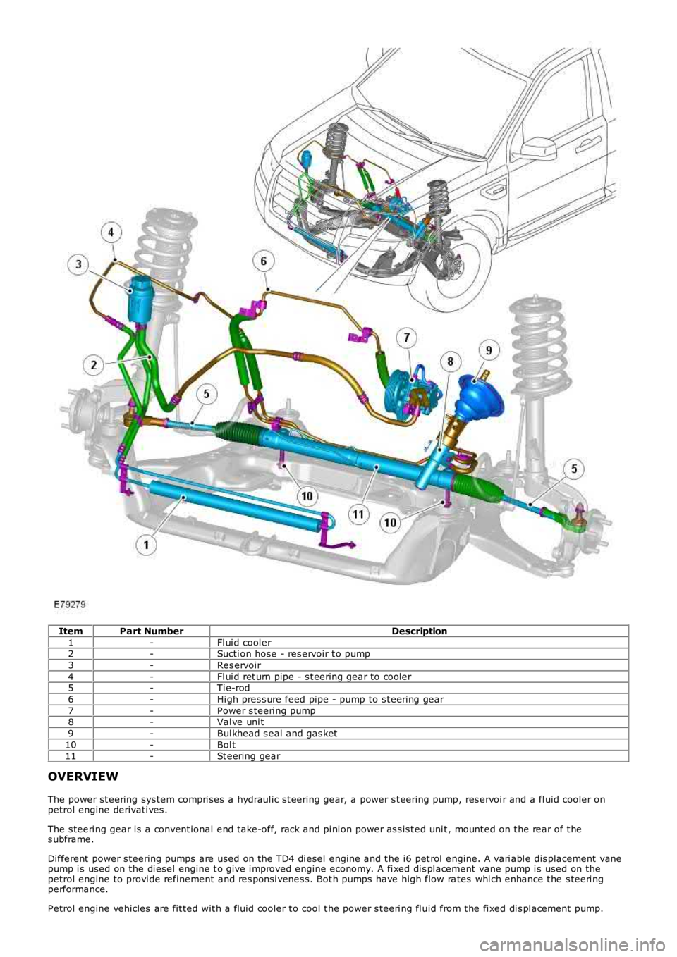
ItemPart NumberDescription
1-Fl ui d cool er2-Sucti on hose - res ervoir t o pump
3-Res ervoir
4-Fl ui d ret urn pipe - s t eering gear to cooler5-Ti e-rod
6-Hi gh pres s ure feed pipe - pump to s t eering gear
7-Power s teeri ng pump8-Val ve uni t
9-Bul khead s eal and gas ket
10-Bol t11-St eering gear
OVERVIEW
The power st eering sys tem compri ses a hydraul ic s t eering gear, a power s t eering pump, res ervoi r and a fl uid cooler onpetrol engine derivati ves .
The s teeri ng gear is a convent ional end take-off, rack and pi ni on power as s is t ed unit , mount ed on t he rear of t hes ubframe.
Different power s teering pumps are used on the TD4 di esel engine and t he i6 pet rol engine. A vari abl e dis placement vanepump i s used on the di esel engine t o give i mproved engine economy. A fi xed di s pl acement vane pump i s used on thepetrol engine to provi de refinement and res pons i venes s. Bot h pumps have high flow rates whi ch enhance t he s teeri ngperformance.
Petrol engine vehicles are fit ted wit h a fluid cooler t o cool t he power s teeri ng fl uid from t he fi xed di s pl acement pump.
Page 538 of 3229
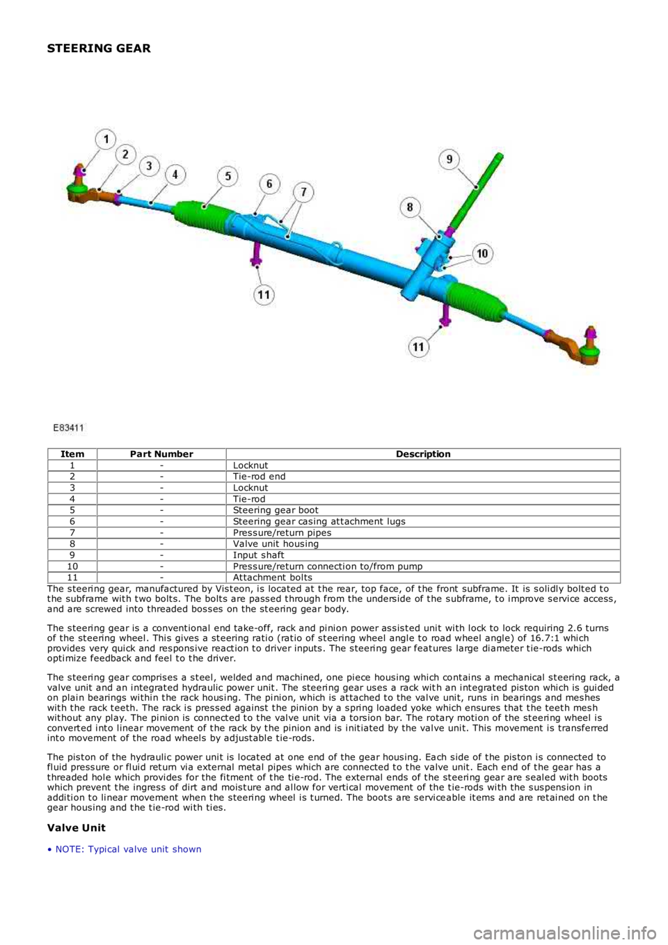
STEERING GEAR
ItemPart NumberDescription
1-Locknut2-Tie-rod end
3-Locknut
4-Tie-rod5-Steering gear boot
6-Steering gear cas ing at t achment lugs
7-Pres s ure/return pipes8-Valve unit hous ing
9-Input s haft
10-Pres s ure/return connecti on to/from pump11-At tachment bol ts
The s teeri ng gear, manufactured by Vis t eon, i s located at t he rear, top face, of t he front subframe. It is s oli dl y bolt ed t ot he subframe wit h t wo bolt s. The bolt s are pass ed t hrough from the unders ide of t he s ubframe, t o i mprove s ervi ce access ,and are screwed into threaded bos s es on the st eering gear body.
The s teeri ng gear is a convent ional end take-off, rack and pi ni on power as s is t ed unit wi th l ock to lock requiring 2.6 turnsof the st eering wheel . Thi s gives a s t eering rati o (rat io of s t eering wheel angl e t o road wheel angl e) of 16.7:1 whi chprovides very qui ck and res pons ive react ion t o driver inputs . The s teeri ng gear features large di ameter t ie-rods whichopti mize feedback and feel t o t he driver.
The s teeri ng gear compris es a s t eel , welded and machined, one pi ece hous ing whi ch cont ai ns a mechanical s t eering rack, avalve unit and an i ntegrat ed hydraulic power unit . The s teeri ng gear us es a rack with an i nt egrat ed pis ton whi ch is gui dedon plai n bearings wi thi n t he rack hous i ng. The pi ni on, whi ch is at tached t o the val ve uni t, runs in bearings and mes heswit h t he rack t eeth. The rack i s pres s ed agai nst t he pini on by a s pri ng loaded yoke which ensures that t he teet h mes hwit hout any pl ay. The pi ni on is connect ed t o t he val ve unit via a tors ion bar. The rotary moti on of the st eeri ng wheel i sconvert ed i nt o l inear movement of t he rack by t he pinion and is i nit iated by the valve uni t. This movement i s transferredint o movement of the road wheel s by adjus t abl e t ie-rods.
The pis t on of the hydrauli c power uni t is l ocat ed at one end of the gear hous ing. Each s ide of t he pis ton i s connected tofl uid press ure or fl ui d ret urn vi a external met al pipes which are connected t o t he valve unit . Each end of t he gear has at hreaded hol e which provi des for the fi tment of t he ti e-rod. The external ends of t he st eeri ng gear are s eal ed wit h bootswhich prevent t he ingres s of dirt and mois t ure and al low for verti cal movement of the t ie-rods wi th the s us pens ion inaddi ti on t o li near movement when t he s teeri ng wheel i s t urned. The boot s are s ervi ceable it ems and are ret ai ned on t hegear hous ing and t he t ie-rod wi th ti es .
Valve Unit
• NOTE: Typi cal valve unit shown
Page 539 of 3229
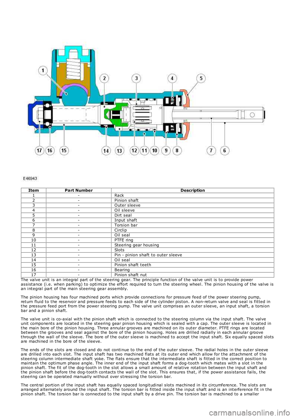
ItemPart NumberDescription
1-Rack
2-Pinion s haft3-Outer s leeve
4-Oil s leeve
5-Dirt s eal6-Input s haft
7-Tors ion bar
8-Circl ip9-Oil s eal
10-PTFE ring
11-Steeri ng gear hous ing12-Slots
13-Pin - pi nion s haft t o outer s leeve
14-Oil s eal15-Pinion s haft t eeth
16-Bearing
17-Pinion s haft nutThe valve unit i s an int egral part of the st eeri ng gear. The principl e functi on of the val ve uni t is t o provi de poweras si st ance (i .e. when parking) t o opti mize the effort required to turn the st eering wheel . The pi nion hous ing of t he val ve isan i nt egral part of t he main st eering gear as sembl y.
The pinion hous ing has four machi ned ports whi ch provide connect ions for pres s ure feed of t he power s t eering pump,ret urn flui d t o t he res ervoir and pres s ure feeds to each s ide of t he cylinder pis t on. A non-ret urn valve and s eal is fit ted int he pres sure feed port from t he power st eeri ng pump. The val ve uni t compris es an outer s l eeve, an input s haft, a torsi onbar and a pinion shaft.
The valve unit i s co-axial wit h t he pinion shaft whi ch is connect ed t o the st eeri ng col umn via the i nput s haft . The val veunit component s are locat ed in the st eering gear pini on hous ing which is sealed wit h a cap. The out er s leeve is l ocat ed int he main bore of the pi nion hous ing. Three annul ar grooves are machined on i ts out er di ameter. PTFE rings are locatedbetween t he grooves and s eal agains t the bore of the pi nion hous ing. Hol es are dril led radiall y in each annular groovet hrough the wal l of the s leeve. The bore of t he out er s leeve is machined t o accept the input s haft . Si x equal ly s paced sl otsare machi ned in t he bore of t he s leeve.
The ends of the s lot s are cl osed and do not conti nue to the end of t he outer s leeve. The radial holes i n the out er sl eeveare dril led i nto each s lot . The input s haft has two machi ned fl at s at i ts out er end whi ch all ow for t he att achment of t hes teeri ng column i ntermedi ate shaft yoke. The fl ats ens ure t hat the intermediate s haft is fit t ed in t he correct pos it ion t omaint ain t he opti mum phas e angle. The inner end of the input shaft forms a dog-t ooth whi ch mates wit h a s lot i n t hepinion shaft. The fit of t he dog-toot h in the s l ot al lows a small amount of relat ive rot ati on between t he input s haft andt he pinion s haft before t he dog-t oot h contacts t he wal l of t he s lot . Thi s ensures that , if t he power as s is tance fai ls , t hes teeri ng can be operated manual ly wi thout over s t res s ing t he tors ion bar.
The cent ral port ion of t he input s haft has equal ly s paced longit udi nal s lot s machined in it s circumference. The s l ot s arearranged al ternat ely around the i nput s haft . The torsi on bar is fit ted ins ide t he input s haft and is an int erference fit i n t hepinion shaft. The t ors ion bar is connect ed t o t he input s haft by a drive pin. The t ors ion bar is machi ned to a s mall er
Page 540 of 3229
diamet er in i ts central sect ion. The smal ler diamet er allows the t ors ion bar t o t wist in res pons e t o t orque appli ed from t hes teeri ng wheel in relati on t o t he grip of the t yres on t he road surface. The pi nion s haft has machined t eet h on it s cent raldiamet er whi ch mat e wit h t eeth on the s t eering gear rack. A s lot , machi ned in t he upper end of t he pini on s haft mateswit h t he dog-t oot h on the i nput s haft . The pinion s haft l ocat es in the pi ni on housi ng and rot ates on bal l and roll erbearings .
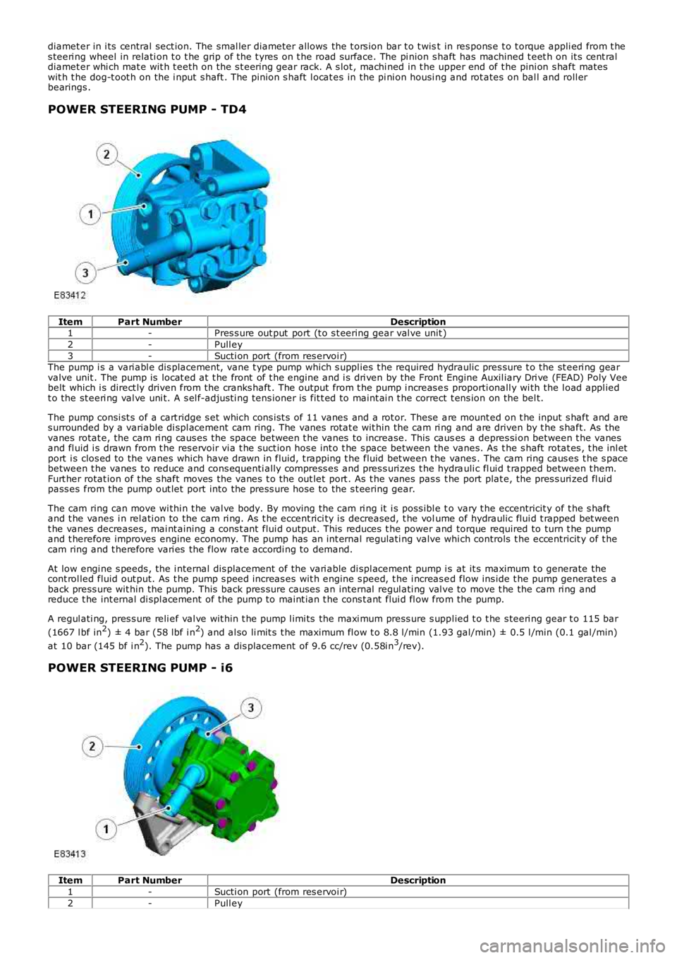
POWER STEERING PUMP - TD4
ItemPart NumberDescription1-Pres s ure out put port (t o s t eering gear val ve unit )
2-Pull ey
3-Sucti on port (from res ervoi r)The pump i s a vari abl e dis placement, vane t ype pump which s uppl ies t he required hydraulic pres sure t o the st eeri ng gearvalve unit . The pump is locat ed at t he front of t he engine and i s dri ven by the Front Engine Auxil iary Dri ve (FEAD) Poly Veebelt which i s direct ly driven from the cranks haft . The out put from t he pump i ncreas es proporti onall y wi th the l oad appl iedt o the st eeri ng val ve uni t. A s el f-adjus ti ng tens ioner is fit t ed to maint ai n t he correct t ens ion on the bel t.
The pump consi st s of a cart ridge s et which cons is t s of 11 vanes and a rot or. These are mount ed on t he input s haft and ares urrounded by a variable di spl acement cam ring. The vanes rotat e wit hin the cam ri ng and are driven by t he s haft. As thevanes rotat e, the cam ri ng caus es the space between t he vanes to increase. This causes a depres si on between t he vanesand fl uid i s drawn from t he res ervoir vi a t he suct ion hos e int o t he s pace between the vanes. As t he s haft rotat es , t he inl etport i s clos ed to the vanes which have drawn in fluid, t rapping t he fluid bet ween t he vanes . The cam ring caus es t he s pacebetween t he vanes to reduce and cons equenti ally compress es and pres s uri zes t he hydrauli c fl ui d t rapped between t hem.Furt her rotat ion of t he s haft moves the vanes t o the out let port . As t he vanes pas s t he port plat e, the pres s uri zed fl ui dpass es from the pump out let port into the press ure hose to the s t eering gear.
The cam ring can move wi thi n t he val ve body. By moving the cam ri ng it i s poss ibl e to vary t he eccentricit y of t he s haftand t he vanes i n rel ati on to the cam ri ng. As t he eccent rici ty i s decreased, t he volume of hydraulic flui d t rapped bet weent he vanes decreases , mai nt aining a cons t ant flui d output. This reduces t he power and torque required to turn t he pumpand t herefore improves engine economy. The pump has an int ernal regulati ng valve which controls t he eccentricit y of t hecam ring and t herefore vari es the flow rat e accordi ng to demand.
At low engi ne s peeds , the i nternal dis placement of the vari able di spl acement pump i s at it s maximum t o generate thecont rol led fluid out put. As t he pump s peed increas es wit h engine s peed, t he i ncreas ed flow ins ide t he pump generates aback press ure wit hin the pump. This back pres s ure causes an internal regul ati ng val ve to move t he the cam ri ng andreduce t he int ernal di spl acement of the pump to maint ian t he cons t ant flui d fl ow from the pump.
A regul ati ng, pres s ure reli ef val ve wit hin t he pump l imi ts the maxi mum press ure s uppl ied t o t he s teeri ng gear t o 115 bar
(1667 l bf in2) ± 4 bar (58 lbf i n2) and al so li mit s t he maximum fl ow t o 8.8 l/min (1.93 gal/min) ± 0.5 l /min (0.1 gal /min)
at 10 bar (145 bf i n2). The pump has a dis placement of 9.6 cc/rev (0.58i n3/rev).
POWER STEERING PUMP - i6
ItemPart NumberDescription
1-Sucti on port (from res ervoi r)
2-Pull ey