LAND ROVER FRELANDER 2 2006 Repair Manual
Manufacturer: LAND ROVER, Model Year: 2006, Model line: FRELANDER 2, Model: LAND ROVER FRELANDER 2 2006Pages: 3229, PDF Size: 78.5 MB
Page 541 of 3229
3-Pres s ure out put port (t o s t eering gear val ve unit )
The pump i s a fixed dis placement, vane type pump which s uppl ies hydrauli c pres sure to t he st eeri ng gear valve unit . Thepump i s located at t he rear of t he engi ne and is driven by t he Rear Engi ne Auxi liary Drive (READ) Poly Vee bel t which i sindirect ly driven from t he cams haft s . The pump s uppl ies a cons tant fl ow rate, t herefore the out put i s i ndependent ofpump/engine s peed. A s el f-adjus ti ng tens ioner is fit t ed to maint ai n t he correct t ension on the bel t.
The pump contains a number of vanes which rot ate wit hin a cam ri ng and are driven by t he i nput s haft . As the vanesrot ate, t he cam ring causes t he s pace bet ween the vanes t o increas e. Thi s caus es a depres s ion bet ween the vanes andfl uid i s drawn from t he res ervoir vi a t he suct ion hos e int o t he s pace between the vanes. As t he s haft rotat es , t he inl etport i s clos ed to the vanes which have drawn in fluid, t rapping t he fluid bet ween t he vanes . The cam ring caus es t he s pacebetween t he vanes to reduce and cons equenti ally compress es and pres s uri zes t he hydrauli c fl ui d t rapped between t hem.Furt her rotat ion of t he s haft moves the vanes t o the out let port . As t he vanes pas s t he port plat e t he pres surized fluidpass es from the pump out let port into the press ure hose to the s t eering gear.
The pres s urized fluid is s ubject t o cont rol by a flow cont rol and pres s ure relief valve. The fl ow control valve maintai ns acons t ant flow of flui d s uppl ied t o t he s teeri ng gear irres pecti ve of engi ne s peed variati ons . The pres s ure reli ef val ve limit st he maximum pres sure on t he output s ide of t he pump. A met eri ng orifice i s included i n t he dis charge port of the pump.
If the pres s ure in t he ori fi ce reaches a predetermined l evel , a s pring loaded bal l in t he cent re of the flow cont rol valve isli ft ed from it s s eat and al lows pres s uri zed flui d t o recircul ate wit hi n t he pump. The pres sure rel ief valve wi ll operate if t hedis charge from the pump is rest ri ct ed, for example, s teeri ng held on full l ock. If the output from the pump is bl ocked, al loutput is recirculat ed t hrough the pump. In t his condi ti on, as no fresh fl ui d i s drawn i nto the pump from t he res ervoir, thefl uid t emperat ure i nsi de t he pump wil l increas e rapi dl y. Cons equent iall y, periods of operati on of the s t eering gear on ful llock s houl d be kept to a mi nimum to prevent overheati ng of the pump and the flui d within it .
The pump has an i nternal pres s ure reli ef valve whi ch als o i ncorporat es a flow cont rol val ve. The press ure rel ief val ve li mit s
t he maximum pres sure s uppl ied t o t he s teering gear to 125 bar (1812 lbf in2) ± 4 bar (58 l bf in2). The flow control val ve
li mit s t he maximum flow t o 8.8 l/mi n (1.93 gal/min) ± 0.5 l/min (0.1 gal/min) at 10 bar (145 bf i n2) The pump has a
dis placement of 11 cc/rev (0.67 i n3/rev).
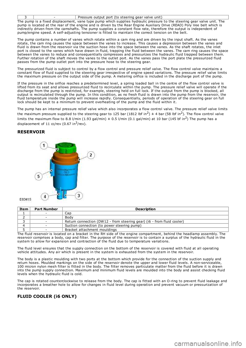
RESERVOIR
ItemPart NumberDescription1-Cap
2-Body
3-Ret urn connect ion (DW 12 - from s teering gear) (i6 - from fluid cool er)4-Sucti on connecti on (t o power s teeri ng pump)
5-Bracket att achment moul dings
The fl uid res ervoi r is locat ed on a bracket in the RH s ide of t he engi ne compartment, behi nd t he headl amp as sembl y. Theres ervoir compri s es a body, cap and filt er. The purpos e of t he res ervoir i s t o cont ain a surplus of t he hydraul ic fluid in thes ys t em t o al low for expans ion and cont ract ion of t he fl uid due t o t emperature vari ations .
The fl uid l evel ens ures t hat t he s uppl y connecti on on t he bot t om of t he res ervoir i s covered wit h fluid at al l operat ingvehi cl e at ti tudes. Any ai r which is pres ent i n t he s ys t em i s exhaus ted from t he s ys tem i n t he res ervoir.
The body is a plas ti c moulding wit h two port s at the bot tom which provi de for t he connecti on of the s ucti on supply andret urn hos es . Moul ded markings on the s ide of t he reservoi r denot e the upper and lower fluid level s . A non-s erviceable,100 mi cron nylon mes h fil ter is fi tt ed in the body. The fi lt er removes parti cul ate matt er from t he fl uid before i t is drawnint o t he pump s uppl y connecti on. Maximum and minimum fluid level s are moulded int o the body and ass is t checking fl ui dlevels when the hydrauli c fl uid i s cold.
The cap is rotat ed count erclockwi s e t o rel eas e from t he body. The cap is fit t ed wit h an O-ri ng t o prevent fl ui d l eakage andincorporat es a breat her hol e to allow for changes i n fluid level duri ng operati on and prevent vacuum or pres s uri zat ion oft he res ervoir.
FLUID COOLER (i6 ONLY)
Page 542 of 3229
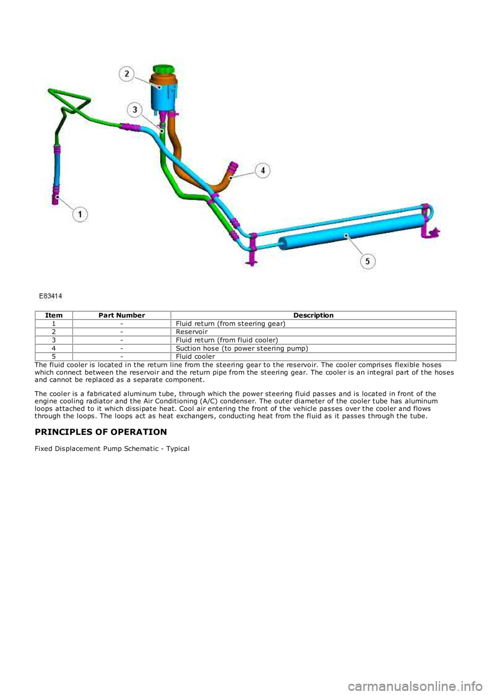
ItemPart NumberDescription
1-Fluid ret urn (from s t eering gear)2-Reservoi r
3-Fluid ret urn (from flui d cool er)
4-Suct ion hos e (to power s t eering pump)5-Fluid cooler
The fl uid cooler is locat ed i n t he ret urn l ine from the st eeri ng gear t o t he res ervoir. The cool er compri s es fl exi bl e hos eswhich connect between t he res ervoi r and the return pipe from the st eeri ng gear. The cooler i s an i nt egral part of t he hos esand cannot be repl aced as a s eparat e component .
The cool er is a fabri cat ed alumi num t ube, t hrough which t he power st eering fl ui d passes and i s located in front of theengi ne cool ing radiator and t he Air Condit ioning (A/C) condens er. The out er di ameter of the cooler t ube has aluminumloops at tached to it which di ss i pat e heat. Cool air entering t he front of t he vehicle pas s es over t he cool er and flowst hrough the l oops . The l oops act as heat exchangers , conducti ng heat from t he fl uid as it pass es t hrough t he tube.
PRINCIPLES OF OPERATION
Fixed Dis placement Pump Schemat ic - Typical
Page 543 of 3229
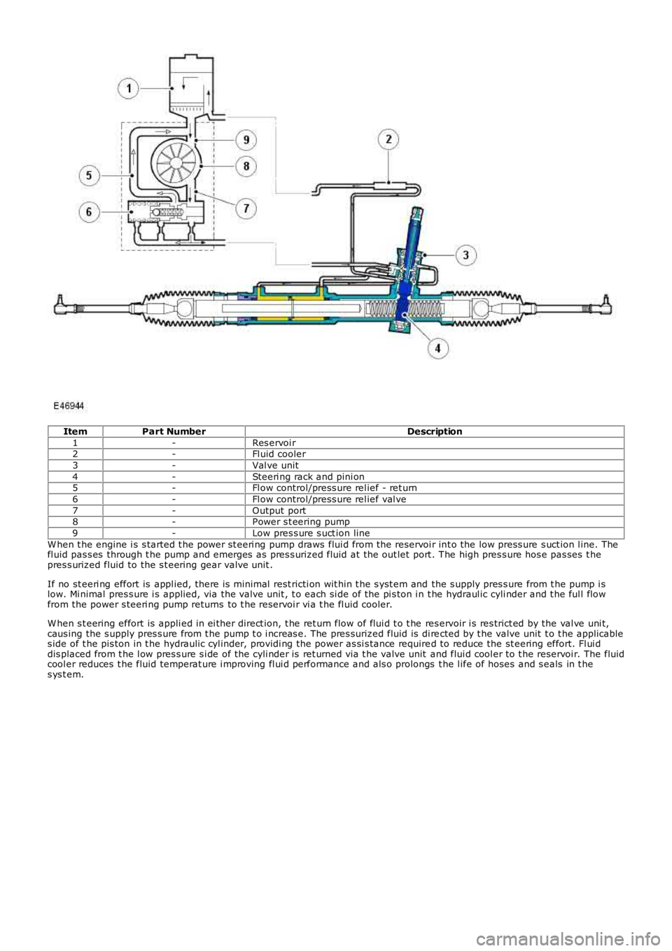
ItemPart NumberDescription
1-Res ervoi r2-Fl uid cooler
3-Val ve unit
4-Steeri ng rack and pini on5-Fl ow control/press ure rel ief - ret urn
6-Fl ow control/press ure rel ief val ve
7-Output port8-Power s t eering pump
9-Low pres s ure s uct ion line
W hen t he engine i s s tarted t he power st eeri ng pump draws flui d from the reservoi r int o the low press ure s uct ion l ine. Thefl uid pas s es through t he pump and emerges as pres s urized fluid at the out let port . The high pres s ure hos e pas ses t hepres s urized fluid to the s t eering gear valve unit .
If no st eeri ng effort is appl ied, there is minimal rest ricti on wit hin t he s yst em and the s upply pres s ure from t he pump i slow. Mi nimal pres s ure i s applied, via the valve unit , t o each si de of the pi s ton i n t he hydraul ic cyli nder and t he ful l flowfrom the power s teeri ng pump returns to t he reservoi r vi a t he fl uid cooler.
W hen s t eering effort is appli ed in ei ther direct ion, t he ret urn flow of flui d t o t he res ervoir i s res trict ed by the val ve uni t,caus ing the s upply pres s ure from t he pump t o i ncreas e. The pres surized fluid is di rected by t he valve unit t o t he applicables ide of t he pis ton in t he hydrauli c cyl inder, providi ng the power as si s tance required to reduce the st eering effort. Fl ui ddis placed from t he l ow pres s ure s i de of the cyli nder is ret urned via t he valve unit and flui d cool er to t he reservoi r. The fluidcool er reduces t he fluid temperat ure i mproving fl ui d performance and als o prolongs the l ife of hoses and s eals in t hes ys t em.
Page 544 of 3229
Publi s hed: 11-May-2011
Power Steering - Power Steering
Diagnosi s and Tes ti ng
For addit ional informat ion.REFER to: St eering Sys tem (211-00 Steeri ng Sys t em - General Informati on, Di agnos is and Tes ti ng).
Page 545 of 3229
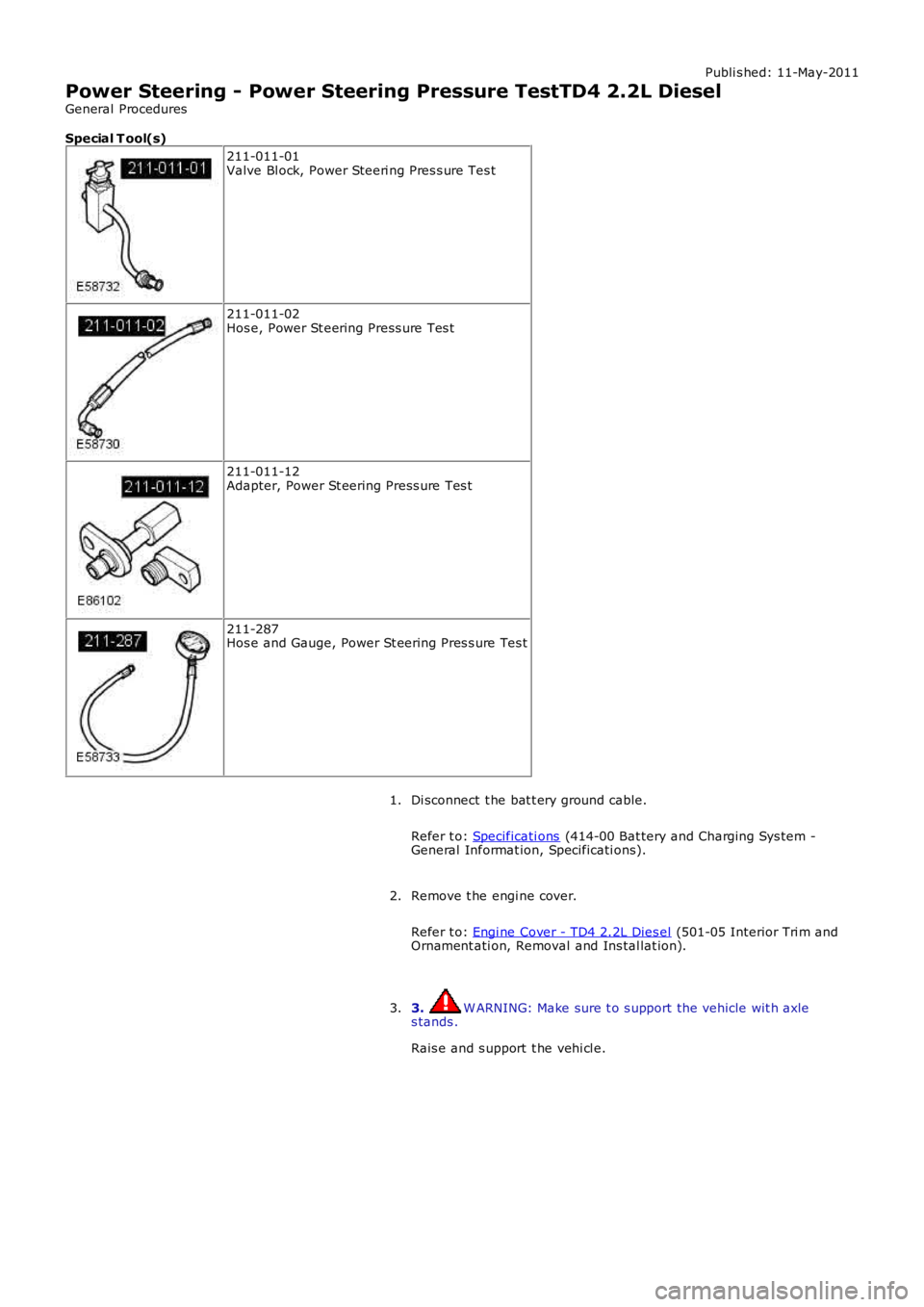
Publi s hed: 11-May-2011
Power Steering - Power Steering Pressure TestTD4 2.2L Diesel
General Procedures
Special T ool(s)
211-011-01Valve Bl ock, Power Steeri ng Pres s ure Tes t
211-011-02Hos e, Power St eering Press ure Tes t
211-011-12Adapter, Power St eering Press ure Tes t
211-287Hos e and Gauge, Power St eering Pres s ure Tes t
Di sconnect t he bat t ery ground cable.
Refer t o: Specificati ons (414-00 Bat tery and Charging Sys tem -General Informat ion, Specificati ons).
1.
Remove t he engi ne cover.
Refer t o: Engi ne Cover - TD4 2.2L Dies el (501-05 Interior Tri m andOrnament ati on, Removal and Ins tal lat ion).
2.
3. W ARNING: Make sure t o s upport the vehicle wit h axles tands .
Rais e and s upport t he vehi cl e.
3.
Page 546 of 3229
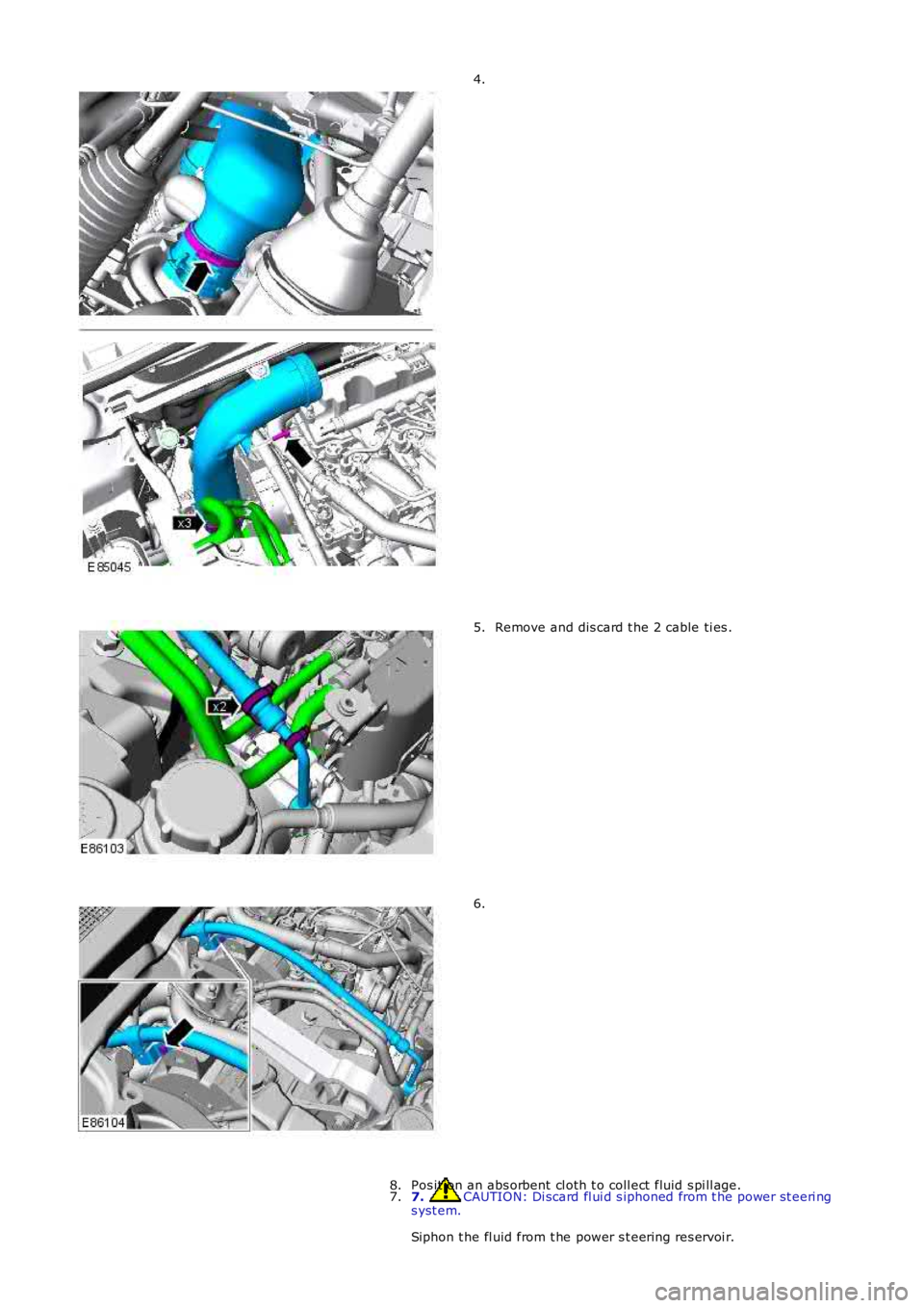
4.
Remove and dis card t he 2 cable ti es .5.
6.
7. CAUTION: Di scard fl ui d s iphoned from t he power st eeri ngs yst em.
Siphon t he fl uid from t he power s t eering res ervoi r.
7.Pos it ion an abs orbent cl oth t o coll ect fluid s pi ll age.8.
Page 547 of 3229
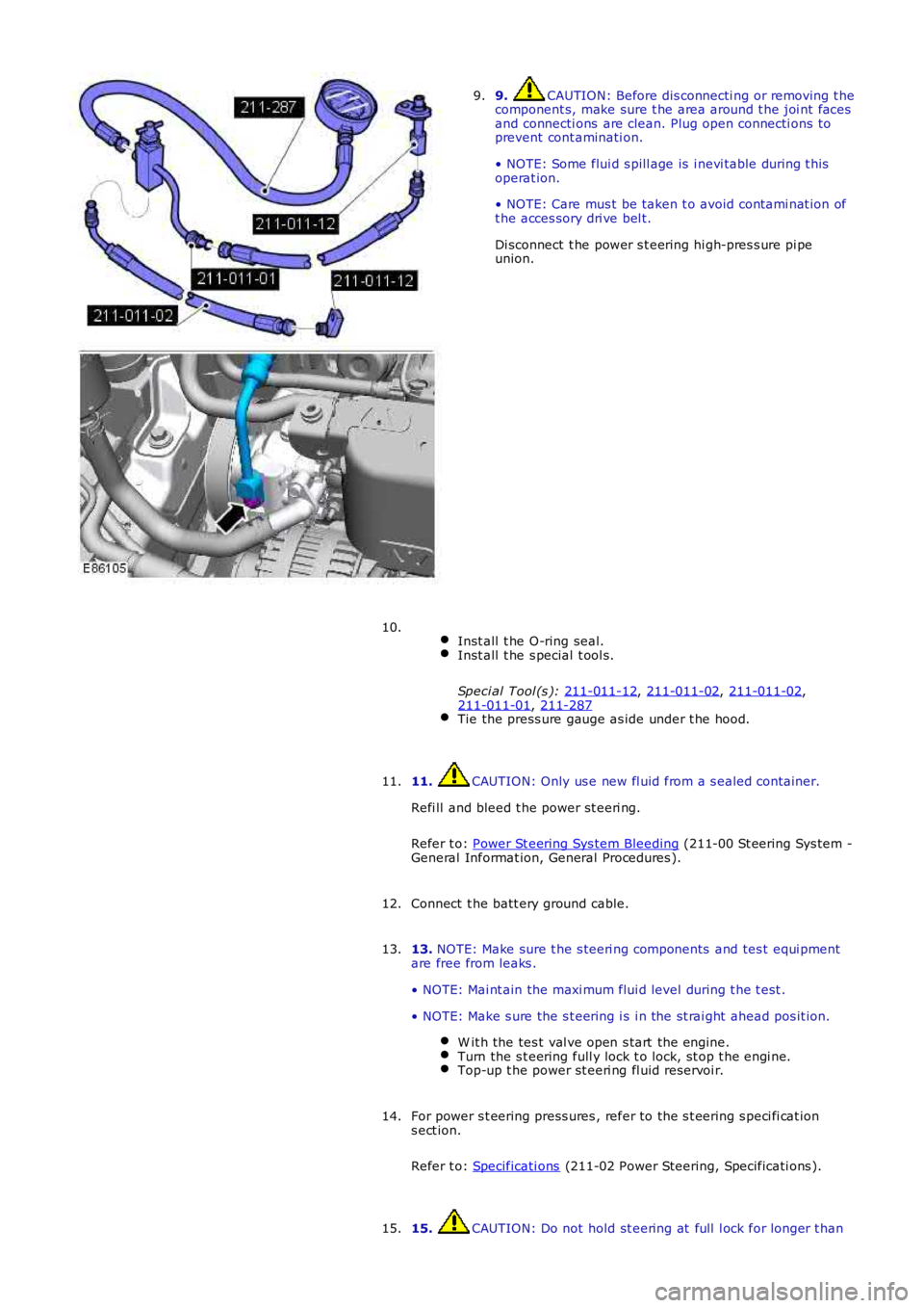
9. CAUTION: Before dis connecti ng or removing t he
component s, make sure t he area around t he joi nt faces
and connecti ons are clean. Plug open connecti ons to
prevent cont aminati on.
• NOTE: Some flui d s pill age is i nevi table during t his
operat ion.
• NOTE: Care mus t be taken t o avoid contami nat ion of
t he acces sory dri ve bel t.
Di sconnect t he power s t eering hi gh-pres s ure pi pe
union.
9.
Inst all t he O-ring seal. Inst all t he s pecial t ool s.
Speci al Tool (s ): 211-011-12 ,
211-011-02 ,
211-011-02 ,
211-011-01 ,
211-287 Tie the press ure gauge as ide under t he hood.10.
11. CAUTION: Only us e new fl uid from a s ealed container.
Refi ll and bleed t he power st eeri ng.
Refer t o: Power St eering Sys tem Bleeding (211-00 St eering Sys tem -
General Informat ion, General Procedures ).
11.
Connect t he batt ery ground cable.
12.
13. NOTE: Make sure t he s teeri ng components and tes t equi pment
are free from leaks .
• NOTE: Mai nt ain the maxi mum flui d level during t he t est .
• NOTE: Make s ure the s t eering i s i n the st rai ght ahead pos it ion. W it h the tes t val ve open s tart the engine. Turn the s t eering full y lock t o lock, st op t he engi ne.
Top-up t he power st eeri ng fl uid reservoi r.13.
For power s t eering press ures , refer to the s t eering s peci fi cat ion
s ect ion.
Refer t o: Specificati ons (211-02 Power Steering, Specificati ons ).
14.
15. CAUTION: Do not hold st eering at full l ock for longer t han
15.
Page 548 of 3229
10 s econds .
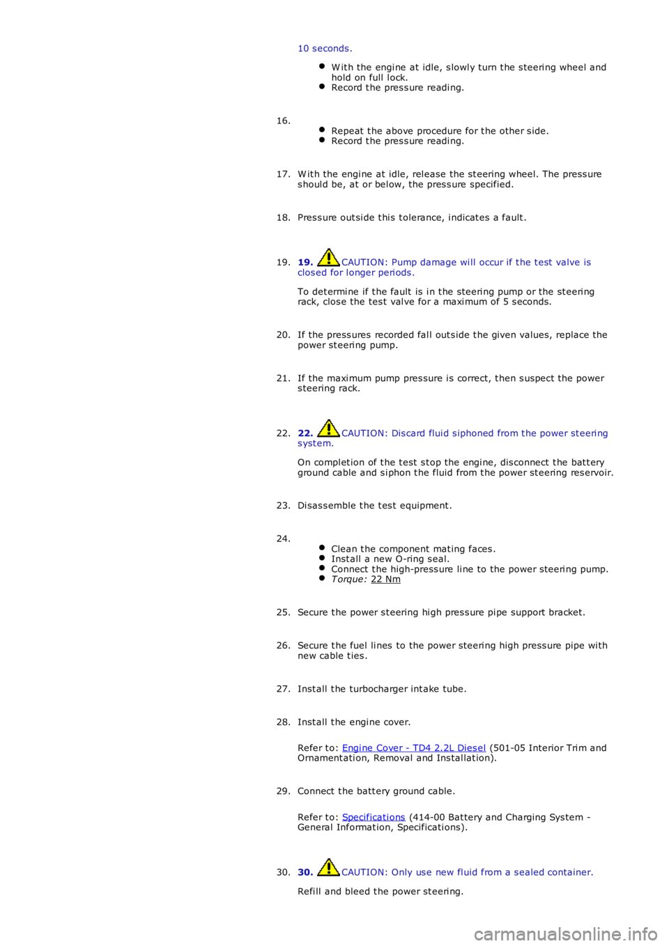
W it h the engi ne at idle, s lowl y turn t he s teeri ng wheel and
hold on full l ock. Record t he pres s ure readi ng.
Repeat t he above procedure for t he other s ide. Record t he pres s ure readi ng.16.
W it h the engi ne at idle, rel ease the s t eering wheel. The press ure
s houl d be, at or bel ow, the pres s ure specified.
17.
Pres s ure out si de t hi s t olerance, i ndicat es a fault .
18.
19. CAUTION: Pump damage wi ll occur if t he t est valve is
clos ed for l onger peri ods .
To det ermi ne if t he fault is i n t he st eeri ng pump or the st eeri ng
rack, clos e the tes t val ve for a maxi mum of 5 s econds.
19.
If the press ures recorded fal l out s ide t he given values, replace the
power st eeri ng pump.
20.
If the maxi mum pump pres sure i s correct, t hen s uspect the power
s teering rack.
21.
22. CAUTION: Dis card flui d s iphoned from t he power st eeri ng
s yst em.
On compl et ion of t he t est s t op the engi ne, dis connect t he bat t ery
ground cable and s i phon t he fluid from t he power st eering res ervoir.
22.
Di sas s emble t he t es t equipment .
23.
Clean t he component mat ing faces . Inst all a new O-ring s eal.
Connect t he high-press ure li ne to the power s teeri ng pump.
T orque:
22 Nm 24.
Secure t he power s t eering hi gh pres s ure pi pe support bracket.
25.
Secure t he fuel li nes to the power s teeri ng high press ure pipe wi th
new cable t ies .
26.
Inst all t he turbocharger int ake tube.
27.
Inst all t he engi ne cover.
Refer t o: Engi ne Cover - TD4 2.2L Dies el (501-05 Interior Tri m and
Ornament ati on, Removal and Ins tal lat ion).
28.
Connect t he batt ery ground cable.
Refer t o: Specificati ons (414-00 Bat tery and Charging Sys tem -
General Informat ion, Specificati ons).
29.
30. CAUTION: Only us e new fl uid from a s ealed container.
Refi ll and bleed t he power st eeri ng.
30.
Page 549 of 3229

Refer t o: Power St eering Sys tem Bleeding (211-00 St eering Sys tem -General Informat ion, General Procedures ).
Page 550 of 3229
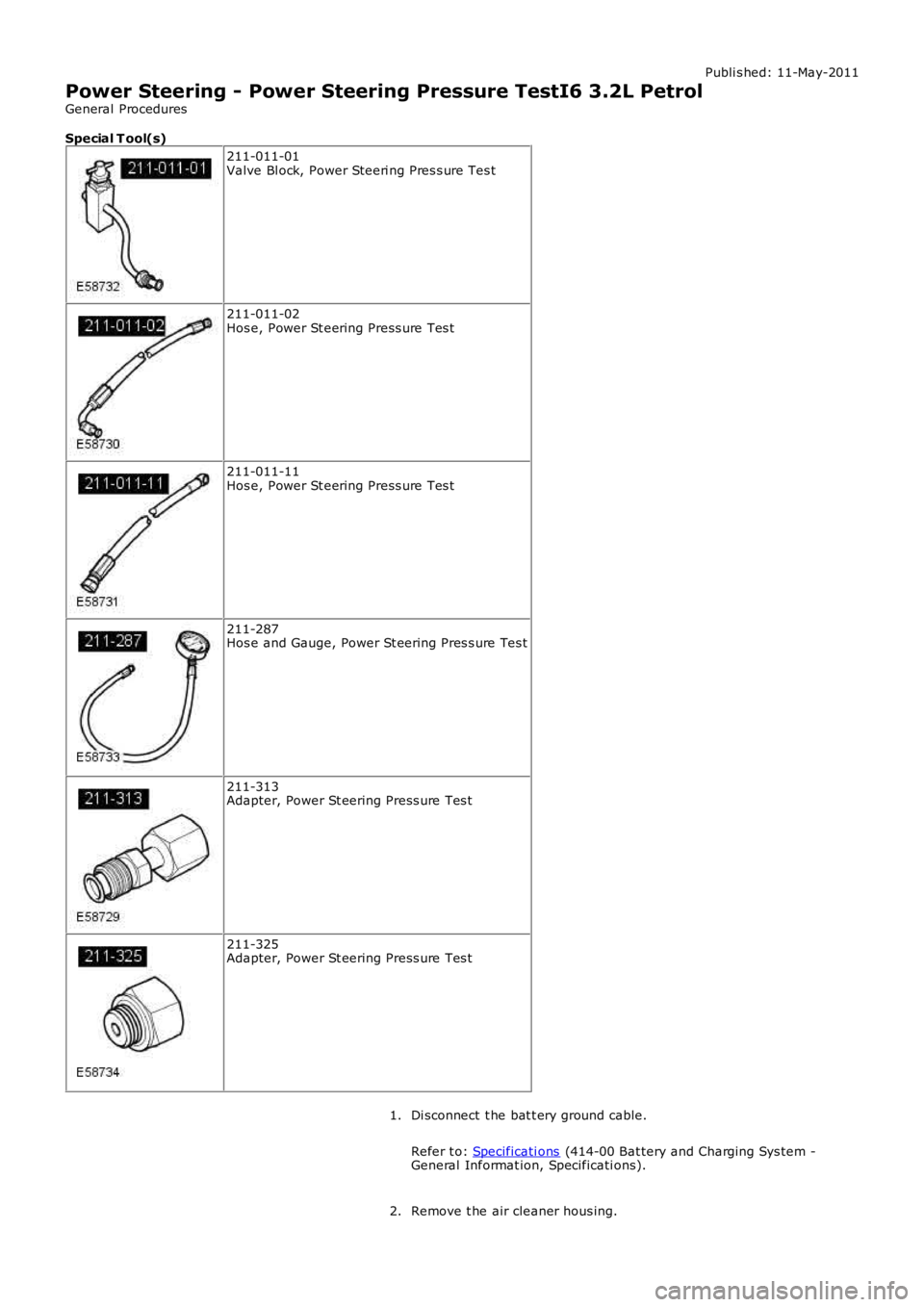
Publi s hed: 11-May-2011
Power Steering - Power Steering Pressure TestI6 3.2L Petrol
General Procedures
Special T ool(s) 211-011-01
Valve Bl ock, Power Steeri ng Pres s ure Tes t 211-011-02
Hos e, Power St eering Press ure Tes t 211-011-11
Hos e, Power St eering Press ure Tes t 211-287
Hos e and Gauge, Power St eering Pres s ure Tes t 211-313
Adapter, Power St eering Press ure Tes t 211-325
Adapter, Power St eering Press ure Tes t
Di sconnect t he bat t ery ground cable.
Refer t o: Specificati ons (414-00 Bat tery and Charging Sys tem -
General Informat ion, Specificati ons).
1.
Remove t he air cleaner hous ing.
2.