LAND ROVER FRELANDER 2 2006 Repair Manual
FRELANDER 2 2006
LAND ROVER
LAND ROVER
https://www.carmanualsonline.info/img/64/57251/w960_57251-0.png
LAND ROVER FRELANDER 2 2006 Repair Manual
Trending: start stop button, fuse box, ground clearance, light, child restraint, weight, power steering fluid
Page 571 of 3229
Publi s hed: 11-May-2011
Steering Column - Steering Column
Des cript ion and Operat ion
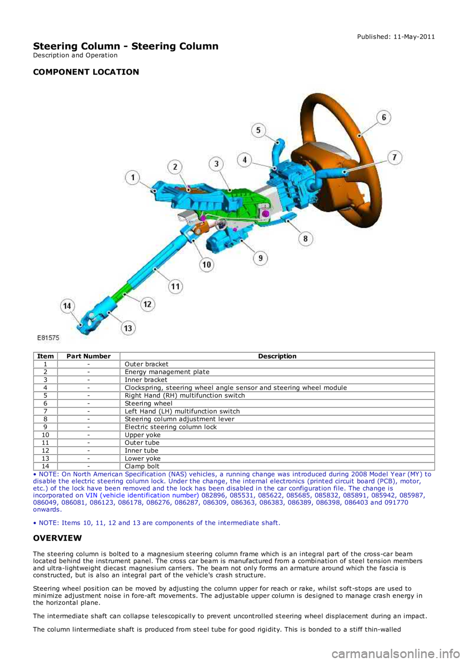
COMPONENT LOCATION
ItemPart NumberDescription
1-Out er bracket2-Energy management plat e
3-Inner bracket
4-Cl ocks pri ng, s t eering wheel angl e s ensor and s teering wheel modul e5-Ri ght Hand (RH) mul ti functi on swit ch
6-St eeri ng wheel
7-Left Hand (LH) mul ti funct ion swi tch8-St eeri ng col umn adjus tment l ever
9-El ect ri c s teeri ng column l ock
10-Upper yoke11-Out er tube
12-Inner tube
13-Lower yoke14-Cl amp bolt
• NOTE: On North Ameri can Specificat ion (NAS) vehi cles , a running change was int roduced during 2008 Model Y ear (MY ) t odis able t he electric st eering col umn lock. Under t he change, the i nternal elect ronics (print ed circuit board (PCB), motor,etc.) of t he l ock have been removed and t he lock has been dis abled i n t he car configurat ion fi le. The change i sincorporat ed on VIN (vehi cl e identi fi cat ion number) 082896, 085531, 085622, 085685, 085832, 085891, 085942, 085987,086049, 086081, 086123, 086178, 086276, 086287, 086309, 086363, 086383, 086389, 086398, 086403 and 091770onwards .
• NOTE: Items 10, 11, 12 and 13 are components of t he i nt ermedi ate s haft .
OVERVIEW
The s teeri ng column i s bolt ed to a magnesi um s t eering column frame whi ch is an i ntegral part of t he cros s -car beamlocated behind the i nst rument panel. The cros s car beam is manufact ured from a combinati on of s teel tens ion membersand ult ra-li ght weight diecas t magnes ium carri ers . The beam not onl y forms an armature around whi ch the fasci a iscons t ructed, but is al so an int egral part of the vehicle's crash s truct ure.
Steering wheel pos it ion can be moved by adjust ing the column upper for reach or rake, whi ls t s oft -s tops are us ed tomi ni mi ze adjust ment nois e i n fore-aft movement s. The adjus t abl e upper column is des igned t o manage cras h energy i nt he horizontal plane.
The int ermediat e s haft can collaps e t eles copicall y to prevent uncont rol led s t eering wheel dis placement during an i mpact .
The col umn l int ermediat e s haft is produced from s teel tube for good rigi dit y. This is bonded to a s ti ff t hin-wal led
Page 572 of 3229
elas tomer t o i sol at e road nois e.
IMPACT PROTECTION
In a s eri ous impact, t he s teeri ng column i s desi gned to manage two si mult aneous event s ; the intermediat e s haft mus tis olat e t he s teeri ng wheel from any movement of t he s t eering rack (i f the angle of the s teering wheel changes it wi ll affectt he way in which t he airbag deploys t owards t he dri ver).
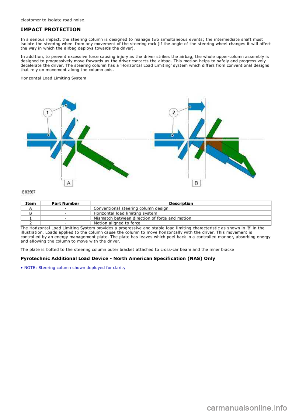
In addi ti on, t o prevent exces s ive force caus ing injury as t he dri ver s trikes t he airbag, t he whole upper-col umn as s embl y i sdesi gned to progres si vel y move forwards as the driver cont act s t he airbag. This mot ion hel ps to safely and progress ivelydecel erate the driver. The s t eering column has a 'Horizont al Load Li mit ing' s ys t em whi ch di ffers from conventi onal des ignst hat rely on movement along t he column axis .
Hori zont al Load Limit ing Sys tem
ItemPart NumberDescriptionA-Convent ional s teeri ng col umn des ign
B-Horizontal load l imi ti ng s yst em
1-Mis match bet ween direct ion of force and moti on2-Mot ion al igned t o force
The Hori zont al Load Limit ing Sys tem provides a progress i ve and st able l oad li mit ing characteris ti c as s hown in 'B' in theil lus trati on. Loads appl ied t o t he column cause the column to move hori zont al ly wit h the driver. Thi s movement i scont rol led by an energy management plat e. The pl ate has l eaves whi ch peel back in a cont roll ed manner, absorbing energyand all owing t he col umn t o move wi th the driver.
The plat e is bol ted t o t he s teering column out er bracket at tached to cross -car beam and t he i nner bracke
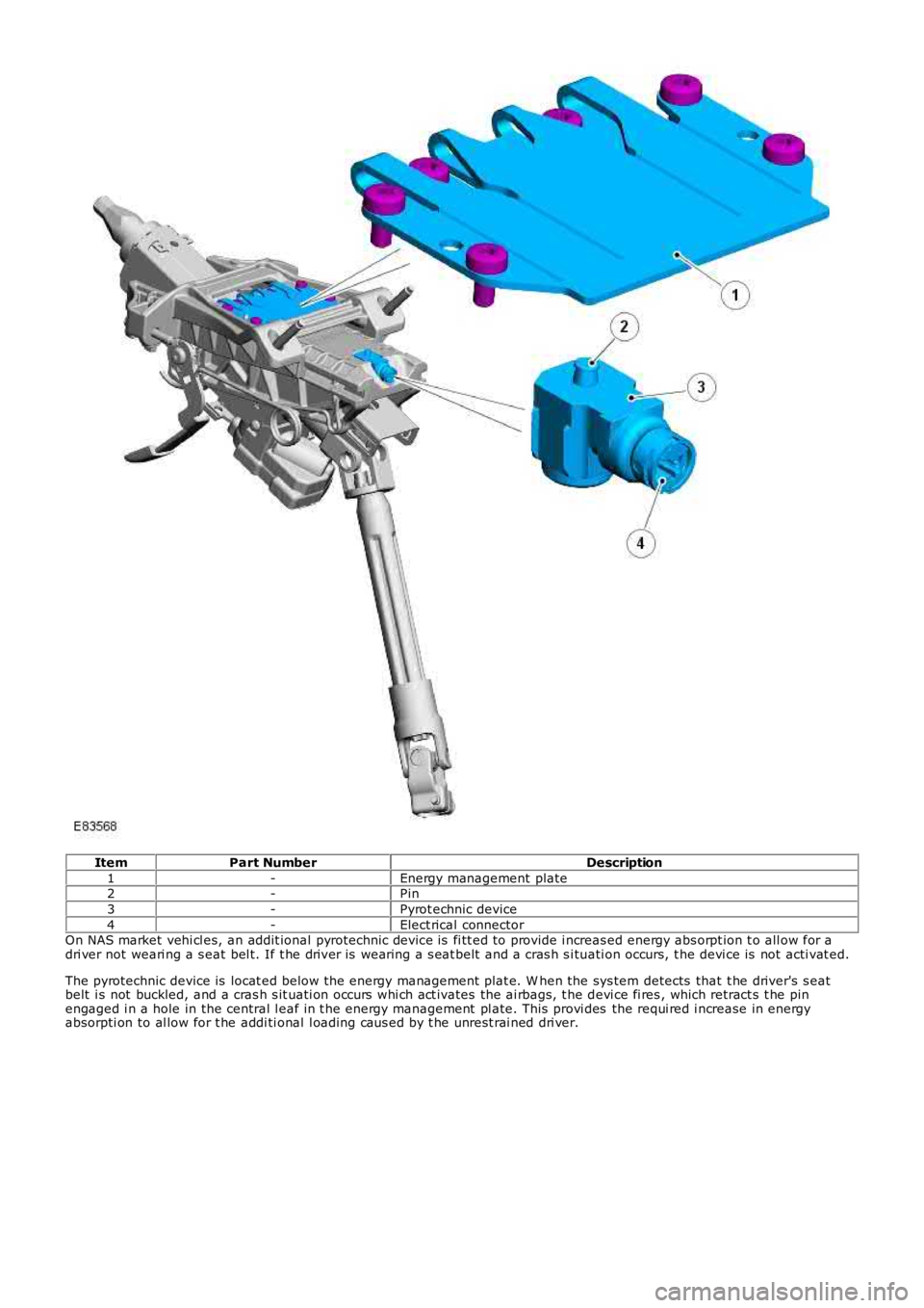
Pyrotechnic Additional Load Device - North American Specification (NAS) Only
• NOTE: Steering column shown deployed for clarit y
Page 573 of 3229
ItemPart NumberDescription
1-Energy management plate2-Pin
3-Pyrot echnic device
4-Elect rical connectorOn NAS market vehi cl es, an addit ional pyrotechnic device is fi tt ed to provide i ncreas ed energy abs orpt ion t o all ow for adri ver not weari ng a s eat bel t. If t he driver is wearing a s eat belt and a cras h s i tuati on occurs, t he devi ce is not acti vat ed.
The pyrotechnic device is locat ed below the energy management plat e. W hen the sys tem detects that t he driver's s eatbelt i s not buckled, and a cras h s it uati on occurs whi ch act ivates the ai rbags, t he devi ce fi res , which retract s t he pinengaged i n a hole in the central l eaf in t he energy management pl ate. This provi des the requi red i ncrease in energyabsorpti on to al low for t he addi ti onal l oading caus ed by t he unrest rai ned dri ver.
Page 574 of 3229
Publi s hed: 11-May-2011
Steering Column - Steering Column
Diagnosi s and Tes ti ng
For addit ional informat ion.
REFER to: St eering Sys tem (211-00 Steeri ng Sys t em - General Informati on, Di agnos is and Tes ti ng).
Page 575 of 3229
Publi s hed: 11-May-2011
Steering Column - Steering Wheel
Removal and Inst all ati on
Removal
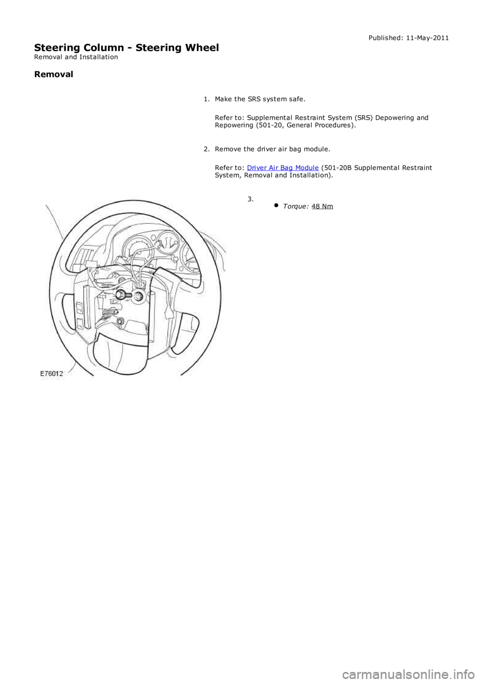
Make t he SRS s ys t em s afe.
Refer t o: Supplement al Res t raint Sys tem (SRS) Depowering and
Repowering (501-20, General Procedures ).
1.
Remove t he dri ver air bag modul e.
Refer t o: Dri ver Ai r Bag Modul e (501-20B Supplement al Res t raint
Syst em, Removal and Ins tall ati on).
2.
T orque: 48 Nm 3.
Page 576 of 3229
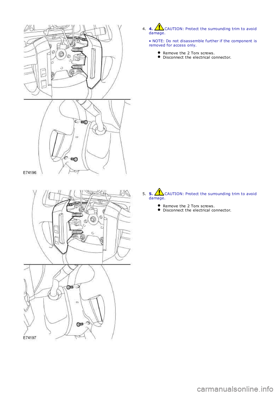
4. CAUTION: Prot ect t he s urroundi ng trim t o avoi ddamage.
• NOTE: Do not di sas s emble furt her i f the component isremoved for acces s onl y.
Remove t he 2 Torx screws .Di sconnect t he electrical connect or.
4.
5. CAUTION: Prot ect t he s urroundi ng trim t o avoi ddamage.
Remove t he 2 Torx screws .Di sconnect t he electrical connect or.
5.
Page 577 of 3229
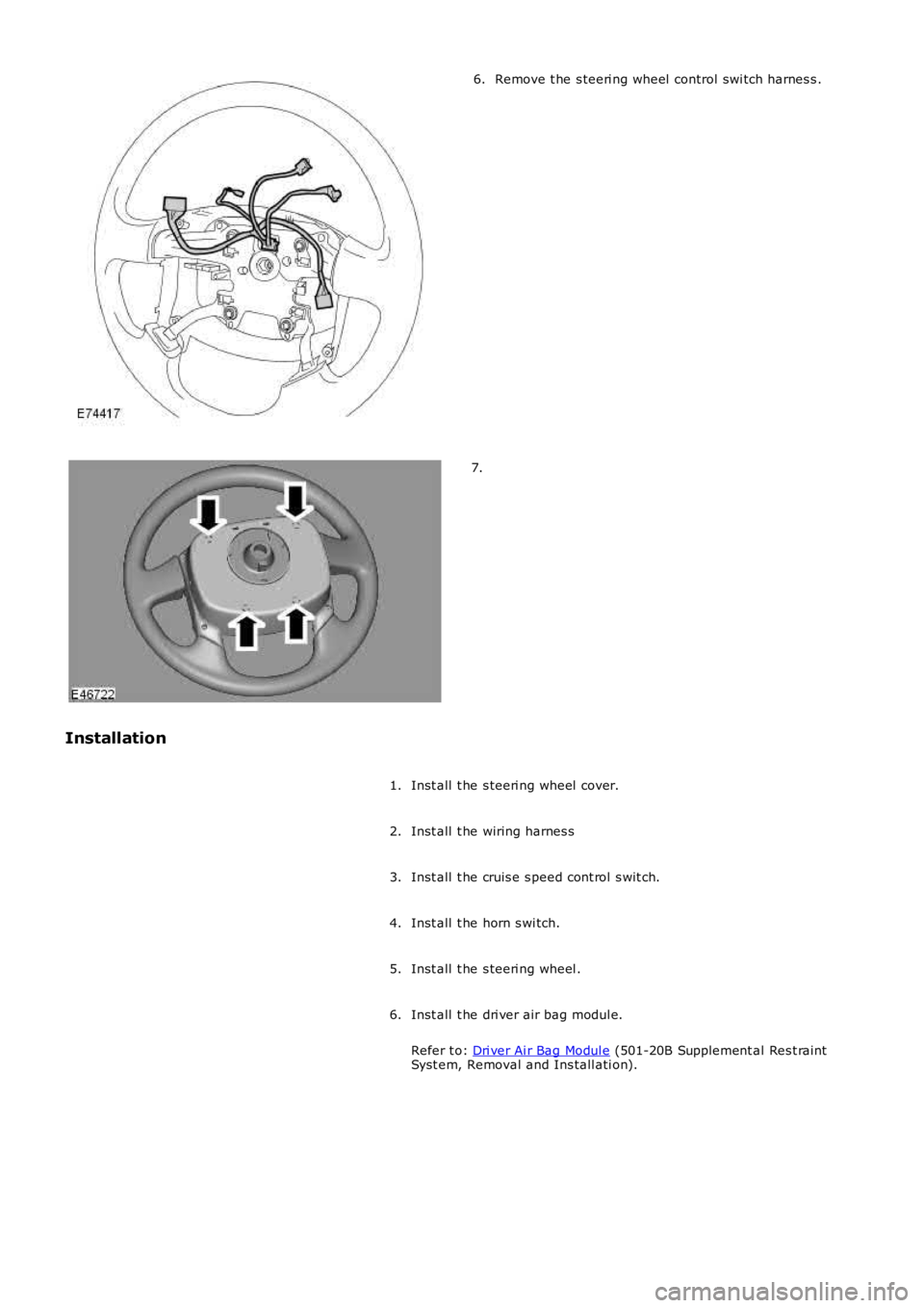
Remove t he s teeri ng wheel control swi tch harnes s .6.
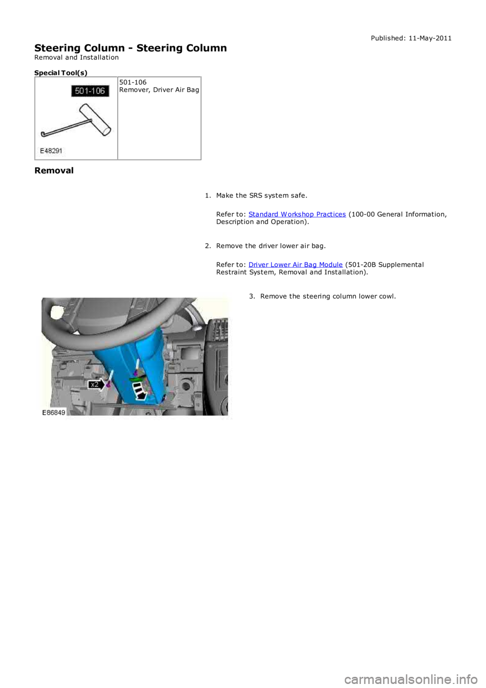
7.
Installation
Inst all t he s teeri ng wheel cover.1.
Inst all t he wiring harnes s2.
Inst all t he cruis e s peed cont rol s wit ch.3.
Inst all t he horn s wi tch.4.
Inst all t he s teeri ng wheel .5.
Inst all t he dri ver air bag modul e.
Refer t o: Dri ver Ai r Bag Modul e (501-20B Supplement al Res t raintSyst em, Removal and Ins tall ati on).
6.
Page 578 of 3229
Publi s hed: 11-May-2011
Steering Column - Steering Column
Removal and Inst all ati on
Special T ool(s)
501-106Remover, Driver Air Bag
Removal
Make t he SRS s ys t em s afe.
Refer t o: Standard W orks hop Pract ices (100-00 General Informat ion,Des cript ion and Operat ion).
1.
Remove t he dri ver l ower ai r bag.
Refer t o: Dri ver Lower Air Bag Module (501-20B SupplementalRes traint Sys t em, Removal and Inst all at ion).
2.
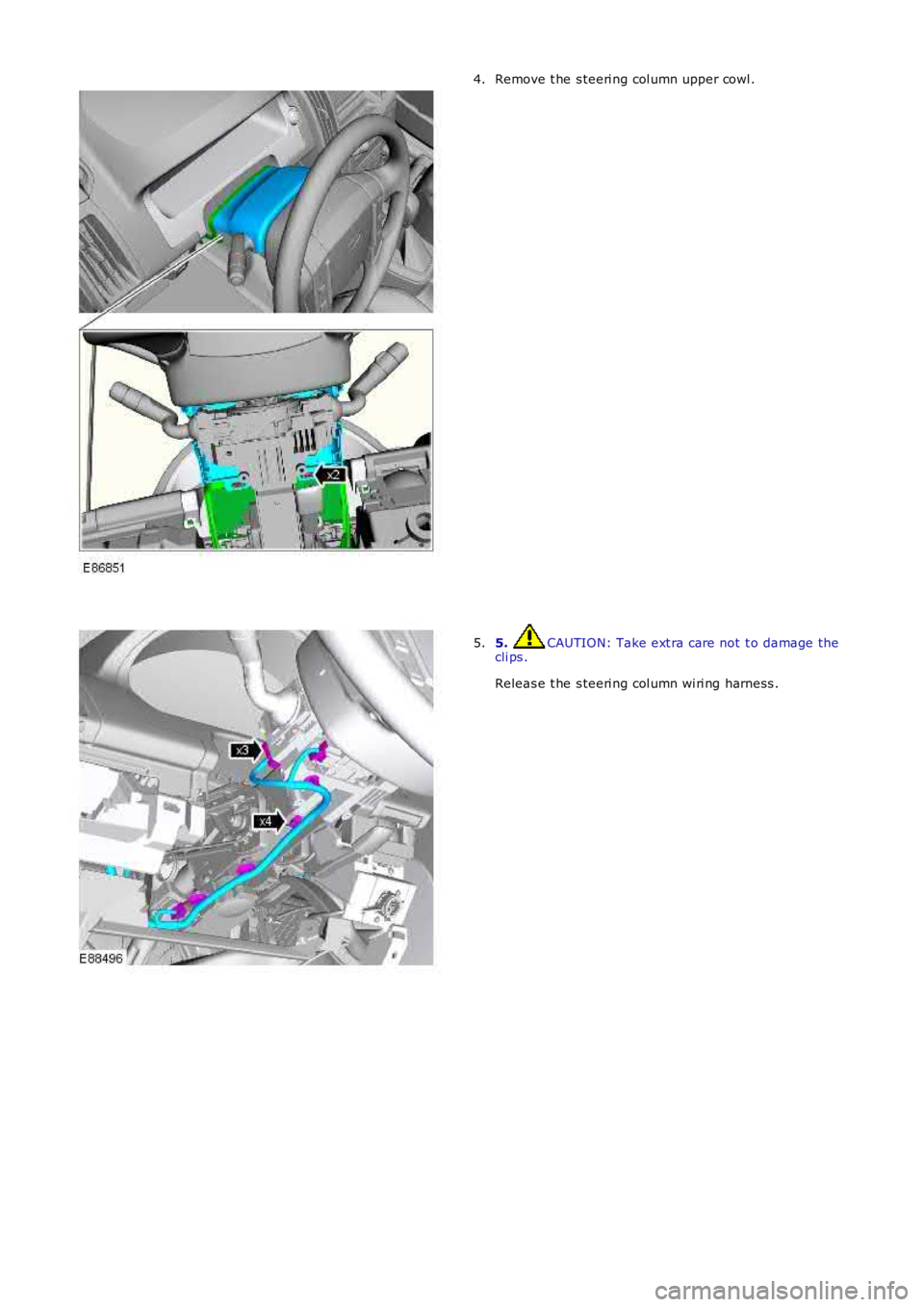
Remove t he s teeri ng col umn l ower cowl.3.
Page 579 of 3229
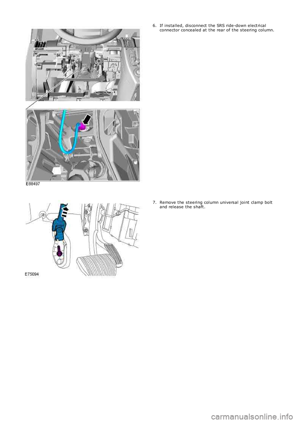
Remove t he s teeri ng col umn upper cowl .4.
5. CAUTION: Take ext ra care not t o damage thecli ps .
Releas e t he s teeri ng col umn wi ri ng harness .
5.
Page 580 of 3229
If ins tal led, di s connect t he SRS ride-down el ect ri calconnector concealed at t he rear of t he s teeri ng col umn.6.
Remove t he s teeri ng col umn univers al joi nt cl amp boltand rel ease the s haft .7.
Trending: brake, seats, refrigerant type, fuel cap release, tire size, spark plugs, cabin filter


