LAND ROVER FRELANDER 2 2006 Repair Manual
FRELANDER 2 2006
LAND ROVER
LAND ROVER
https://www.carmanualsonline.info/img/64/57251/w960_57251-0.png
LAND ROVER FRELANDER 2 2006 Repair Manual
Trending: brake, brake fluid, cabin filter, audio, rear entertainment, deactivate airbag, water pump
Page 591 of 3229
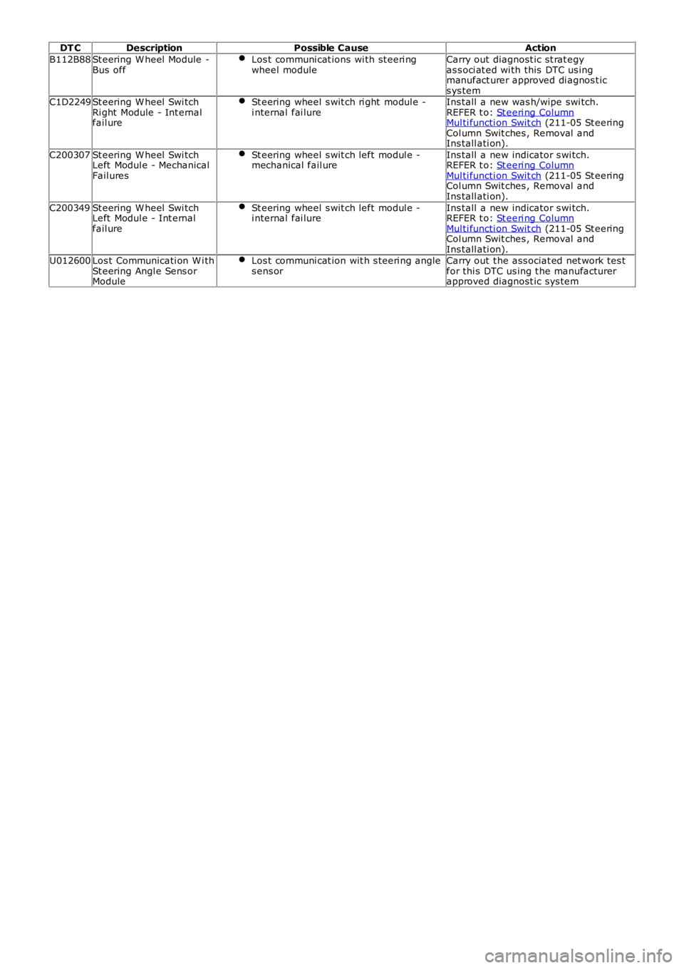
DT CDescriptionPossible CauseAction
B112B88St eering W heel Module -Bus offLos t communi cat ions wi th st eeri ngwheel moduleCarry out diagnost ic st rat egyas s oci at ed wi th this DTC us ingmanufact urer approved di agnos t ics ys temC1D2249St eering W heel Swi tchRi ght Module - Int ernalfail ure
St eering wheel s wit ch ri ght modul e -i nternal fai lureIns tall a new was h/wipe swi tch.REFER t o: St eeri ng ColumnMul ti functi on Swit ch (211-05 St eeringCol umn Swit ches , Removal andIns tall ati on).
C200307St eering W heel Swi tchLeft Modul e - MechanicalFail ures
St eering wheel s wit ch left modul e -mechanical fail ureIns tall a new indicator s wi tch.REFER t o: St eeri ng ColumnMul ti functi on Swit ch (211-05 St eeringCol umn Swit ches , Removal andIns tall ati on).
C200349St eering W heel Swi tchLeft Modul e - Int ernalfail ure
St eering wheel s wit ch left modul e -i nternal fai lureIns tall a new indicator s wi tch.REFER t o: St eeri ng ColumnMul ti functi on Swit ch (211-05 St eeringCol umn Swit ches , Removal andIns tall ati on).U012600Los t Communicati on W i thSt eering Angl e Sens orModule
Los t communi cat ion wit h s teeri ng angles ens orCarry out t he ass ociat ed net work tes tfor thi s DTC us ing t he manufacturerapproved diagnost ic sys tem
Page 592 of 3229
Publi s hed: 11-May-2011
Steering Column Switches - Steering Column Multifunction Switch
Removal and Inst all ati on
Removal
• NOTE: Removal of t he winds hield wiper s wit ch ass embly is i dent ical to this procedure.
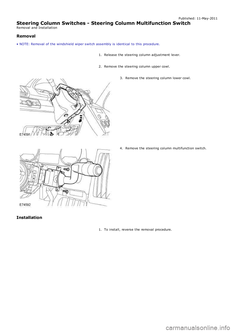
Releas e t he s teeri ng col umn adjus t ment lever.1.
Remove t he s teeri ng col umn upper cowl .2.
Remove t he s teeri ng col umn l ower cowl.3.
Remove t he s teeri ng col umn mul ti functi on swit ch.4.
Installation
To i nst all , revers e t he removal procedure.1.
Page 593 of 3229
Publi s hed: 11-May-2011
Steering Column Switches - Ignition Switch
Removal and Inst all ati on
Removal
Make t he SRS s ys t em s afe.
Refer t o: Standard W orks hop Pract ices (100-00 General Informat ion,Des cript ion and Operat ion).
1.
Remove t he dri ver l ower ai r bag modul e.
Refer t o: Dri ver Lower Air Bag Module (501-20B SupplementalRes traint Sys t em, Removal and Inst all at ion).
2.
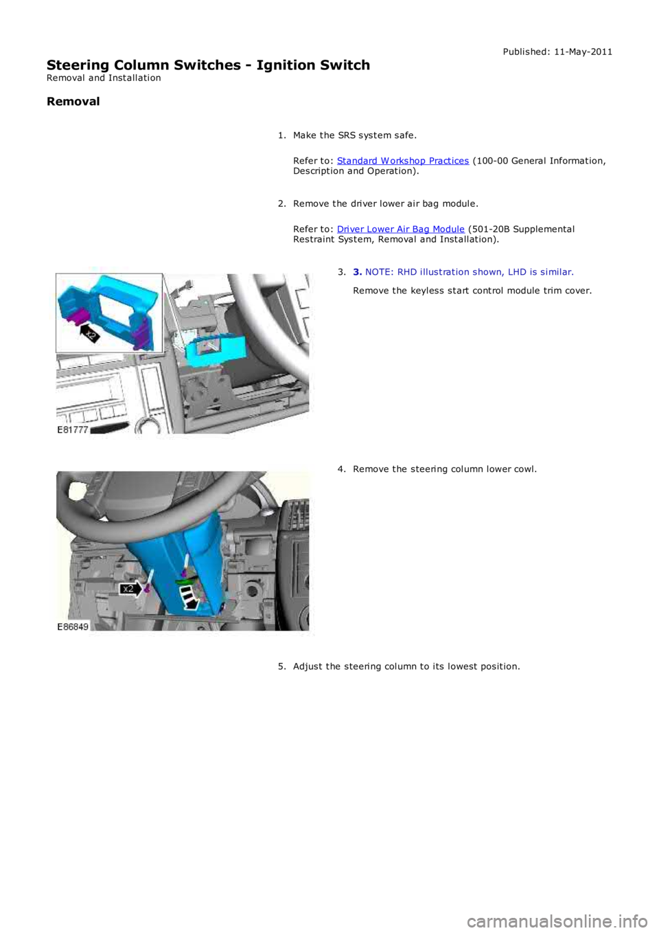
3. NOTE: RHD i llus t rat ion s hown, LHD is s i mil ar.
Remove t he keyl es s s t art cont rol module trim cover.
3.
Remove t he s teeri ng col umn l ower cowl.4.
Adjus t t he s teeri ng col umn t o i ts l owest pos it ion.5.
Page 594 of 3229
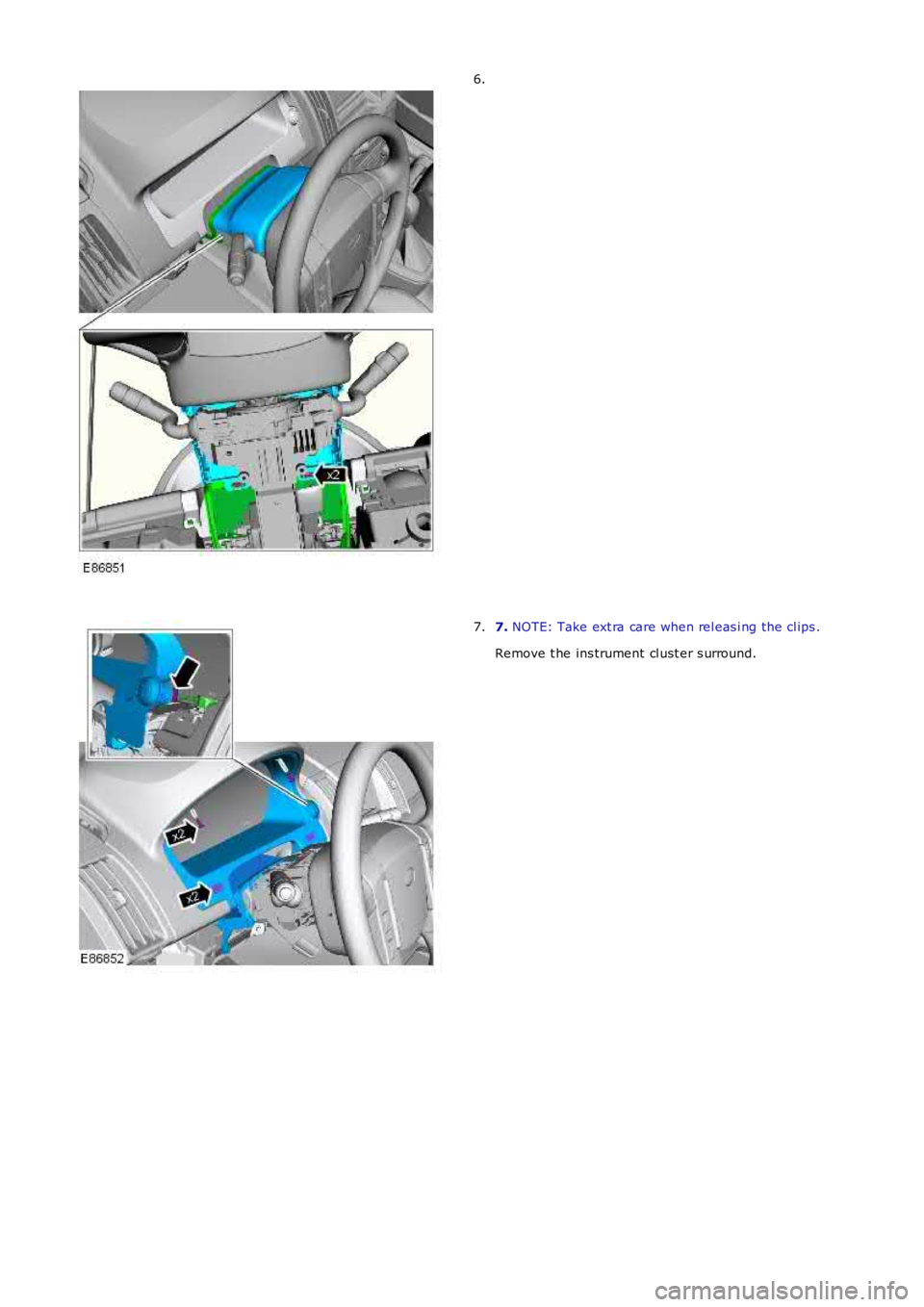
6.
7. NOTE: Take ext ra care when rel eas i ng the cl ips .
Remove t he ins trument cl ust er s urround.
7.
Page 595 of 3229
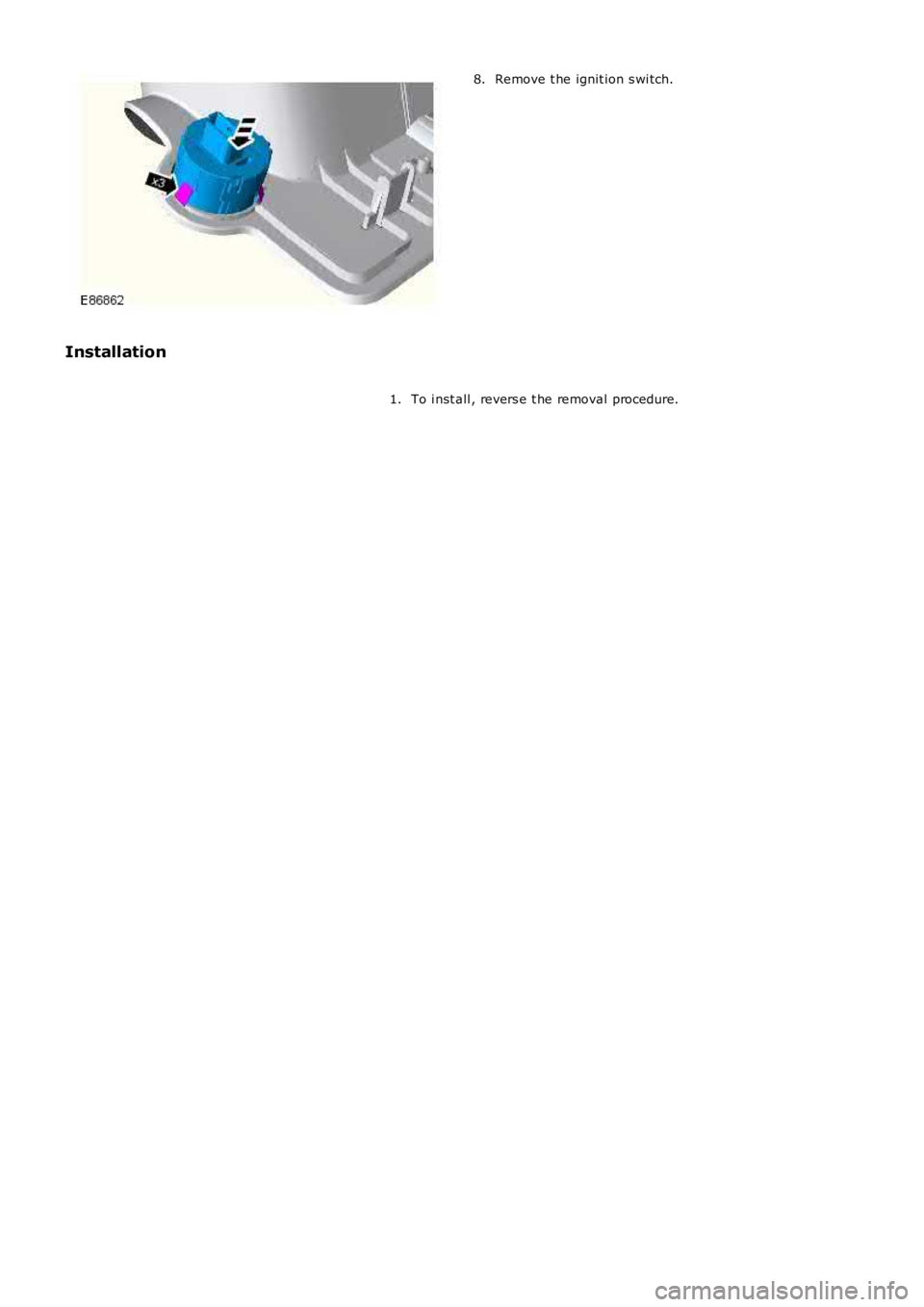
Remove t he ignit ion s wi tch.8.
Installation
To i nst all , revers e t he removal procedure.1.
Page 596 of 3229
Publi s hed: 11-May-2011
Steering Column Switches - Steering Column Lock Module
Removal and Inst all ati on
Removal
• NOTE: On vehicles bui lt from VIN 091770 t he s teeri ng col umn l ock modul e may be a non-functi onal component .
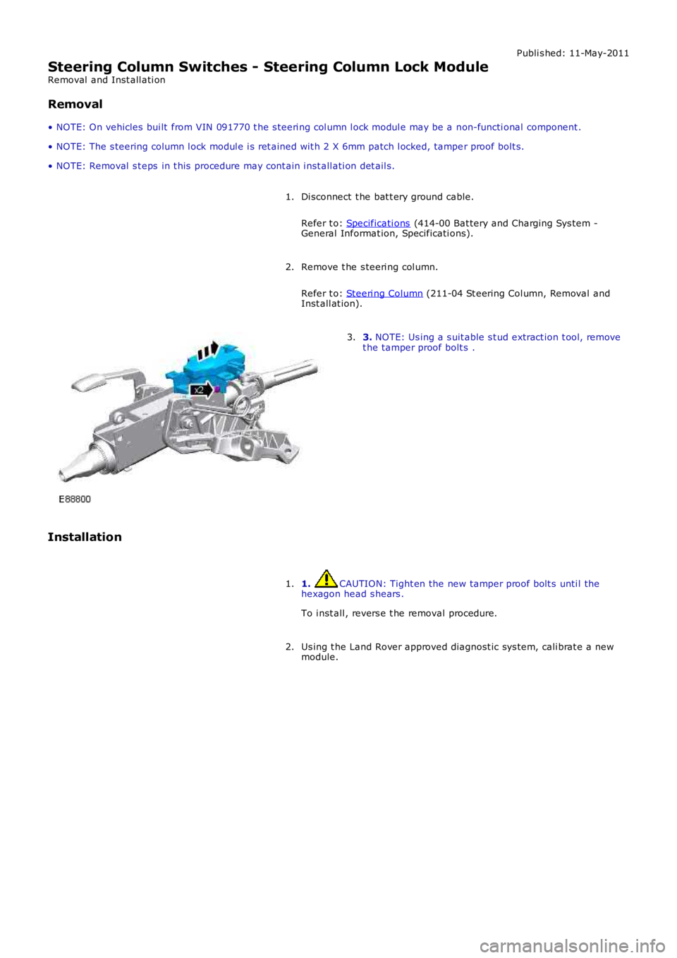
• NOTE: The s teering column l ock modul e i s ret ained wit h 2 X 6mm patch l ocked, tamper proof bolt s.
• NOTE: Removal s t eps in t his procedure may cont ain i nst all ati on det ail s.
Di sconnect t he bat t ery ground cable.
Refer t o: Specificati ons (414-00 Bat tery and Charging Sys tem -General Informat ion, Specificati ons).
1.
Remove t he s teeri ng col umn.
Refer t o: Steeri ng Column (211-04 St eering Col umn, Removal andInst all at ion).
2.
3. NOTE: Us ing a s uit able s t ud extract ion t ool, removet he tamper proof bolt s .3.
Installation
1. CAUTION: Tight en the new tamper proof bolt s unti l thehexagon head s hears .
To i nst all , revers e t he removal procedure.
1.
Us ing t he Land Rover approved diagnost ic sys tem, cali brat e a newmodule.2.
Page 597 of 3229
Publi s hed: 11-May-2011
Engine System - General Information - Engine
Diagnosi s and Tes ti ng
For addit ional informat ion. REFER t o:
Engi ne (303-01A Engine - I6 3.2L Petrol, Diagnos is and Tes ti ng),Engi ne (303-01B Engine - TD4 2.2L Di esel , Diagnos is and Tes t ing).
Page 598 of 3229
Publi s hed: 11-May-2011
Engine System - General Information - Cylinder Head Gasket SelectionTD4
2.2L Diesel
General Procedures
Special T ool(s) 303-979
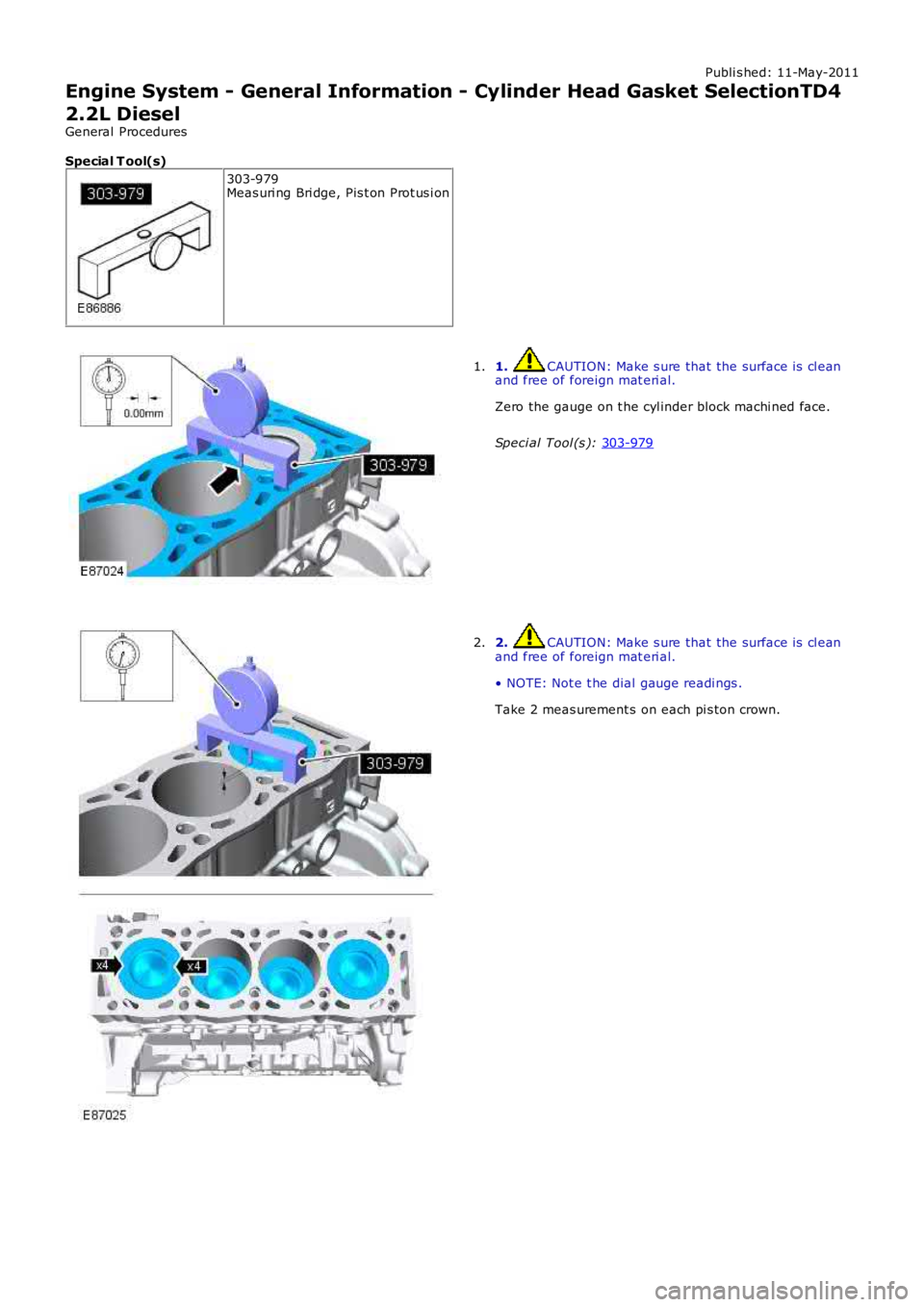
Meas uri ng Bri dge, Pis t on Prot us i on 1. CAUTION: Make s ure that the surface is cl ean
and free of foreign mat eri al.
Zero the gauge on t he cyl inder block machi ned face.
Speci al Tool (s ): 303-979 1.
2. CAUTION: Make s ure that the surface is cl ean
and free of foreign mat eri al.
• NOTE: Not e t he dial gauge readi ngs .
Take 2 meas urement s on each pi s ton crown.
2.
Page 599 of 3229
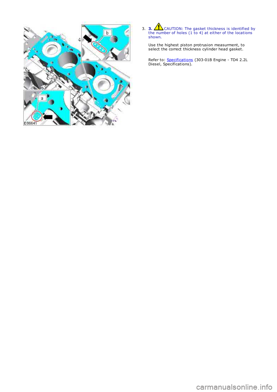
3. CAUTION: The gas ket t hicknes s i s identi fi ed byt he number of holes (1 t o 4) at eit her of t he l ocat ionss hown.
Us e t he highest pi s ton prot rus i on measurment, t os elect the correct thicknes s cyli nder head gasket .
Refer t o: Specificati ons (303-01B Engine - TD4 2.2LDi es el, Specifi cat ions ).
3.
Page 600 of 3229
Publ is hed: 02-Jun-2011
Engine System - General Information - Leakage Test Using Smoke Test
Equipment
General Procedures
CAUTION: The compres s ed air li ne s uppl y pres s ure mus t be bet ween 3.5 and 12 bar (50 and 175 psi ) for t he s moket es t equipment t o functi on correctl y. Do not exceed t hi s pres s ure. Fai lure t o fol low t his ins truct ion may res ult in damage tot he smoke tes t equi pment.
• NOTE: The vehi cle bat tery mus t be in good condit ion and ful ly charged before carryi ng out thi s procedure.
• NOTE: On vehicles wit h 3.0L TDV6, it wi ll be necess ary to ins ert s moke at bot h ai r cl eaner outl et pi pes independentl y ift he ri ght hand t urbocharger and as s oci at ed hos es are t o be t es ted.
• NOTE: In s ome cases i t may be necess ary to remove undert rays, t ri m or engine covers t o obt ai n acces s t o all potent ialleak l ocat ions.
• NOTE: Some vari ati on in the i ll us t rat ions may occur, but the es s ent ial informat ion i s always correct .
• NOTE: For furt her informati on regardi ng operati on of the tes t equi pment refer t o the manufacturers operat ors manuals uppl ied wi th the ki t.
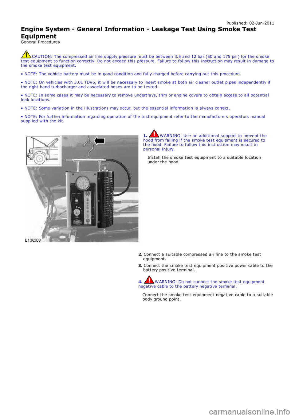
1. W ARNING: Use an addi ti onal s upport to prevent t hehood from fall ing i f the s moke t es t equi pment i s s ecured tot he hood. Fail ure t o follow thi s ins truct ion may res ult i npers onal i njury.
Ins tal l t he s moke t est equipment t o a s uit able l ocat ionunder the hood.
2. Connect a s uit abl e compres sed ai r li ne to the s moke t es tequipment.
3. Connect the s moke t est equipment pos it ive power cabl e to thebatt ery pos it ive t erminal.
4. W ARNING: Do not connect t he s moke tes t equipmentnegat ive cable t o t he batt ery negati ve terminal.
Connect t he s moke tes t equipment negat ive cable t o a sui tablebody ground point .
Trending: change wheel, brake sensor, light, climate settings, bulb, emergency key access, phone

