LAND ROVER FRELANDER 2 2006 Repair Manual
Manufacturer: LAND ROVER, Model Year: 2006, Model line: FRELANDER 2, Model: LAND ROVER FRELANDER 2 2006Pages: 3229, PDF Size: 78.5 MB
Page 761 of 3229
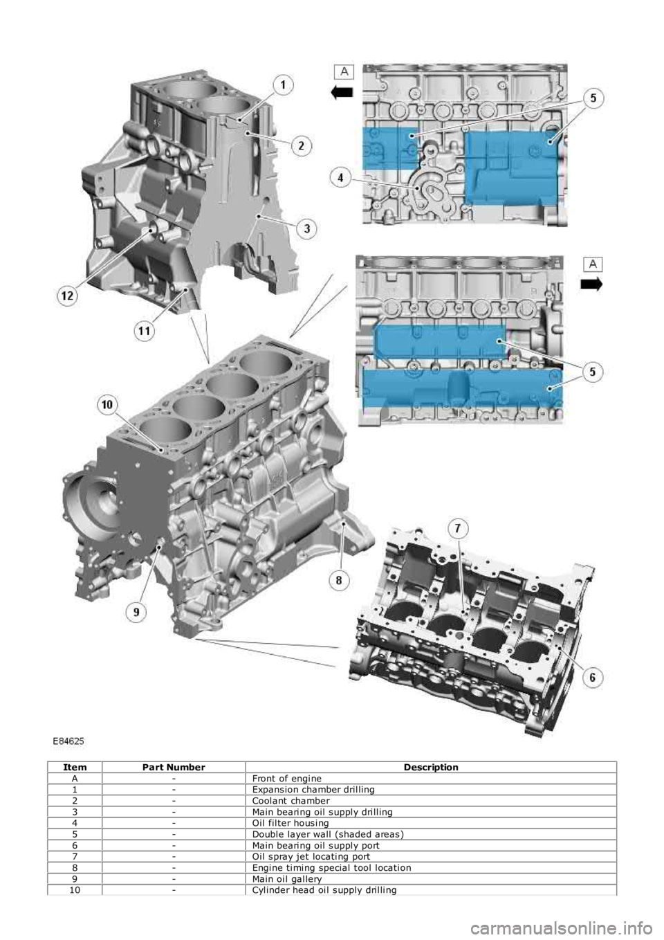
ItemPart NumberDescription
A-Front of engi ne1-Expans ion chamber dril ling
2-Cool ant chamber
3-Main beari ng oil s uppl y dri ll ing4-Oil fil ter hous i ng
5-Doubl e layer wall (shaded areas )
6-Main beari ng oil s uppl y port7-Oil s pray jet locati ng port
8-Engi ne ti mi ng special t ool l ocati on
9-Main oi l gal lery10-Cyl inder head oi l s upply dril li ng
Page 762 of 3229
11-VGT oil return port
12-VGT oil s uppl y port
The cyl inder block is manufact ured from cas t -i ron and feat ures double layer wal ls t hat provide high st rengt h and ri gidit y.An air cus hion i s formed between t he l ayers and als o acts t o reduce t he NVH l evel s produced by the engine. The blockfeat ures 5 bol ted mai n beari ng journals that als o provi de high s t rength and rigi dit y to the l ower end of t he engine.
The cyl inders are direct ly bored int o t he cyl inder bl ock and do not require cyl inder liners. Two gui de s leeves are l ocated int he cyl inder bl ock, and provided t o correct ly al ign t he cyl inder head and gas ket to the cyli nder block.
A hole formed in the LH rear of the cyli nder bl ock below the st art er motor, provides the locat ion for an engine t imi ngs pecial t ool . W hen i nserted, the special tool locates i n a corres ponding hol e in the flywheel to temporaril y hol d t hecrankshaft wit h No. 1 pis t on at the Top Dead Cent er (TDC) posi ti on.
The oil filt er and cool er hous ing, and main oi l gal lery are locat ed on t he LH s ide of t he cylinder block. The mai n oil gall eryis a longit udinal dril li ng that runs t he l engt h of the cyli nder bl ock, and s uppl ies pres s urized oi l to al l the engine movi ngcomponents . Pres s uri zed oi l is di verted from t he main oi l gal lery to s upply the main and bi g-end bearings via diagonal oildri ll ings in the cyli nder block, and in t he crankshaft journals . The mai n oil gall ery i s s eal ed at each end wit h a s crewedplug.
A cros s dril ling above No. 2 mai n beari ng direct s pres surized oil from the main oi l gal lery to a port at t he Right-Hand (RH)s ide of t he cyl inder bl ock. The port s upplies press urized oil via a banjo t ype connect ion to t he VGT beari ngs. Ret urn oi lfrom the VGT is direct ed via a pipe and a connect ion at the RH si de of the bl ock, i nt o t he oil pan. A vert ical dril li ng at theLH front of the cyli nder bl ock s upplies press uri zed oil from the mai n oil gall ery, up t o a corresponding oi l gal lery in t hecyl inder head.
Engi ne cool ing i s achi eved wit h int er-cyl inder coolant chambers and expans ion chamber dril li ngs , formed i n t he cyl inderblock cool ant jacket . The coolant chambers direct coolant t hrough openings i n t he block upper s urface to the cyli nder head.Core pl ugs seal t he ext eri or openings formed i n t he cyl inder block coolant jacket.
Oil Spray Jets
Page 763 of 3229
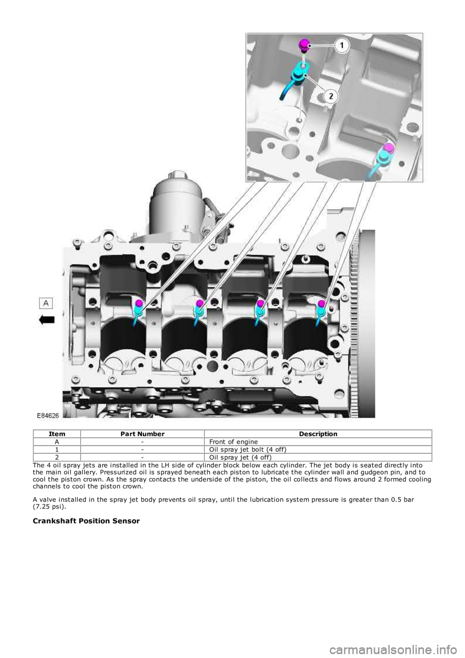
ItemPart NumberDescription
A-Front of engine1-Oil s pray jet bol t (4 off)
2-Oil s pray jet (4 off)
The 4 oi l s pray jet s are i nst all ed in the LH si de of cyl inder bl ock bel ow each cyl inder. The jet body i s s eat ed direct ly i ntot he main oi l gal lery. Pres s uri zed oi l is s prayed beneat h each pis t on to lubri cat e t he cyl inder wall and gudgeon pin, and t ocool t he pis t on crown. As the spray cont act s t he undersi de of the pi st on, the oi l col lect s and flows around 2 formed cool ingchannels t o cool the pi st on crown.
A valve i nst all ed in the s pray jet body prevent s oil s pray, unti l the l ubricati on s ys t em press ure is great er than 0.5 bar(7.25 ps i).
Crankshaft Position Sensor
Page 764 of 3229
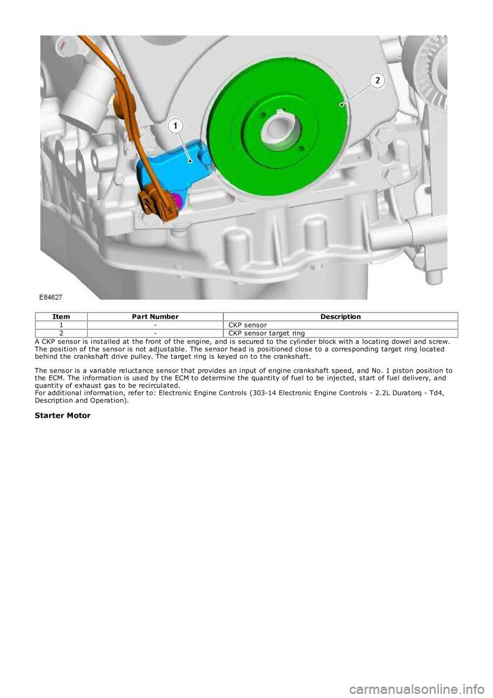
ItemPart NumberDescription
1-CKP s ens or2-CKP s ens or target ring
A CKP sens or is i ns t alled at the front of the engi ne, and i s s ecured to the cyli nder block wi th a locati ng dowel and s crew.The posi ti on of the sens or is not adjus table. The s ensor head is pos i ti oned clos e t o a corres ponding target ring l ocat edbehi nd t he cranks haft drive pull ey. The t arget ri ng is keyed on t o t he crankshaft.
The s ens or is a variabl e rel uct ance s ens or t hat provides an i nput of engi ne crankshaft speed, and No. 1 pis ton pos it ion tot he ECM. The informati on is us ed by t he ECM t o det ermi ne the quanti ty of fuel to be inject ed, s t art of fuel delivery, andquant it y of exhaus t gas to be recircul ated.For addit ional informat ion, refer t o: Electroni c Engi ne Controls (303-14 Electronic Engine Controls - 2.2L Durat orq - Td4,Des cript ion and Operat ion).
Starter Motor
Page 765 of 3229
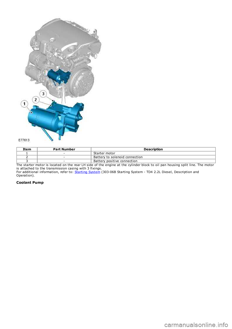
ItemPart NumberDescription
1-St art er motor2-Bat tery to sol enoi d connecti on
3-Bat tery pos i ti ve connect ion
The s tarter mot or is l ocat ed on the rear LH s ide of t he engi ne at t he cyl inder bl ock t o oi l pan hous ing s pli t li ne. The mot oris at t ached t o t he transmis si on casi ng wit h 3 fi xi ngs .For addit ional informat ion, refer t o: Starti ng Sys t em (303-06B Starti ng Syst em - TD4 2.2L Di es el, Des cri pt ion andOperat ion).
Coolant Pump
Page 766 of 3229
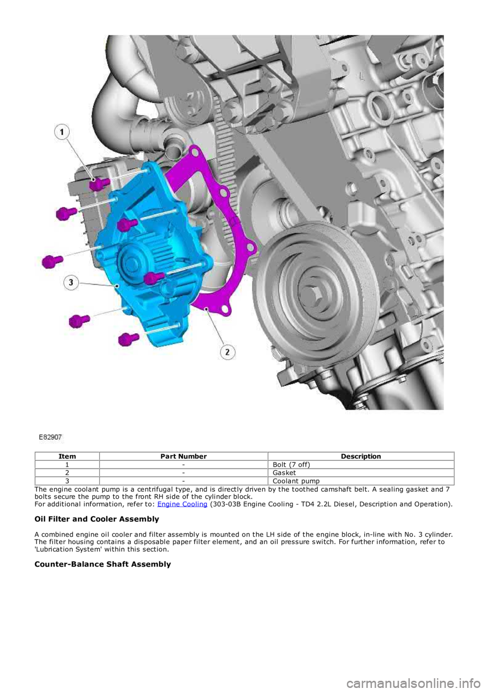
ItemPart NumberDescription
1-Bolt (7 off)2-Gas ket
3-Coolant pump
The engi ne cool ant pump is a cent ri fugal type, and is direct ly driven by t he t oot hed cams haft bel t. A s eal ing gas ket and 7bolt s s ecure the pump to the front RH si de of the cyli nder bl ock.For addit ional informat ion, refer t o: Engi ne Cooling (303-03B Engine Cooli ng - TD4 2.2L Dies el , Descripti on and Operat ion).
Oil Filter and Cooler Assembly
A combined engine oi l cooler and fil ter as sembl y is mount ed on t he LH s ide of t he engine block, in-line wit h No. 3 cylinder.The fi lt er hous ing contai ns a dis pos abl e paper fil ter element , and an oil pres s ure swi tch. For furt her i nformat ion, refer to'Lubri cat ion Sys tem' wi thin thi s s ect ion.
Counter-Balance Shaft Assembly
Page 767 of 3229
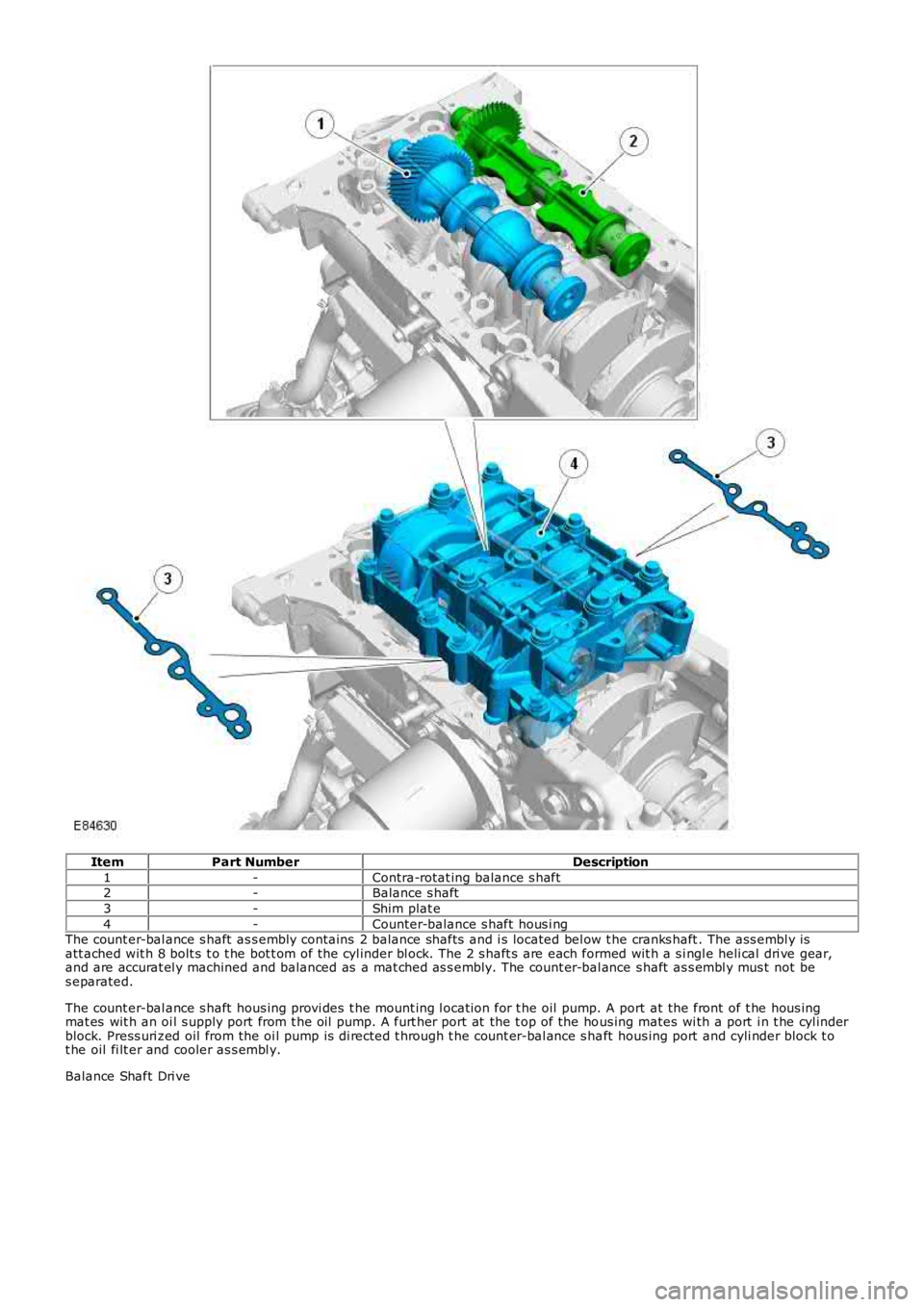
ItemPart NumberDescription
1-Contra-rotat ing balance s haft2-Balance s haft
3-Shim plat e
4-Counter-balance s haft hous i ngThe count er-bal ance s haft as s embly contains 2 balance shafts and i s located bel ow t he cranks haft . The ass embl y isatt ached wit h 8 bolt s t o t he bot t om of t he cyl inder bl ock. The 2 s haft s are each formed wit h a s i ngl e heli cal dri ve gear,and are accurat el y machined and balanced as a mat ched as s embly. The count er-bal ance s haft as s embl y mus t not bes eparated.
The count er-bal ance s haft hous ing provi des t he mount ing l ocati on for t he oil pump. A port at the front of t he hous ingmat es wit h an oi l s upply port from t he oil pump. A furt her port at the t op of the hous ing mates wi th a port i n t he cyl inderblock. Press uri zed oil from the oi l pump is di rected t hrough t he count er-bal ance s haft hous ing port and cyli nder block t ot he oil fi lt er and cooler as s embl y.
Balance Shaft Dri ve
Page 768 of 3229
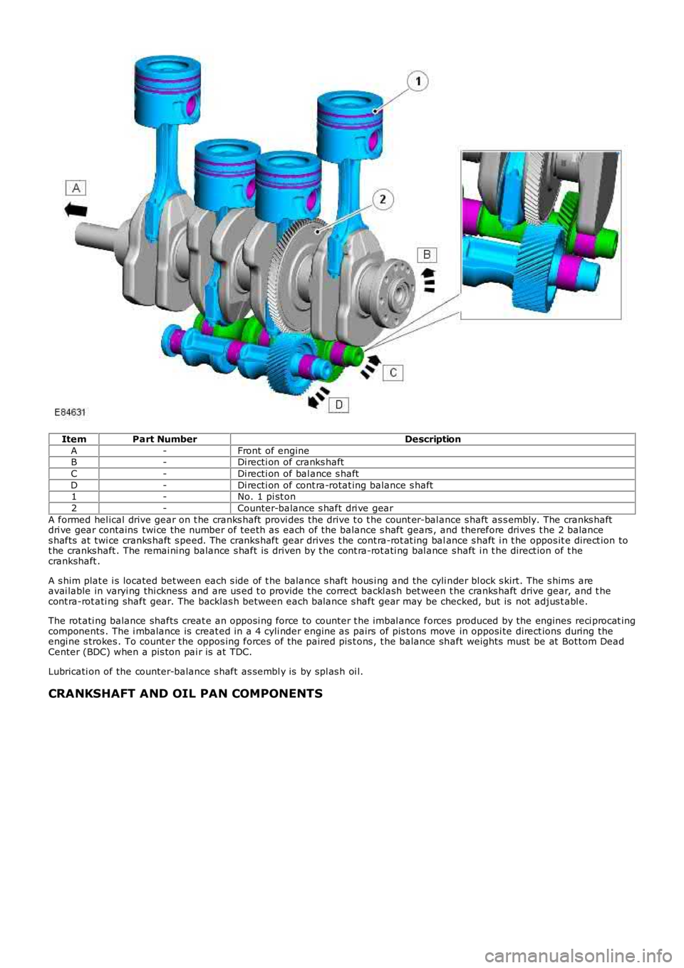
ItemPart NumberDescription
A-Front of engineB-Di recti on of cranks haft
C-Di recti on of bal ance s haft
D-Di recti on of cont ra-rotat ing balance s haft1-No. 1 pi st on
2-Counter-balance s haft dri ve gear
A formed hel ical drive gear on t he cranks haft provi des the drive t o t he count er-bal ance s haft as s embly. The cranks haftdri ve gear contains twi ce the number of teet h as each of the balance s haft gears , and therefore drives t he 2 balances hafts at twi ce cranks haft s peed. The cranks haft gear drives t he cont ra-rot at ing balance s haft i n t he oppos it e direct ion tot he cranks haft . The remai ni ng balance s haft is driven by t he cont ra-rot ati ng bal ance s haft i n t he direct ion of t hecrankshaft .
A s him plat e i s located bet ween each s ide of t he balance s haft hous i ng and the cyli nder bl ock s kirt. The s hims areavai lable in varyi ng thi ckness and are us ed t o provide the correct backl ash bet ween t he cranks haft drive gear, and t hecont ra-rot ati ng shaft gear. The backlas h between each balance s haft gear may be checked, but is not adjus t abl e.
The rot ati ng balance shafts creat e an opposi ng force to counter t he imbal ance forces produced by the engines reci procat ingcomponents . The i mbalance is creat ed in a 4 cyli nder engine as pairs of pis tons move in opposi te direct ions during theengi ne s trokes . To count er the oppos ing forces of the paired pis t ons , t he balance shaft weights must be at Bot tom DeadCenter (BDC) when a pis ton pai r is at TDC.
Lubricati on of the counter-balance s haft as sembl y is by spl as h oi l.
CRANKSHAFT AND OIL PAN COMPONENTS
Page 769 of 3229
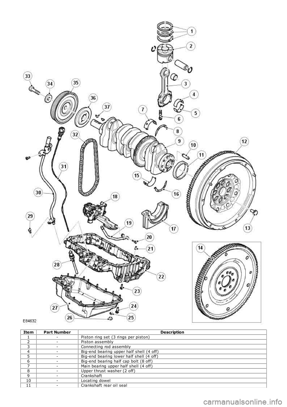
ItemPart NumberDescription
1-Pi s ton ring s et (3 ri ngs per pi st on)2-Pi s ton as s embly
3-Connect ing rod as s embly
4-Bi g-end beari ng upper half s hell (4 off)5-Bi g-end beari ng lower half s hell (4 off)
6-Bi g-end beari ng half cap bol t (8 off)
7-Mai n beari ng upper half s hell (4 off)8-Upper t hrus t washer (2 off)
9-Cranks haft
10-Locati ng dowel11-Cranks haft rear oi l seal
Page 770 of 3229
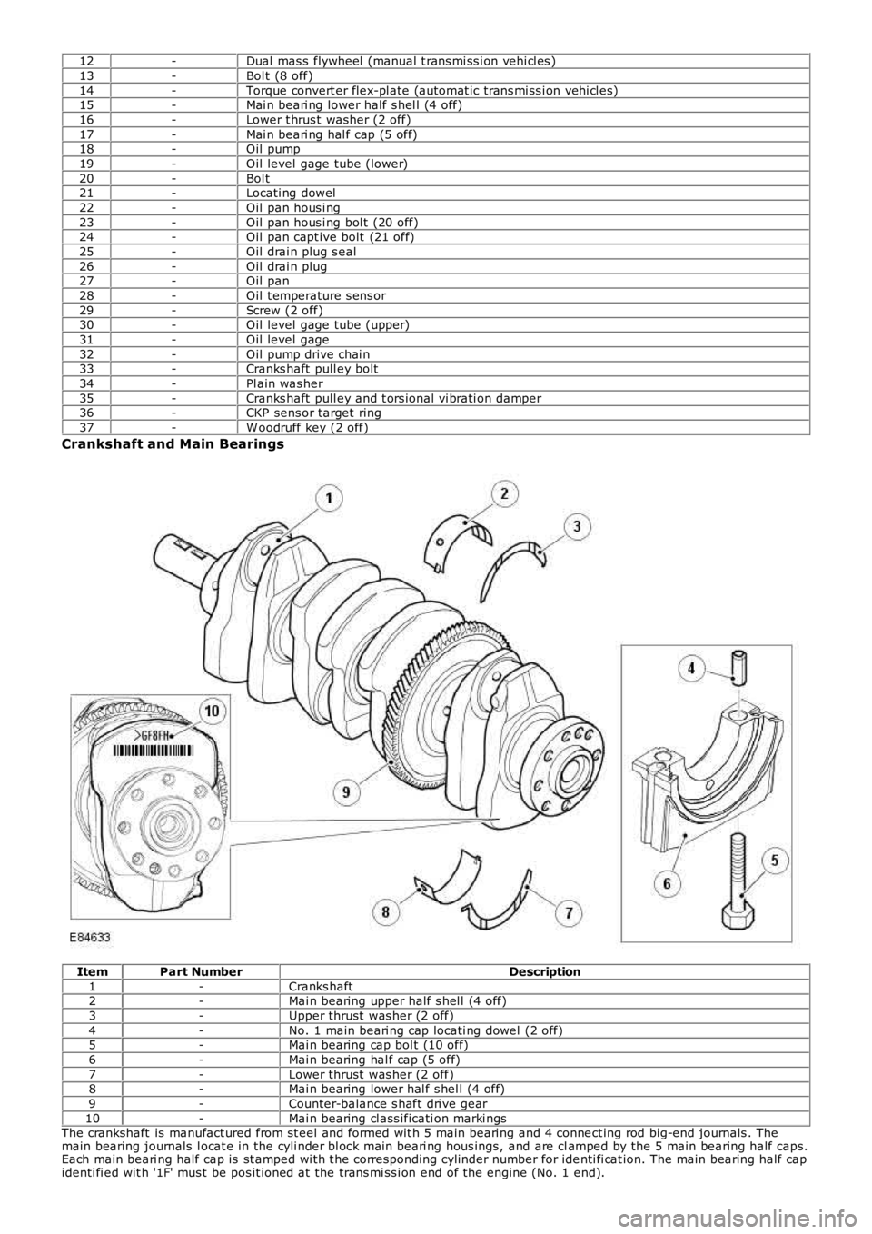
12-Dual mas s flywheel (manual t rans mi ss i on vehi cl es )
13-Bol t (8 off)
14-Torque convert er flex-pl ate (automat ic trans mi ss i on vehi cl es)15-Mai n beari ng lower half s hel l (4 off)
16-Lower t hrus t washer (2 off)
17-Mai n beari ng hal f cap (5 off)18-Oil pump
19-Oil level gage tube (lower)
20-Bol t21-Locati ng dowel
22-Oil pan hous i ng
23-Oil pan hous i ng bol t (20 off)24-Oil pan capt ive bolt (21 off)
25-Oil drai n plug s eal
26-Oil drai n plug27-Oil pan
28-Oil t emperature s ens or
29-Screw (2 off)30-Oil level gage tube (upper)
31-Oil level gage
32-Oil pump drive chai n33-Cranks haft pull ey bolt
34-Pl ain was her
35-Cranks haft pull ey and t ors ional vi brati on damper36-CKP sens or target ring
37-W oodruff key (2 off)
Crankshaft and Main Bearings
ItemPart NumberDescription
1-Cranks haft2-Mai n bearing upper half s hel l (4 off)
3-Upper thrust was her (2 off)
4-No. 1 main beari ng cap locati ng dowel (2 off)5-Mai n bearing cap bol t (10 off)
6-Mai n bearing hal f cap (5 off)
7-Lower thrust was her (2 off)8-Mai n bearing lower hal f s hel l (4 off)
9-Counter-balance s haft dri ve gear
10-Mai n bearing cl ass ificati on marki ngsThe crankshaft is manufact ured from st eel and formed wit h 5 main beari ng and 4 connect ing rod big-end journals . Themain bearing journals l ocat e in the cyli nder bl ock mai n beari ng hous ings , and are clamped by the 5 main bearing half caps.Each main beari ng half cap is st amped wi th t he corresponding cylinder number for identi fi cat ion. The main bearing half capidenti fi ed wit h '1F' mus t be pos it ioned at the trans mi ss i on end of the engine (No. 1 end).