LAND ROVER FRELANDER 2 2006 Repair Manual
Manufacturer: LAND ROVER, Model Year: 2006, Model line: FRELANDER 2, Model: LAND ROVER FRELANDER 2 2006Pages: 3229, PDF Size: 78.5 MB
Page 781 of 3229
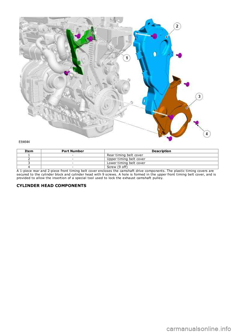
ItemPart NumberDescription
1-Rear ti ming belt cover2-Upper t iming belt cover
3-Lower t iming belt cover
4-Screw (9 off)A 1-piece rear and 2-pi ece front t iming belt cover enclos es the cams haft drive component s. The pl as t ic t iming covers ares ecured to the cyli nder block and cylinder head wit h 9 s crews . A hol e is formed in the upper front t iming belt cover, and isprovided t o all ow t he ins ert ion of a special t ool us ed to lock t he exhaus t cams haft pull ey.
CYLINDER HEAD COMPONENTS
Page 782 of 3229
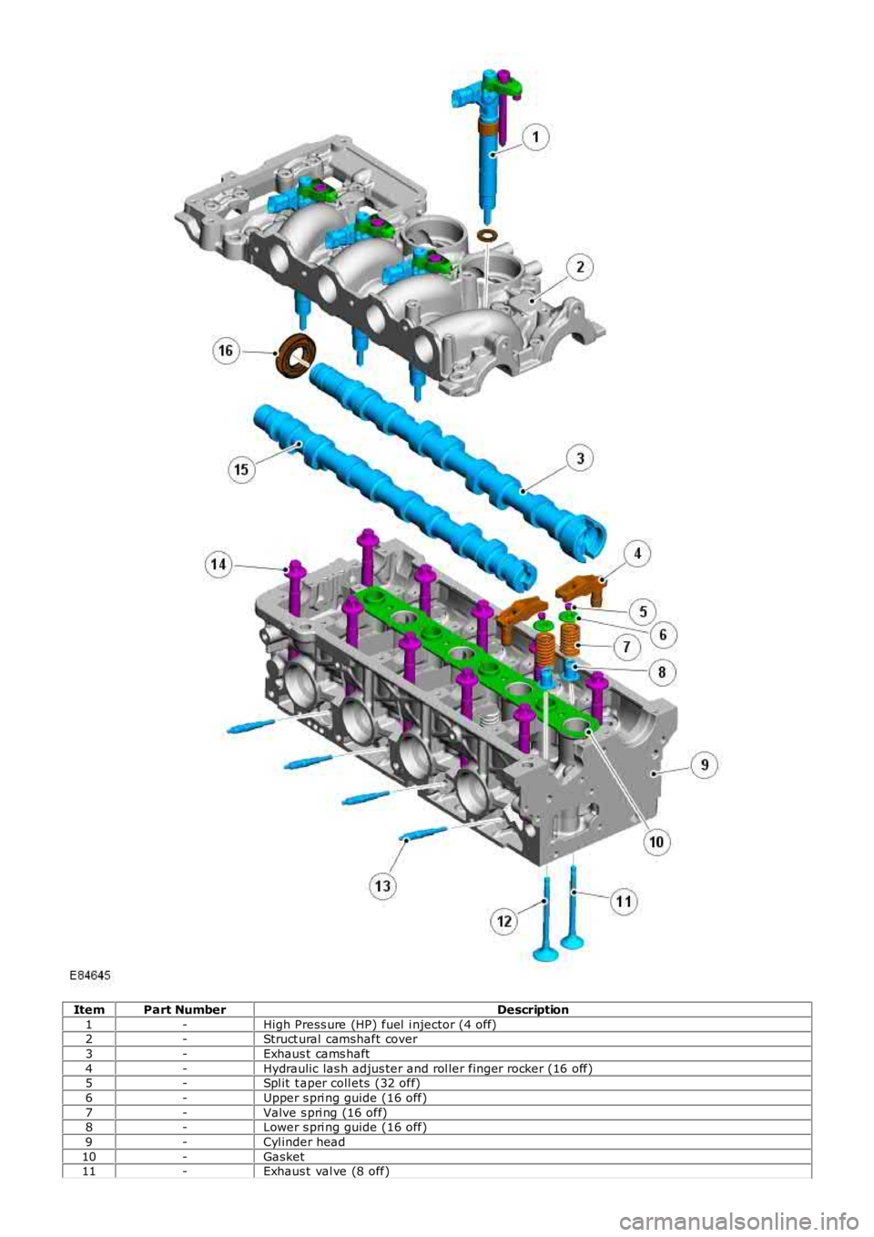
ItemPart NumberDescription
1-High Press ure (HP) fuel i njector (4 off)2-Struct ural camshaft cover
3-Exhaus t cams haft
4-Hydraulic las h adjus ter and rol ler finger rocker (16 off)5-Spl it t aper coll ets (32 off)
6-Upper s pri ng guide (16 off)
7-Valve s pri ng (16 off)8-Lower s pri ng guide (16 off)
9-Cyl inder head
10-Gasket11-Exhaus t val ve (8 off)
Page 783 of 3229
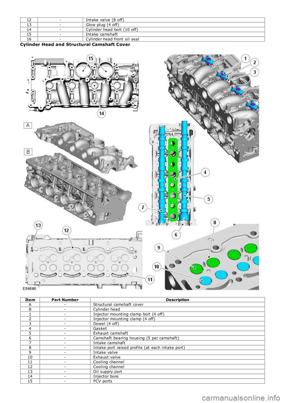
12-Int ake val ve (8 off)
13-Glow pl ug (4 off)
14-Cyl inder head bol t (10 off)15-Int ake cams haft
16-Cyl inder head front oi l seal
Cylinder Head and Structural Camshaft Cover
ItemPart NumberDescriptionA-St ructural cams haft cover
B-Cyli nder head
1-Injector mount ing clamp bol t (4 off)2-Injector mount ing clamp (4 off)
3-Dowel (4 off)
4-Gas ket5-Exhaus t cams haft
6-Cams haft beari ng hous i ng (5 per cams haft )
7-Intake cams haft8-Intake port rais ed profil e (at each i nt ake port )
9-Intake valve
10-Exhaus t valve11-Cooli ng channel
12-Cooli ng channel
13-Oi l s upply port14-Injector bore
15-PCV ports
Page 784 of 3229
The cyl inder head and st ructural cams haft cover are manufactured to form mat ing parts . The part s are mil led i n a si ngl eoperati on and accurat ely pos it ioned wi th 2 alignment s leeves. The 2 components mus t al ways be ins tall ed t oget her, andnot renewed as s eparate component s . The cyl inder head and cams haft cover are s eal ed to each ot her during manufact urewit h a gas ket and s ili cone bas ed s eal ant, and are s ecured wit h 27 bolt s . An oil s eal i nst all ed at the front of t he cyl inderhead provides s eal ing of t he exhaus t camshaft hous ing. The open port s at the rear of the cyli nder head are sealed wit ht he vacuum pump and hi gh-pres s ure fuel pump s eal ing rings .
Two ali gnment sl eeves correct ly l ocat e t he cyl inder head and gas ket to t he cylinder block. The cyli nder head is secured t ot he cyl inder bl ock wit h 10 deep-s eat ed bolt s .
• NOTE: The cyl inder head bol ts are not acces si ble wit h the st ruct ural cams haft cover i nst all ed.
• NOTE: The cyl inder head is not t o be reworked.
The cyl inder head is manufact ured from al uminum alloy, havi ng valve s eats and guides made of s i nt ered st eel. Thecyl inder head is precis ely machi ned and mil led t o i ncorporate t he 4 combus ti on chambers, cams haft l ower beari nghous i ngs , oil drill ings and cool ant gal leri es, and t he air i ntake, val ve ti ming and fuel sys t em component bores andhous i ngs .
The desi gn of the cyli nder head maximizes air flow and s wi rl i n the combus ti on chambers. The 2 int ake val ve seat s aremachined wit h rais ed profil es that act to promote swi rl of t he int ake ai r fl ow. Combined wit h t he acti on of the i ntakemanifold heli cal port , t he s wirl effect of the 2 int ake port profi les al lows t he air and i nject ed fuel t o complet el y mi x, andreach t he outer edge of the combus ti on chamber.
The s truct ural camshaft cover is manufact ured from alumi num all oy, and i s machined on t he upper s urface wit h t hecamshaft upper bearing hous ings . The cover is al so formed wi th 4 int ake ai r fi ll ing t racts , fuel i nject or bores and ori fi cesfor t he cyl inder head cover PCV components . The i nt ake air t racts join the i ntake air mani fold to the cyli nder head int akefi ll ing port s .
The cyl inder head al s o provides t he mounti ng locati ons for the foll owing:
Front engi ne mounti ngFront and rear engine l ifti ng eyesInt ake and exhaus t manifol dsEGR valve and coolerFuel fil ter s upport bracketThermal cont rol moduleVacuum pump and high-press ure fuel pump.
Cylinder Head G asket
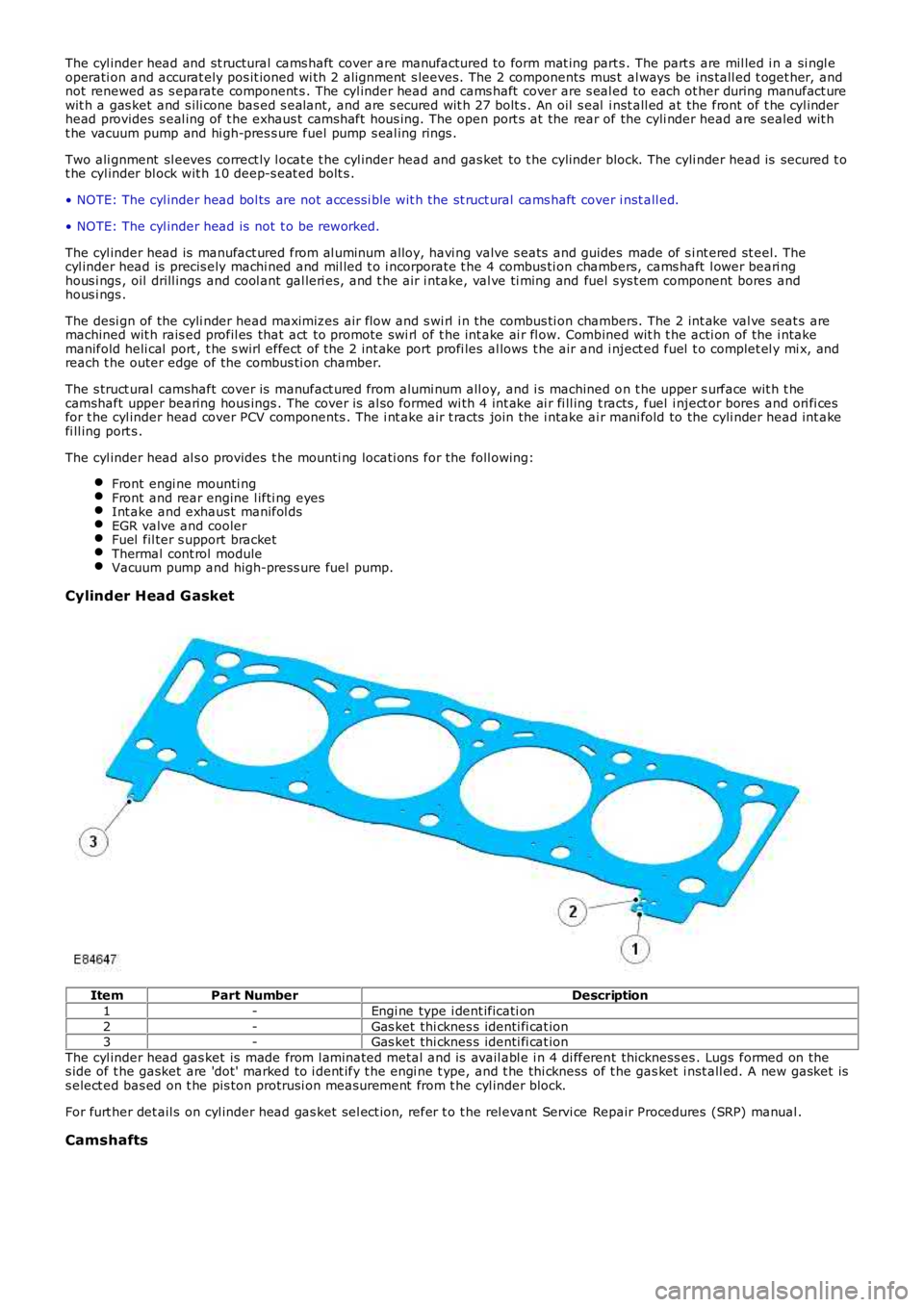
ItemPart NumberDescription
1-Engi ne type i dent ificati on
2-Gas ket thi cknes s identi fi cat ion3-Gas ket thi cknes s identi fi cat ion
The cyl inder head gas ket is made from l aminated metal and is avail abl e i n 4 di fferent thickness es . Lugs formed on thes ide of t he gasket are 'dot' marked to i dent ify t he engi ne t ype, and t he thi ckness of t he gas ket i nst all ed. A new gasket iss elect ed bas ed on t he pis ton protrusi on meas urement from t he cyl inder block.
For furt her det ail s on cyl inder head gas ket sel ect ion, refer t o t he rel evant Servi ce Repair Procedures (SRP) manual .
Camshafts
Page 785 of 3229
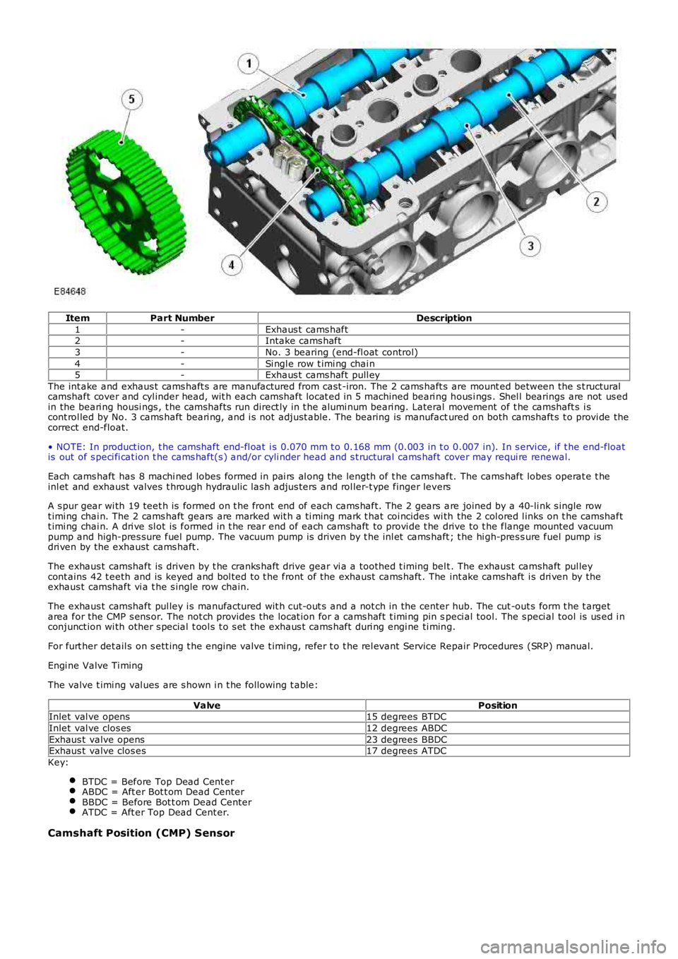
ItemPart NumberDescription
1-Exhaus t cams haft2-Intake cams haft
3-No. 3 bearing (end-fl oat control)
4-Si ngl e row t imi ng chai n5-Exhaus t cams haft pull ey
The int ake and exhaus t cams haft s are manufactured from cast -iron. The 2 cams haft s are mount ed between the s t ructuralcamshaft cover and cyl inder head, wit h each camshaft locat ed i n 5 machined beari ng hous i ngs . Shel l bearings are not us edin the beari ng housi ngs , t he camshafts run direct ly in t he alumi num beari ng. Lateral movement of t he camshaft s i scont rol led by No. 3 cams haft beari ng, and i s not adjust able. The bearing is manufactured on both camshaft s t o provi de thecorrect end-float.
• NOTE: In product ion, t he camshaft end-fl oat i s 0.070 mm t o 0.168 mm (0.003 in t o 0.007 in). In s ervi ce, if t he end-floatis out of s peci fi cat ion t he cams haft(s ) and/or cyli nder head and s t ructural cams haft cover may requi re renewal.
Each cams haft has 8 machi ned lobes formed in pai rs al ong the length of t he cams haft. The cams haft lobes operat e t heinl et and exhaust valves t hrough hydraulic las h adjus ters and rol ler-t ype finger levers
A s pur gear wi th 19 teet h is formed on t he front end of each cams haft. The 2 gears are joined by a 40-li nk s ingle rowt imi ng chai n. The 2 cams haft gears are marked wit h a ti ming mark t hat coi ncides wi th the 2 col ored l inks on t he camshaftt imi ng chai n. A dri ve sl ot is formed in t he rear end of each camshaft to provi de t he drive to t he flange mounted vacuumpump and high-pres sure fuel pump. The vacuum pump is driven by t he inl et cams haft ; the hi gh-pres s ure fuel pump isdri ven by the exhaust cams haft .
The exhaus t camshaft is driven by t he cranks haft drive gear vi a a toothed t iming belt . The exhaus t camshaft pul leycont ains 42 t eeth and is keyed and bol ted to t he front of the exhaust cams haft . The int ake cams haft i s dri ven by theexhaus t camshaft vi a t he s ingle row chain.
The exhaus t camshaft pul ley i s manufactured wit h cut-out s and a not ch in the center hub. The cut -out s form t he t argetarea for the CMP s ens or. The not ch provides the locat ion for a cams haft t imi ng pin speci al tool. The s peci al tool is us ed i nconjunct ion wi th other s pecial t ool s t o s et the exhaus t cams haft duri ng engi ne ti ming.
For furt her det ail s on s ett ing t he engine valve t imi ng, refer t o t he rel evant Service Repair Procedures (SRP) manual.
Engi ne Valve Ti ming
The valve t imi ng val ues are s hown i n t he fol lowing t able:
ValvePositionInlet val ve opens15 degrees BTDC
Inlet val ve clos es12 degrees ABDC
Exhaus t valve opens23 degrees BBDCExhaus t valve clos es17 degrees ATDC
Key:
BTDC = Before Top Dead Cent erABDC = Aft er Bot t om Dead CenterBBDC = Before Bot t om Dead CenterATDC = Aft er Top Dead Cent er.
Camshaft Position (CMP) Sensor
Page 786 of 3229
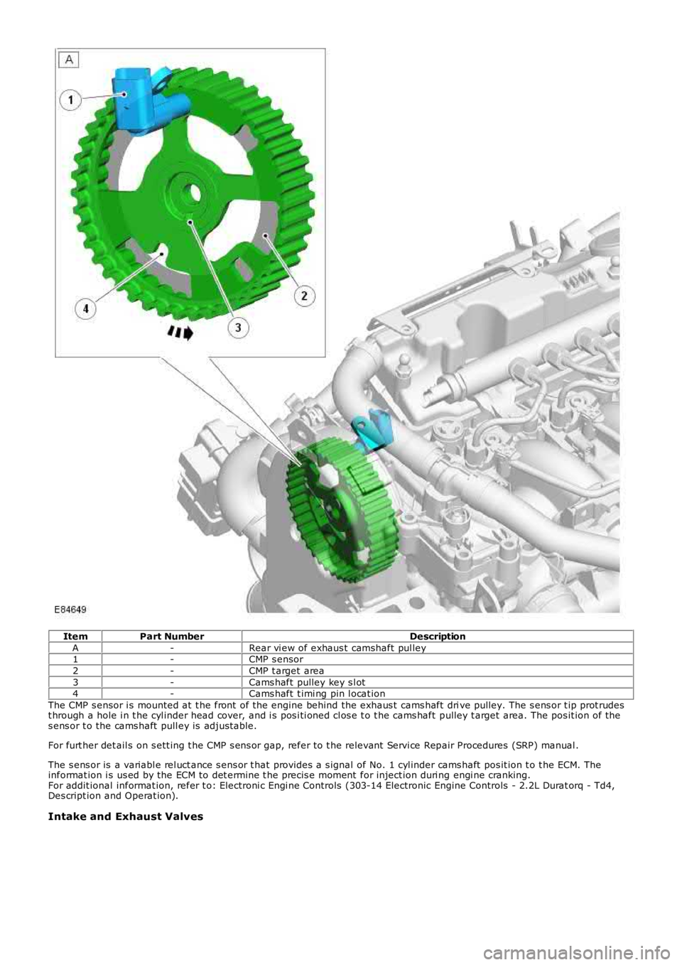
ItemPart NumberDescription
A-Rear vi ew of exhaus t camshaft pul ley1-CMP s ensor
2-CMP t arget area
3-Cams haft pulley key s l ot4-Cams haft t imi ng pin l ocat ion
The CMP s ensor i s mounted at t he front of the engine behind the exhaus t cams haft drive pulley. The s ens or t ip prot rudest hrough a hole i n t he cyl inder head cover, and i s pos i ti oned cl os e t o t he cams haft pulley t arget area. The pos it ion of t hes ens or t o the cams haft pull ey is adjust able.
For furt her det ail s on s ett ing t he CMP s ens or gap, refer to t he relevant Servi ce Repair Procedures (SRP) manual .
The s ens or is a variabl e rel uct ance s ens or t hat provides a s ignal of No. 1 cyl inder cams haft pos it ion t o t he ECM. Theinformat ion i s us ed by the ECM to det ermine t he precis e moment for inject ion duri ng engi ne cranking.For addit ional informat ion, refer t o: Electroni c Engi ne Controls (303-14 Electronic Engine Controls - 2.2L Durat orq - Td4,Des cript ion and Operat ion).
Intake and Exhaust Valves
Page 787 of 3229
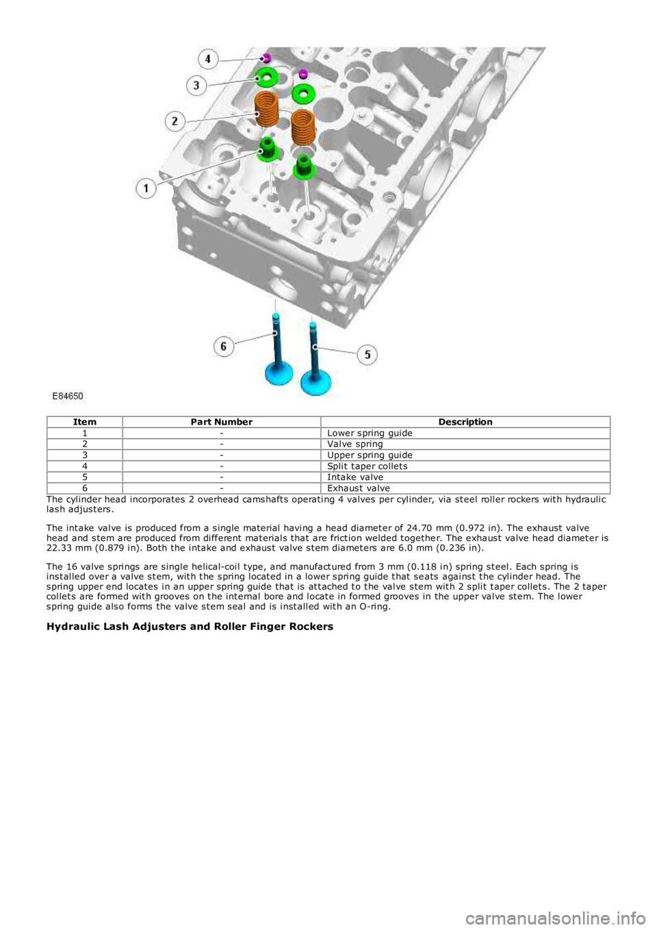
ItemPart NumberDescription
1-Lower s pring gui de2-Val ve spring
3-Upper s pring gui de
4-Spli t t aper collet s5-Intake valve
6-Exhaus t valve
The cyl inder head incorporates 2 overhead cams haft s operati ng 4 valves per cyl inder, via st eel roll er rockers wit h hydrauli clas h adjus t ers .
The int ake val ve is produced from a s ingle material havi ng a head diamet er of 24.70 mm (0.972 in). The exhaust valvehead and s tem are produced from di fferent mat erial s that are frict ion welded t ogether. The exhaus t valve head diamet er is22.33 mm (0.879 i n). Both the i ntake and exhaus t valve s t em diamet ers are 6.0 mm (0.236 in).
The 16 valve s pri ngs are s ingl e helical-coi l type, and manufact ured from 3 mm (0.118 i n) spring s t eel . Each s pring i sins t al led over a valve s t em, wit h t he s pring l ocat ed in a lower s pri ng guide t hat s eats agai ns t t he cyl inder head. Thes pring upper end locates i n an upper spring guide that is at t ached t o t he val ve s tem wit h 2 s pli t t aper collet s . The 2 tapercol let s are formed wit h grooves on t he int ernal bore and l ocat e in formed grooves in the upper val ve st em. The l owers pring gui de als o forms the valve s t em s eal and is i nst all ed wit h an O-ri ng.
Hydraulic Lash Adjusters and Roller Finger Rockers
Page 788 of 3229
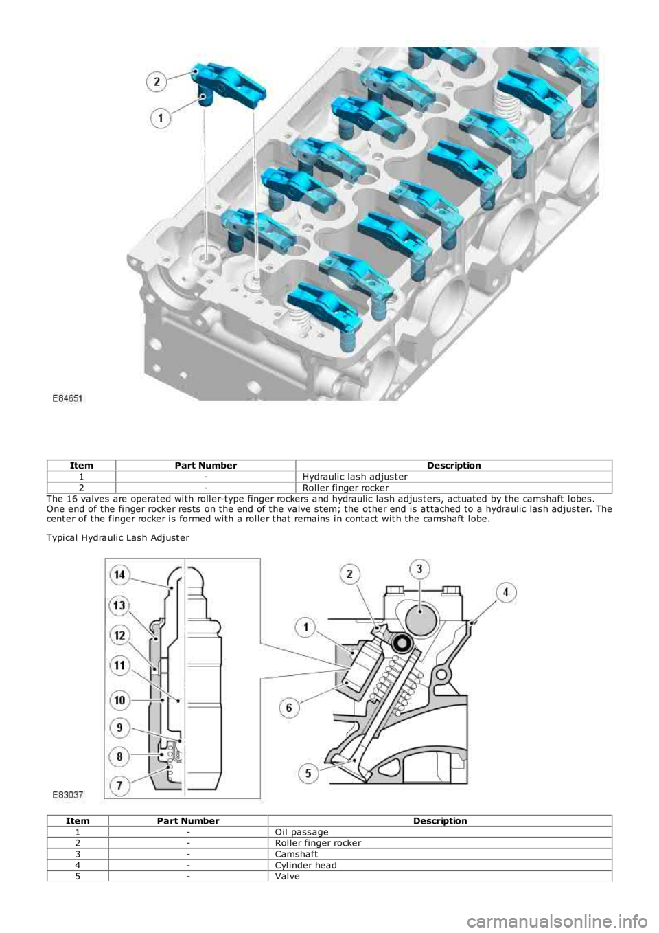
ItemPart NumberDescription
1-Hydrauli c las h adjus t er
2-Roll er fi nger rockerThe 16 valves are operat ed wi th roll er-type finger rockers and hydraulic las h adjus ters, actuat ed by the cams haft l obes .One end of t he fi nger rocker res ts on the end of t he valve s t em; the ot her end is attached to a hydraulic las h adjus ter. Thecent er of the finger rocker i s formed wi th a rol ler t hat remains i n cont act wit h the cams haft l obe.
Typi cal Hydrauli c Lash Adjust er
ItemPart NumberDescription
1-Oil pass age2-Rol ler finger rocker
3-Camshaft
4-Cyl inder head5-Val ve
Page 789 of 3229
6-Hydraul ic l ash adjust er
7-Pl unger s pri ng
8-High-pres s ure chamber9-Bal l val ve
10-Pl unger
11-Res ervoir chamber12-Oil pass age
13-Hydraul ic l ash adjust er body
14-Pl unger capMovement of t he cams haft lobe pres s es down on t he fi nger rocker rol ler, and cons equentl y, t he hydrauli c las h adjus ter andvalve mechani sm are forced down together. The res pecti ve valve is forced down against valve s pri ng pres sure, and thehydraulic pl unger i s als o forced int o an oil chamber in t he cyl inder head. This t ype of val ve act uati on mini mizes fri ct ionbetween t he valve operat ing component s, and al so eliminates t he requi rement for manual adjust ment .
The body of the hydrauli c las h adjus t er contai ns a plunger, and 2 chambers for oil feed and press uri zed oil. Thepres s urized oi l i s s uppl ied t o t he las h adjus t er vi a t he cyl inder head oi l gal lery, and t hrough a hole in t he s ide of t he las hadjus ter body. The oi l pas s es int o a feed chamber wi thin the l ash adjus ter, and t hen t hrough to a s eparate press urechamber via a one-way ball valve.
Oil flow from t he pres s ure chamber is det ermi ned by the clearance bet ween the l ash adjust er outer body and the centerplunger. Oi l es capes up the s i de of the pl unger each ti me t he las h adjus t er i s operated. The downward press ure on t heplunger forces a corres ponding amount of oil i n the las h adjus ter body to be dis placed.
As t he camshaft lobe rot ates furt her, downward press ure on the cams haft and finger rocker i s removed. The las h adjus t erplunger is forced up by t he oil pres s ure contai ned in t he pres s ure chamber. The press ure i s not s uffi cient to affect valveoperati on, but i s s uffi cient to el iminate the clearance between the finger rocker and t op of the val ve st em.
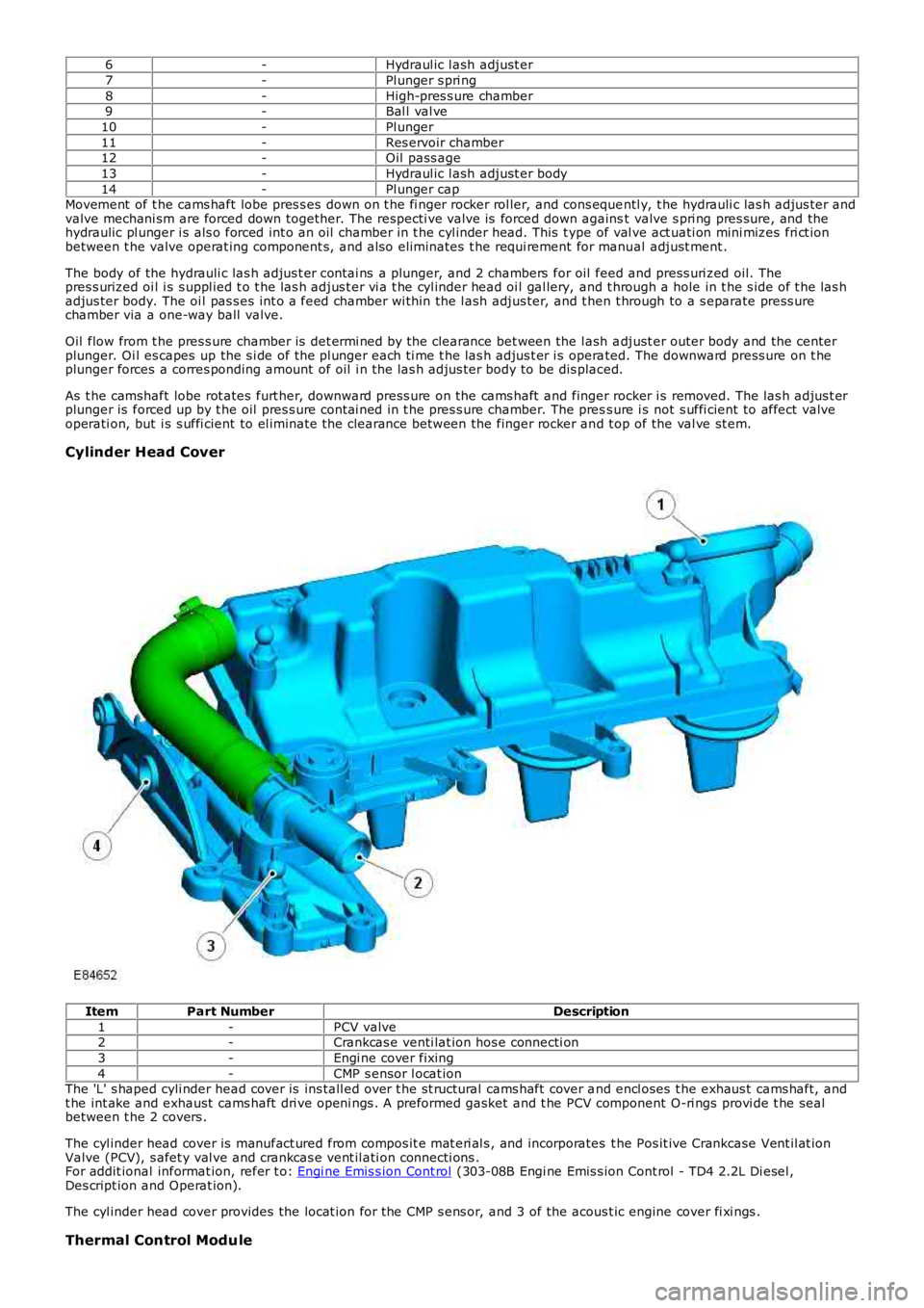
Cylinder Head Cover
ItemPart NumberDescription
1-PCV valve2-Crankcas e venti lat ion hos e connecti on
3-Engi ne cover fixing
4-CMP s ensor l ocat ionThe 'L' s haped cyli nder head cover is ins tall ed over t he s t ructural cams haft cover and encl oses t he exhaus t cams haft, andt he int ake and exhaust cams haft dri ve openi ngs . A preformed gasket and t he PCV component O-ri ngs provi de t he sealbetween t he 2 covers .
The cyl inder head cover is manufact ured from compos it e mat eri al s , and incorporates the Pos it ive Crankcase Vent il at ionValve (PCV), s afet y val ve and crankcas e vent il ati on connecti ons .For addit ional informat ion, refer t o: Engi ne Emis s ion Cont rol (303-08B Engi ne Emis s ion Cont rol - TD4 2.2L Di esel ,Des cript ion and Operat ion).
The cyl inder head cover provides the locat ion for the CMP s ens or, and 3 of the acoust ic engine cover fi xi ngs .
Thermal Control Module
Page 790 of 3229
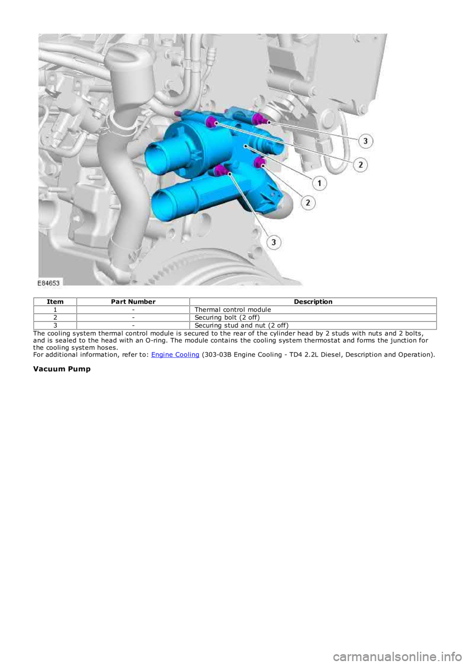
ItemPart NumberDescription
1-Thermal control modul e2-Securi ng bol t (2 off)
3-Securi ng s tud and nut (2 off)
The cool ing s ys tem thermal control modul e i s s ecured to t he rear of t he cyl inder head by 2 s tuds wi th nut s and 2 bol ts ,and is sealed to the head wi th an O-ring. The module contai ns the cooli ng s ys t em t hermos tat and forms the junct ion fort he cooli ng s yst em hos es.For addit ional informat ion, refer t o: Engi ne Cooling (303-03B Engine Cooli ng - TD4 2.2L Dies el , Descripti on and Operat ion).
Vacuum Pump