LAND ROVER FRELANDER 2 2006 Repair Manual
Manufacturer: LAND ROVER, Model Year: 2006, Model line: FRELANDER 2, Model: LAND ROVER FRELANDER 2 2006Pages: 3229, PDF Size: 78.5 MB
Page 771 of 3229
Lateral movement of the cranks haft is res trict ed by 4 half-round thrus t was hers , located on bot h s ides of No. 2 mai nbearing. Lubricati on grooves are formed on t he thrus t was hers and mus t face toward the main beari ng. The cranks haftend-float mus t be bet ween 0.07 mm (0.003 in) and 0.32 mm (0.013 i n).
Each main beari ng housi ng and half cap cont ains an upper and lower bearing half s hell manufactured from al uminum/ti n.The upper half s hell s are formed wit h a dril li ng and annular groove t o t rans fer press uri zed oi l from t he main bearing,t hrough cranks haft drill ings t o t he connecti ng rod bi g-end bearings .
The main bearing half caps and t he upper and l ower beari ng half s hel ls are formed with a l ug. The l ug allows correctali gnment of t he bearing and cap, and prevent s radi al movement of t he bearing.
To mai nt ain the correct cranks haft mai n bearing cl earance, the main beari ng half s hells are avail abl e in varying t hicknes s .The upper mai n beari ng hal f s hel l is only avail abl e i n 1 s ize; t he lower mai n bearing hal f shell i s avai lable in 5 si zes . Bot ht he upper and lower mai n bearing hal f shel ls are col or coded for i dent ificati on. To det ermi ne t he correct s ize of bearing hal fs hel l, clas s ificat ion markings on t he cranks haft front face and on t he cyl inder bl ock front face are us ed in conjunct ion wi tha beari ng s ize chart .
For furt her det ail s on main bearing half s hell i ns t allat ion, refer to the relevant Servi ce Repai r Procedures (SRP).
A drive gear is formed as a 's hri nk-fit ' on No. 3 cranks haft web, located bet ween No. 2 mai n bearing journal and No. 2connecti ng rod bi g-end journal . The dri ve gear i s s ingle hel ical cut and provides t he dri ve to the counter-balance s haftgears . An 18 t eet h s pur gear i s located on the front of the cranks haft , behi nd the front cranks haft s eal ing pl at e. The s purgear provi des the drive t o t he oil pump as s embly via a s ingle row chain, and i s locked to the cranks haft wit h a woodruffkey.
A t oothed gear mount ed t o t he front of t he cranks haft provides t he dri ve for t he cams haft t iming belt . The dri ve gearcont ains 21 t eeth and is keyed to the cranks haft wit h a woodruff key.
Crankshaft Oil Seals
Page 772 of 3229
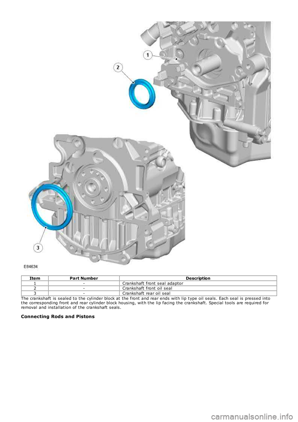
ItemPart NumberDescription
1-Cranks haft front s eal adaptor2-Cranks haft front oil s eal
3-Cranks haft rear oi l s eal
The crankshaft is s ealed t o t he cyl inder bl ock at the front and rear ends wit h l ip type oil s eals . Each s eal is press ed i ntot he corres pondi ng front and rear cyli nder bl ock hous ing, wit h t he li p facing the cranks haft. Special tools are requi red forremoval and ins tal lat ion of t he cranks haft s eals .
Connecting Rods and Pistons
Page 773 of 3229
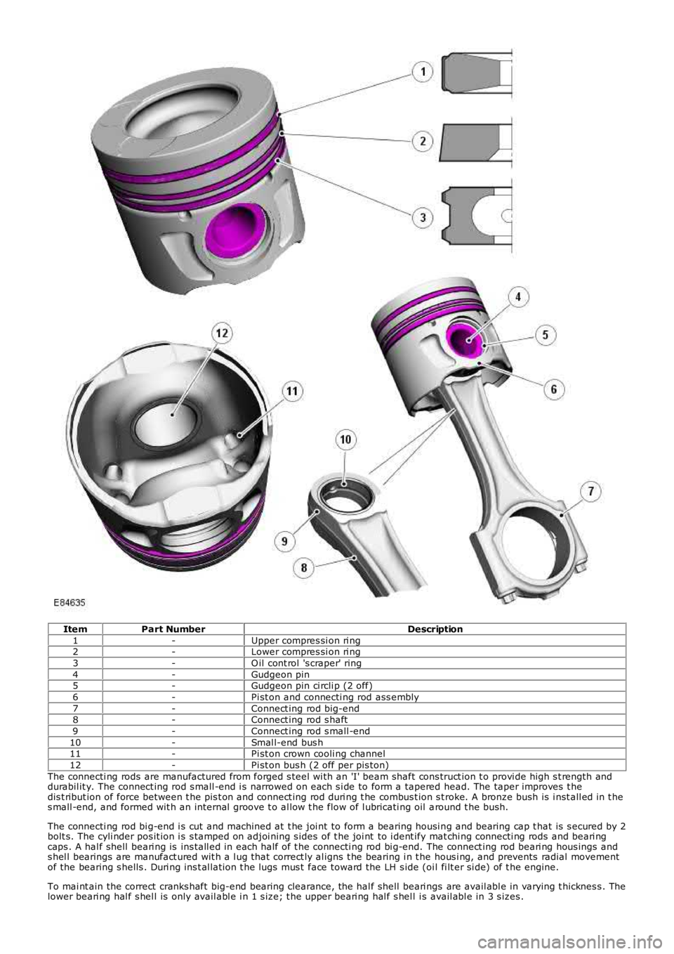
ItemPart NumberDescription
1-Upper compres si on ri ng2-Lower compres si on ri ng
3-O il cont rol 's craper' ring
4-Gudgeon pin5-Gudgeon pin ci rcli p (2 off)
6-Pi st on and connecti ng rod ass embly
7-Connect ing rod big-end8-Connect ing rod s haft
9-Connect ing rod s mall -end
10-Smal l-end bus h11-Pi st on crown cooli ng channel
12-Pi st on bus h (2 off per pis ton)
The connecti ng rods are manufactured from forged s teel wi th an 'I' beam shaft cons truct ion t o provi de high s t rength anddurabil it y. The connect ing rod s mall -end i s narrowed on each s i de to form a tapered head. The taper improves t hedis t ribut ion of force between t he pis t on and connect ing rod duri ng t he combus t ion s troke. A bronze bush is i nst all ed in t hes mall -end, and formed wit h an internal groove t o al low t he flow of l ubricati ng oil around t he bush.
The connecti ng rod bi g-end i s cut and machined at t he joi nt to form a bearing housi ng and bearing cap t hat is s ecured by 2bolt s. The cyli nder pos it ion i s s tamped on adjoi ning s ides of t he joi nt to i dent ify mat chi ng connecti ng rods and beari ngcaps . A hal f shell beari ng is ins tall ed in each half of t he connecti ng rod bi g-end. The connect ing rod beari ng hous ings ands hel l bearings are manufact ured wit h a l ug that correct ly al igns t he bearing i n t he hous i ng, and prevents radial movementof the bearing s hells . Duri ng ins t al lat ion t he lugs mus t face toward the LH s ide (oil fi lt er si de) of t he engine.
To mai nt ain the correct cranks haft big-end bearing clearance, the hal f shell beari ngs are avail abl e in varying t hicknes s . Thelower beari ng hal f s hel l is only avail abl e i n 1 s ize; t he upper beari ng hal f s hel l is avail abl e in 3 s izes .
Page 774 of 3229
For furt her det ail s on connecti ng rod bi g-end beari ng ins tal lati on, refer t o t he relevant Service Repair Procedures (SRP).
The pis t ons are manufactured from al uminum alloy and are i ns t alled wit h 2 compres s ion rings , and an oil cont rol ring wi tha s piral spring. A s teel ins ert i s i ns t alled in t he pis t on upper ring groove t o provi de reinforcement. The pis t on crown i s at oroidal des i gn that forms a pronounced bowl in t he center of the pi s ton head. Recesses are als o formed in t he pis t oncrown t o provi de cl earance for t he 4 valve heads. This des ign of combus ti on chamber promot es high l evel s of swirl andt urbulence required for complete combus t ion of t he air/fuel mi xture, and al so improves t he engine emi ss i ons .
The 3 pi st on rings mus t be ins t al led wi th the ring gaps s paced at 120° (wit h permis sible tolerance of 15° t o 20°) to eachother, around the pi st on. The 2 upper compres s ion rings are s tamped wi th 't op' t o aid ins tall ati on. The gap of t he doubl ebevel ed oil cont rol ring mus t als o be oppos it e t he s pi ral s pri ng joint .
The ful l ski rt pis t on is coated wit h a graphi te bas ed s ubst ance to reduce fri cti on wit h t he cyl inder bore. The graphi te bas edcoat ing i s es pecial ly i mport ant during t he engine runni ng in period and s t art-up. The pis ton al so incorporat es 2 oil coolingchannels t hat are formed on the unders i de of the pi st on head.
Two bus hed hol es are formed at oppos it e s ides of t he pis ton s kirt for i nst all at ion of a full y floati ng gudgeon pin. Thegudgeon pi n pass es t hrough the pi s ton bus hed hol es and connecti ng rod s mal l-end, and i s ret ained at each end wit h acircl ip. The pis ton, gudgeon pi n and connecti ng rod smal l-end are s uppli ed wit h oil from an oil s pray jet, l ocat ed bel oweach cyli nder bore.
Duri ng ins tal lat ion of t he pis tons , the s t amped direct ion arrow and 'DIST' on each pis ton crown mus t face t oward t he frontof the engine (acces s ory drive end).
For furt her det ail s on pis t on and pis ton ring ins tall ati on, refer t o the relevant Service Repai r Procedures (SRP) manual.
Oil Pan Housing and Oil Separator
Page 775 of 3229
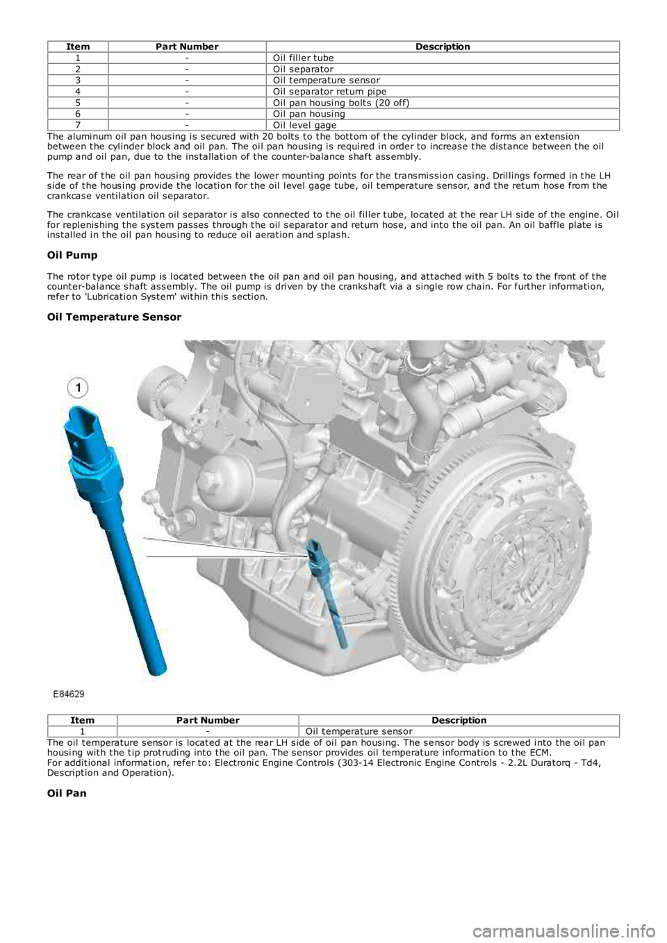
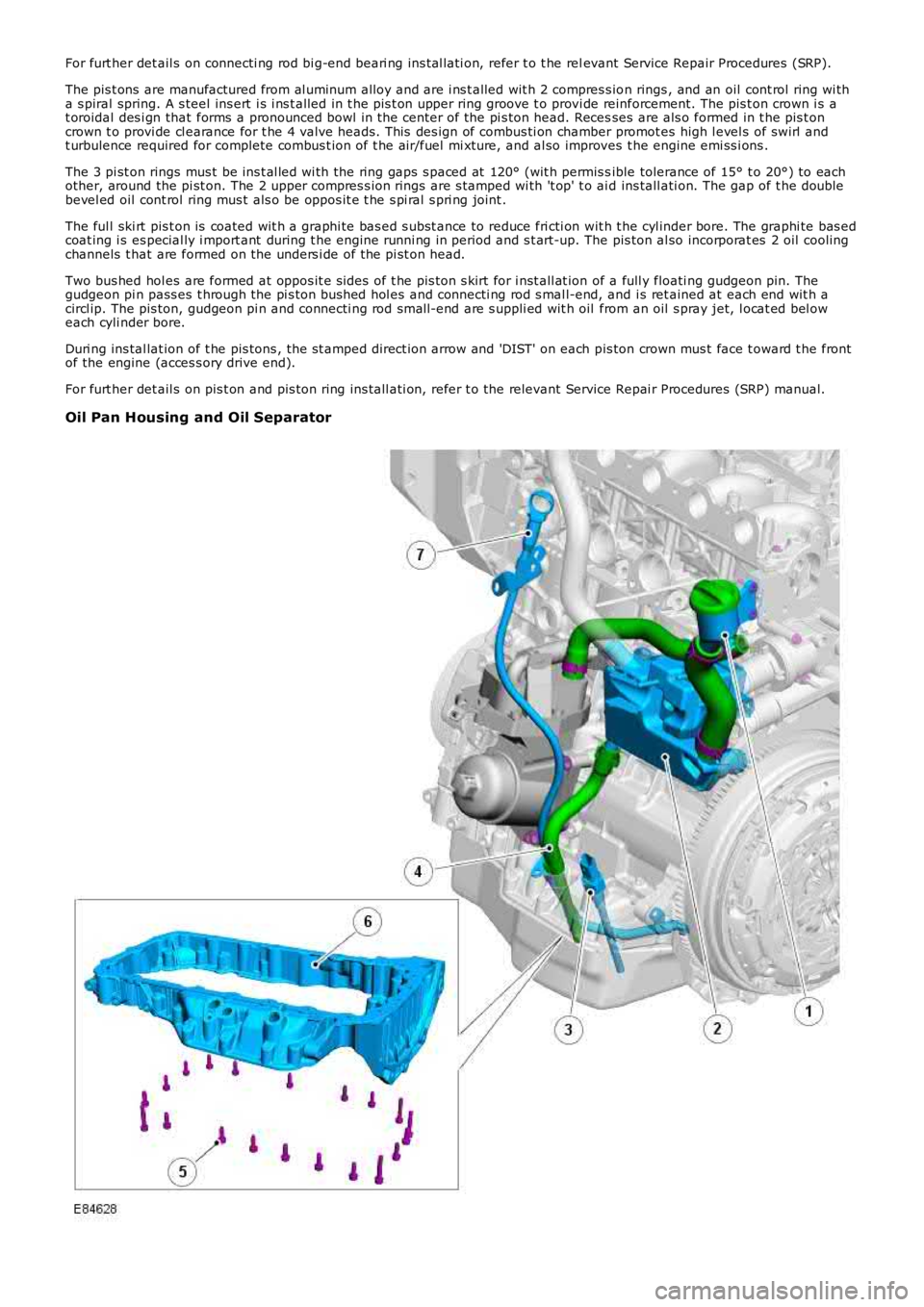
ItemPart NumberDescription
1-Oil fill er tube
2-Oil s eparator3-Oil t emperature s ens or
4-Oil s eparator ret urn pi pe
5-Oil pan housi ng bolt s (20 off)6-Oil pan housi ng
7-Oil level gage
The alumi num oil pan hous ing i s s ecured wit h 20 bolt s t o t he bot t om of t he cyl inder bl ock, and forms an ext ens ionbetween t he cyl inder block and oil pan. The oi l pan hous ing i s requi red i n order t o increas e t he dis tance between t he oilpump and oil pan, due to the ins tall ati on of the counter-balance s haft ass embly.
The rear of t he oil pan hous i ng provides t he lower mounti ng poi nts for the trans mi s si on cas i ng. Dril lings formed in t he LHs ide of t he hous i ng provide t he locati on for t he oil l evel gage tube, oil t emperature s ens or, and t he ret urn hos e from t hecrankcas e venti lati on oil s eparator.
The crankcas e venti lati on oil s eparator i s als o connected to t he oil fil ler t ube, located at t he rear LH si de of the engine. Oi lfor repl enis hing t he s ys t em pas ses through t he oil s eparator and return hos e, and int o t he oil pan. An oil baffle pl ate i sins t al led i n t he oil pan housi ng to reduce oil aerat ion and s plas h.
Oil Pump
The rot or type oil pump is l ocat ed bet ween t he oil pan and oil pan housi ng, and at t ached wi th 5 bol ts to the front of t hecount er-bal ance s haft as s embly. The oil pump i s dri ven by the cranks haft via a s ingle row chain. For furt her informati on,refer to 'Lubricati on Sys t em' wit hin t his s ecti on.
Oil Temperature Sensor
ItemPart NumberDescription1-Oil t emperature s ens or
The oil t emperature s ens or is locat ed at t he rear LH s ide of oi l pan hous ing. The s ens or body is s crewed i nto the oi l panhous i ng wit h t he t ip prot rudi ng int o t he oil pan. The s ens or provi des oi l temperat ure informati on t o t he ECM.For addit ional informat ion, refer t o: Electroni c Engi ne Controls (303-14 Electronic Engine Controls - 2.2L Durat orq - Td4,Des cript ion and Operat ion).
Oil Pan
Page 776 of 3229
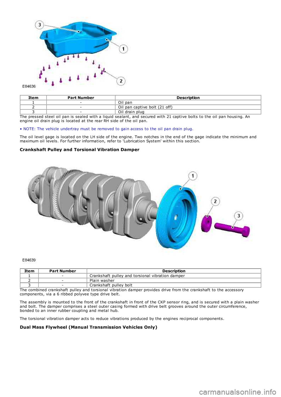
ItemPart NumberDescription
1-Oil pan2-Oil pan capti ve bol t (21 off)
3-Oil drai n plug
The pres s ed s teel oil pan is sealed wit h a l iquid sealant , and secured wi th 21 capt ive bolt s t o t he oil pan housi ng. Anengi ne oil drai n plug is l ocat ed at the rear RH s ide of t he oil pan.
• NOTE: The vehi cle undert ray mus t be removed to gai n acces s t o t he oil pan drain plug.
The oil l evel gage is l ocat ed on t he LH s ide of t he engi ne. Two not ches in t he end of t he gage indicate t he mi nimum andmaximum oil l evels . For further informat ion, refer t o 'Lubricat ion Sys t em' wit hi n t his s ect ion.
Crankshaft Pulley and Torsional Vibration Damper
ItemPart NumberDescription
1-Cranks haft pull ey and torsi onal vibrat ion damper
2-Plai n was her3-Cranks haft pull ey bol t
The combined crankshaft pul ley and t ors ional vi brat ion damper provides dri ve from t he crankshaft to the acces s orycomponents , via a 6 ribbed polyvee type drive belt .
The as sembl y is mount ed t o t he front of t he crankshaft in front of t he CKP s ens or ring, and i s s ecured wit h a pl ain was herand bolt . The damper compri ses a s teel out er cas i ng formed wit h drive belt grooves around t he outer circumference,bonded t o an inner rubber coupl ing and metal hub.
The t ors ional vi brati on damper act s to reduce vibrat ions produced by the engines reci procal component s .
Dual Mass Flywheel (Manual Transmission Vehicles Only)
Page 777 of 3229
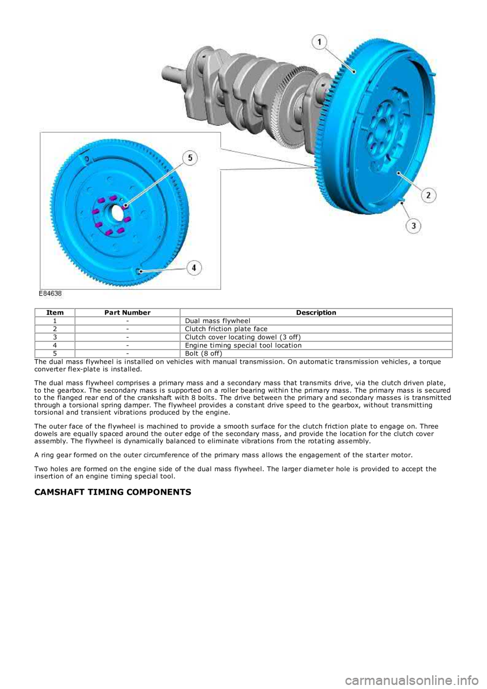
ItemPart NumberDescription
1-Dual mas s flywheel2-Clut ch fricti on plate face
3-Clut ch cover locat ing dowel (3 off)
4-Engi ne ti mi ng special t ool l ocati on5-Bolt (8 off)
The dual mas s flywheel is i nst all ed on vehi cl es wit h manual transmis si on. On automatic t rans mis s ion vehicles , a t orqueconvert er fl ex-plat e is ins tall ed.
The dual mas s flywheel compris es a primary mas s and a s econdary mass that t rans mit s dri ve, vi a the cl utch dri ven plate,t o the gearbox. The s econdary mas s i s s upported on a rol ler bearing wit hi n t he pri mary mass . The pri mary mas s is s ecuredt o the fl anged rear end of t he crankshaft wit h 8 bolt s . The drive bet ween the primary and s econdary mass es i s transmit tedt hrough a t ors ional spring damper. The flywheel provi des a cons t ant drive s peed to the gearbox, wit hout trans mi tt ingt ors ional and t rans ient vibrat ions produced by t he engi ne.
The outer face of t he fl ywheel i s machi ned to provide a smoot h s urface for the cl utch fri ct ion pl at e t o engage on. Threedowels are equal ly s paced around the out er edge of t he s econdary mas s , and provide the l ocati on for t he clut ch coveras sembl y. The flywheel is dynamically bal anced t o eli mi nat e vibrat ions from t he rot at ing as s embly.
A ring gear formed on t he outer circumference of the primary mas s al lows t he engagement of the s t art er motor.
Two holes are formed on t he engine s ide of t he dual mass fl ywheel. The l arger diameter hole is provi ded to accept theins ert ion of an engine ti ming s peci al tool.
CAMSHAFT TIMING COMPONENTS
Page 778 of 3229
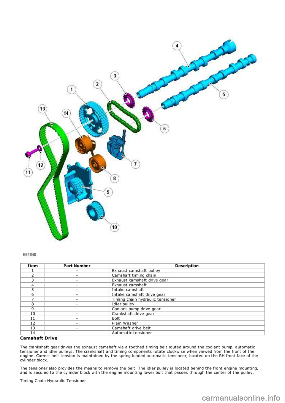
ItemPart NumberDescription
1-Exhaus t camshaft pul ley2-Cams haft ti mi ng chain
3-Exhaus t camshaft drive gear
4-Exhaus t camshaft5-Int ake camshaft
6-Int ake camshaft drive gear
7-Timi ng chai n hydraulic tens ioner8-Idl er pul ley
9-Cool ant pump dri ve gear
10-Crankshaft drive gear11-Bolt
12-Plain W as her
13-Cams haft dri ve bel t14-Automat ic t ensi oner
Camshaft Drive
The crankshaft gear dri ves the exhaus t cams haft via a toot hed ti ming bel t routed around the coolant pump, aut omat ict ens ioner and idl er pull eys . The cranks haft and ti ming components rotat e clockwi s e when viewed from the front of t heengi ne. Correct belt t ens ion is mai ntained by the s pri ng loaded automat ic t ensi oner, located on t he RH front face of thecyl inder block.
The t ens ioner als o provi des t he means t o remove the belt . The idl er pul ley i s located behind t he front engi ne mounti ng,and is secured t o t he cyl inder block wit h t he engi ne mounti ng lower bolt t hat pas s es through the center of t he pul ley.
Timi ng Chain Hydraul ic Tensi oner
Page 779 of 3229
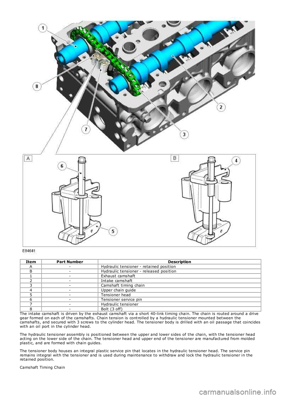
ItemPart NumberDescription
A-Hydraul ic t ensi oner - retai ned pos it ionB-Hydraul ic t ensi oner - releas ed pos i ti on
1-Exhaus t cams haft
2-Int ake cams haft3-Camshaft ti ming chain
4-Upper chain guide
5-Tens ioner head6-Tens ioner s ervice pin
7-Hydraul ic t ensi oner
8-Bol t (3 off)The int ake cams haft i s dri ven by the exhaust cams haft via a s hort 40-l ink t iming chai n. The chain is routed around a dri vegear formed on each of t he cams hafts . Chain t ensi on is cont roll ed by a hydrauli c t ens ioner mounted bet ween thecamshafts , and s ecured wit h 3 s crews to t he cylinder head. The t ensi oner body is dril led wi th an oil pas sage t hat coi ncideswit h an oi l port in the cyli nder head.
The hydraulic tens ioner as s embly i s posi ti oned bet ween t he upper and l ower s ides of t he chai n, wit h t he tens ioner headact ing on the lower si de of the chain. The t ens i oner head and upper end of t he tens ioner are manufact ured from moldedplas ti c, and are formed wi th chai n guides.
The t ens ioner body hous es an i nt egral plas ti c s ervice pin that locates i n t he hydraulic tens ioner head. The s ervice pinremai ns int egral wit h t he tens ioner and is us ed duri ng maint enance t o wi thdraw and lock the hydraul ic t ens i oner i n theret ained pos it ion.
Cams haft Timi ng Chain
Page 780 of 3229
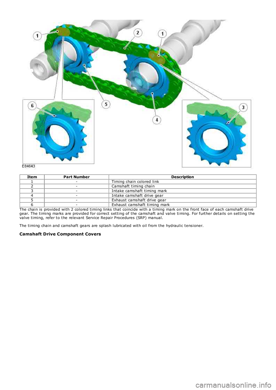
ItemPart NumberDescription
1-Timing chain colored li nk2-Cams haft t imi ng chai n
3-Intake cams haft ti ming mark
4-Intake cams haft dri ve gear5-Exhaus t cams haft dri ve gear
6-Exhaus t cams haft ti ming mark
The chai n is provided wi th 2 col ored t imi ng li nks that coinci de wi th a ti ming mark on the front face of each camshaft drivegear. The t imi ng marks are provided for correct s et t ing of t he cams haft and valve timing. For furt her det ails on s et t ing t hevalve t imi ng, refer t o t he relevant Service Repair Procedures (SRP) manual.
The t imi ng chai n and camshaft gears are spl as h l ubricat ed wit h oil from the hydraul ic t ens i oner.
Camshaft Drive Component Covers