LAND ROVER FRELANDER 2 2006 Repair Manual
Manufacturer: LAND ROVER, Model Year: 2006, Model line: FRELANDER 2, Model: LAND ROVER FRELANDER 2 2006Pages: 3229, PDF Size: 78.5 MB
Page 751 of 3229
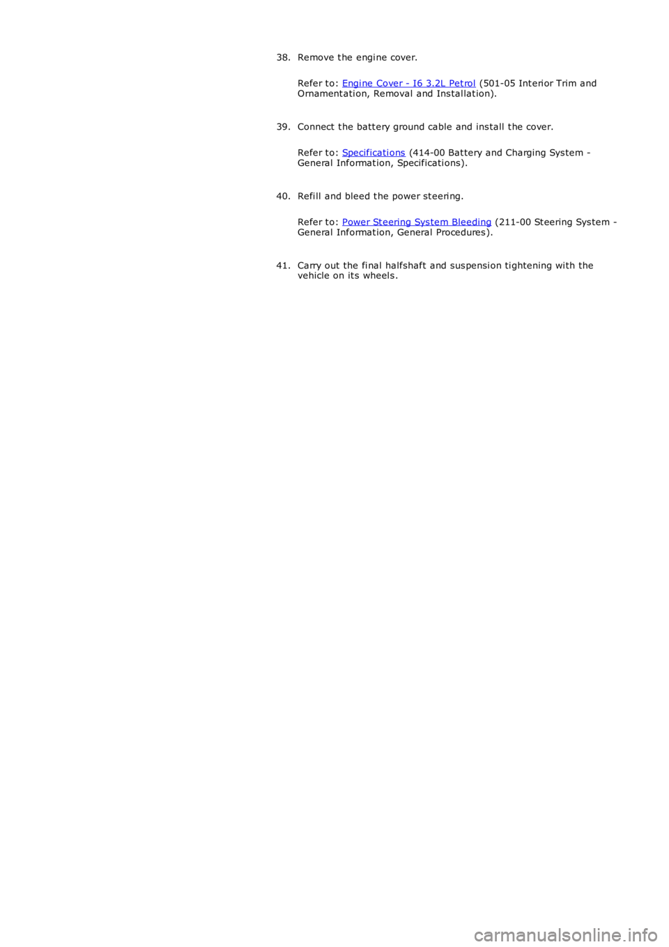
Remove t he engi ne cover.
Refer t o: Engi ne Cover - I6 3.2L Pet rol (501-05 Int eri or Trim andOrnament ati on, Removal and Ins tal lat ion).
38.
Connect t he batt ery ground cable and ins tall t he cover.
Refer t o: Specificati ons (414-00 Bat tery and Charging Sys tem -General Informat ion, Specificati ons).
39.
Refi ll and bleed t he power st eeri ng.
Refer t o: Power St eering Sys tem Bleeding (211-00 St eering Sys tem -General Informat ion, General Procedures ).
40.
Carry out the fi nal halfshaft and sus pensi on ti ghtening wi th thevehicle on it s wheel s .41.
Page 752 of 3229
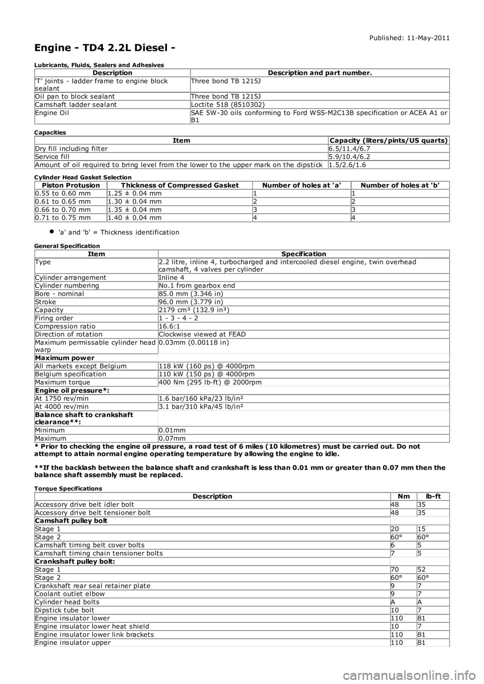
Publi s hed: 11-May-2011
Engine - TD4 2.2L Diesel -
Lubricants, Fluids, Sealers and AdhesivesDescriptionDescription and part number.
‘T’ joi nts - ladder frame to engi ne blocks ealantThree bond TB 1215J
Oi l pan to bl ock s ealantThree bond TB 1215J
Cams haft l adder s eal antLocti te 518 (8510302)
Engine Oi lSAE 5W -30 oils conforming to Ford W SS-M2C13B specificat ion or ACEA A1 orB1
C apacities
ItemCapacity (liters/pints/US quarts)
Dry fi ll i ncludi ng fi lt er6.5/11.4/6.7Service fil l5.9/10.4/6.2
Amount of oil required t o bri ng level from t he lower t o t he upper mark on t he dips tick1.5/2.6/1.6
C ylinder Head Gasket Selection
Piston ProtusionT hickness of Compressed GasketNumber of holes at ' a'Number of holes at 'b'0.55 to 0.60 mm1.25 ± 0.04 mm11
0.61 to 0.65 mm1.30 ± 0.04 mm22
0.66 to 0.70 mm1.35 ± 0.04 mm330.71 to 0.75 mm1.40 ± 0.04 mm44
'a' and 'b' = Thi ckness identi fi cat ion
General Specification
ItemSpecificationType2.2 l it re, i nl ine 4, t urbocharged and int ercool ed dies el engine, t win overheadcamshaft , 4 valves per cyl inder
Cyli nder arrangementInl ine 4Cyli nder numberi ngNo.1 from gearbox end
Bore - nominal85.0 mm (3.346 i n)
St roke96.0 mm (3.779 i n)Capaci ty2179 cm³ (132.9 in³)
Firing order1 - 3 - 4 - 2
Compres s ion rati o16.6:1Di recti on of rotat ionClockwi s e viewed at FEAD
Maximum permi s sable cyl inder headwarp0.03mm (0.00118 i n)
Maximum pow er
All markets except Bel gi um118 kW (160 ps ) @ 4000rpmBelgi um s peci fi cat ion110 kW (150 ps ) @ 4000rpm
Maximum t orque400 Nm (295 l b-ft ) @ 2000rpm
Engine oil pressure*:At 1750 rev/min1.6 bar/160 kPa/23 l b/i n²
At 4000 rev/min3.1 bar/310 kPa/45 l b/i n²
Balance shaft to crankshaftclearance**:
Mi ni mum0.01mm
Maximum0.07mm* Prior to checking the engine oil pressure, a road test of 6 miles (10 kilometres) must be carried out. Do notattempt to attain normal engine operating temperature by allowing the engine to idle.
**If the backlash betw een the balance shaft and crankshaft is less than 0.01 mm or greater than 0.07 mm then thebalance shaft assembly must be replaced.
Torque SpecificationsDescriptionNmlb-ft
Acces s ory drive belt i dler bol t4835
Acces s ory drive belt t ensi oner bolt4835Camshaft pulley bolt
St age 12015
St age 260°60°Cams haft t imi ng belt cover bolt s65
Cams haft t imi ng chai n t ens ioner bolt s75
Crankshaft pulley bolt:St age 17052
St age 260°60°
Cranks haft rear s eal retai ner pl at e97Coolant outl et el bow97
Cyli nder head bolt sAA
Di ps t ick t ube bol t107Engine i ns ulat or lower11081
Engine i ns ulat or lower heat s hiel d107
Engine i ns ulat or lower li nk bracket s11081Engine i ns ulat or upper11081
Page 753 of 3229
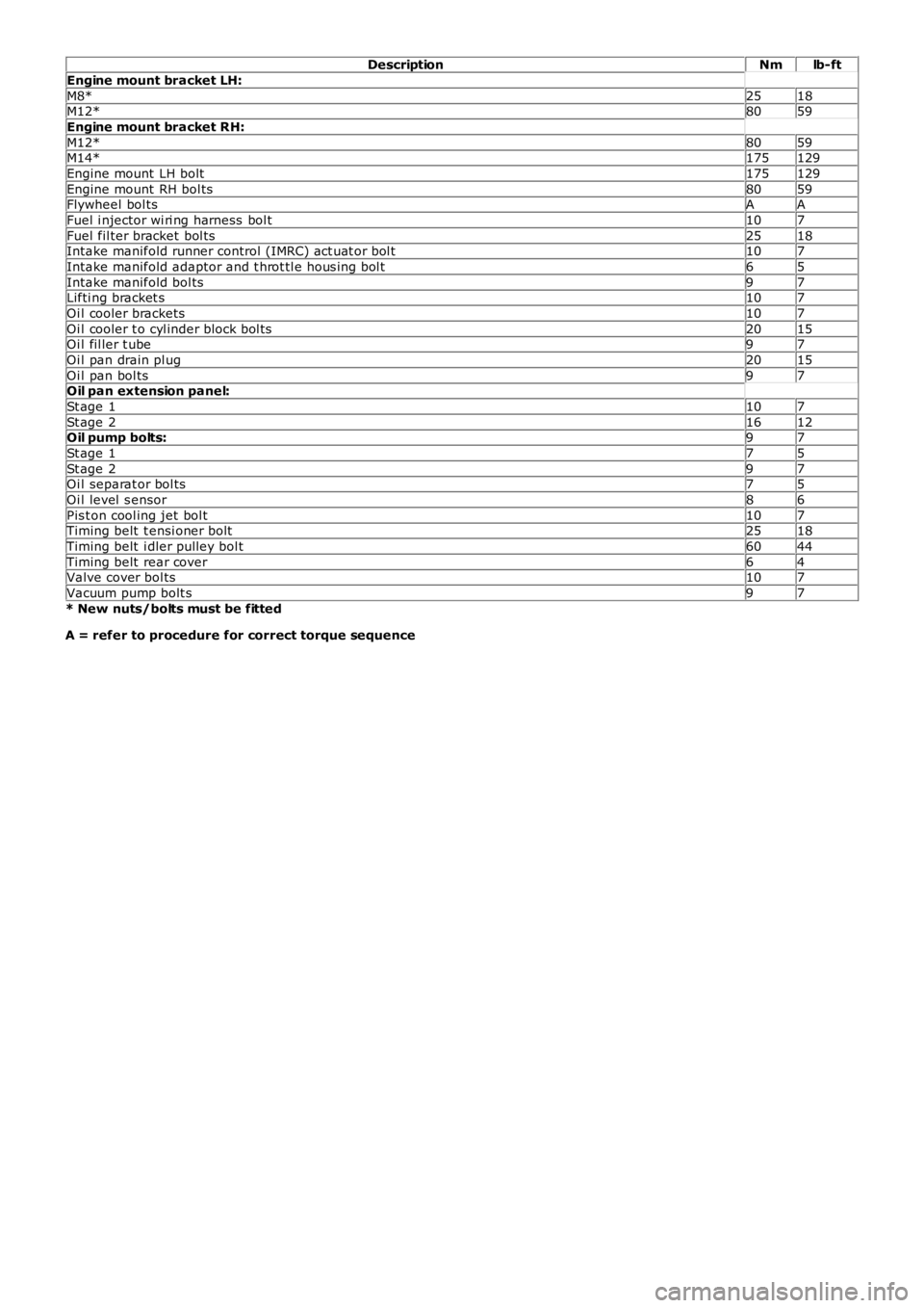
DescriptionNmlb-ft
Engine mount bracket LH:
M8*2518M12*8059
Engine mount bracket RH:
M12*8059M14*175129
Engine mount LH bolt175129
Engine mount RH bol ts8059Flywheel bol tsAA
Fuel i njector wi ri ng harness bol t107
Fuel fil ter bracket bol ts2518Intake manifold runner control (IMRC) act uat or bol t107
Intake manifold adaptor and t hrot tl e hous i ng bol t65
Intake manifold bol ts97Lifti ng bracket s107
Oi l cooler brackets107
Oi l cooler t o cyl inder block bol ts2015Oi l fil ler t ube97
Oi l pan drain pl ug2015
Oi l pan bol ts97Oil pan extension panel:
St age 1107
St age 21612Oil pump bolts:97
St age 175
St age 297Oi l separat or bol ts75
Oi l level s ensor86
Pis t on cool ing jet bol t107Timing belt t ensi oner bolt2518
Timing belt i dler pulley bol t6044
Timing belt rear cover64Valve cover bol ts107
Vacuum pump bolt s97
* New nuts/bolts must be fitted
A = refer to procedure for correct torque sequence
Page 754 of 3229
Publi s hed: 11-May-2011
Engine - TD4 2.2L Diesel - Engine
Des cript ion and Operat ion
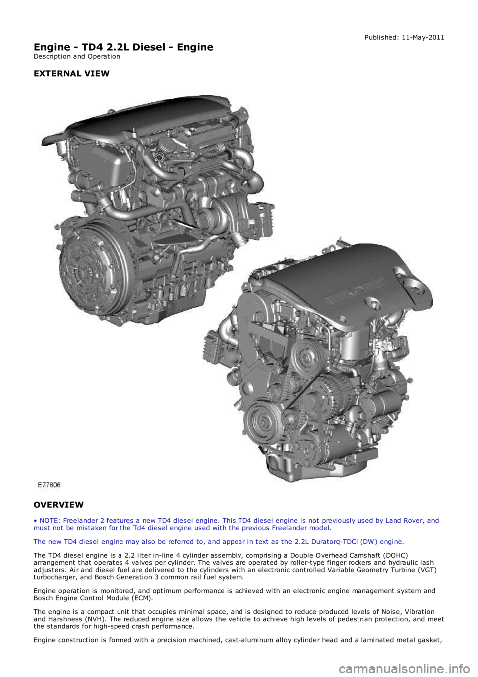
EXTERNAL VIEW
OVERVIEW
• NOTE: Freelander 2 feat ures a new TD4 dies el engine. This TD4 di esel engine i s not previousl y us ed by Land Rover, andmus t not be mis t aken for the Td4 di esel engine us ed wi th t he previ ous Freel ander model.
The new TD4 di es el engi ne may al so be referred to, and appear i n t ext as t he 2.2L Duratorq-TDCi (DW ) engi ne.
The TD4 dies el engi ne is a 2.2 l it er in-line 4 cyl inder as s embly, compri si ng a Double O verhead Cams haft (DOHC)arrangement t hat operat es 4 valves per cyl inder. The valves are operat ed by roller-type fi nger rockers and hydraul ic l as hadjus ters. Ai r and dies el fuel are deli vered to the cyli nders wit h an el ect ronic cont roll ed Vari abl e Geometry Turbine (VGT)t urbocharger, and Bos ch Generati on 3 common rail fuel s ys tem.
Engi ne operati on is monit ored, and opt imum performance is achieved wi th an electronic engi ne management s ys tem andBosch Engine Cont rol Module (ECM).
The engi ne is a compact unit t hat occupies mi nimal s pace, and is des igned t o reduce produced levels of Nois e, Vibrat ionand Hars hness (NVH). The reduced engine si ze allows the vehicle to achieve high level s of pedes t ri an protect ion, and meett he st andards for hi gh-s peed cras h performance.
Engi ne cons t ructi on is formed wit h a preci s ion machined, cas t-alumi num all oy cyl inder head and a lami nat ed met al gas ket,
Page 755 of 3229
s ecurel y bolt ed to the top of a machined cas t-iron cyl inder block. The cylinder head provides t he locati on for t he 16 valves(4 per combus ti on chamber), valve operat ing gear, cams haft s and ti ming gear, fuel inject ors and glow plugs. Dril li ngs andgalleries are formed wi thi n the cyli nder head t o provide lubri cat ing oi l and coolant fl ow.
The cyl inder head is formed wit h the cams haft l ower bearing cap cas t ings , and is enclos ed by a mat ing s t ructural cams haftcover wi th s eali ng gasket. The cams haft cover i s formed wi th the cams haft upper beari ng cap cas t ings , intake ai r fil li ngt racts , and port s for t he cyl inder head cover, crankcas e venti lat ion component s.
An 'L' s haped cyli nder head cover enclos es the s t ructural cams haft cover openings, and i ncorporates t he Posi ti ve Crankcas eVenti lati on Valve (PCV), s afet y val ve and crankcas e vent il ati on connecti ons .
An acous t ic engine cover i s i ns t alled above t he engi ne, and compris es a polypropylene foam layer adhered to theunders ide of a t hermo-plas ti c cover. The cover i s t uned t o abs orb and reduce engine produced nois e t o accept abl e NVHlevels . A hole formed in the rear Left-hand (LH) s ide of t he engine cover provi des the l ocat ion for the engine oi l fil ler cap.
The cyl inder block provides t he locat ion for t he cranks haft and beari ngs , oil cooling jet s, reci procat ing component s , and thecount er-bal ance s haft hous ing. Galleries and drill ings are formed in the cyli nder block for lubri cat ing oi l and coolant fl ow. Acount er-bal ance s haft hous ing i s bolt ed to the unders ide of t he cylinder block and is gear dri ven by the cranks haft . Thecount er-bal ance s haft as s embly reduces engine NVH to provi de a s moot h power out put .
An aluminum oi l pan hous ing and a pres sed st eel oi l pan are s ecured t o t he bot t om of t he cyl inder bl ock. The oil panhous i ng is s ealed and bol ted di rectl y to the cyli nder block. The oil pan is sealed wit h li qui d s ealant and att ached t o t he oilpan hous i ng to provide t he lubricat ion sys tem res ervoir. The lubricat ion sys tem oil pump i s l ocated ins ide t he oil pan andis bol ted t o t he unders ide of t he cyl inder bl ock. The oil pump is chain driven by t he cranks haft .
Engi ne cool ing i s achi eved wit h a pres s uri zed water-cool ant sys tem. An engi ne dri ven coolant pump dis t ri but es t he cool antt hrough gal leries in the cyli nder head and block.
Engi ne produced emis s ions comply wi th European Commis s ion Di recti ve (EUCD) St age 4 legis l at ive requirement s . Theli mit ing of res ul tant emi ss i on pol lut ant s i s acheived by us e of an exhaus t s yst em cat alyti c convert er, an opt ional Di eselPart iculate Filt er (DPF), advanced el ect ronic engine management cont rol , PCV, and Exhaus t Gas Recircul at ion (EGR)s ys t em.
ENGINE STRUCTURE
Page 756 of 3229
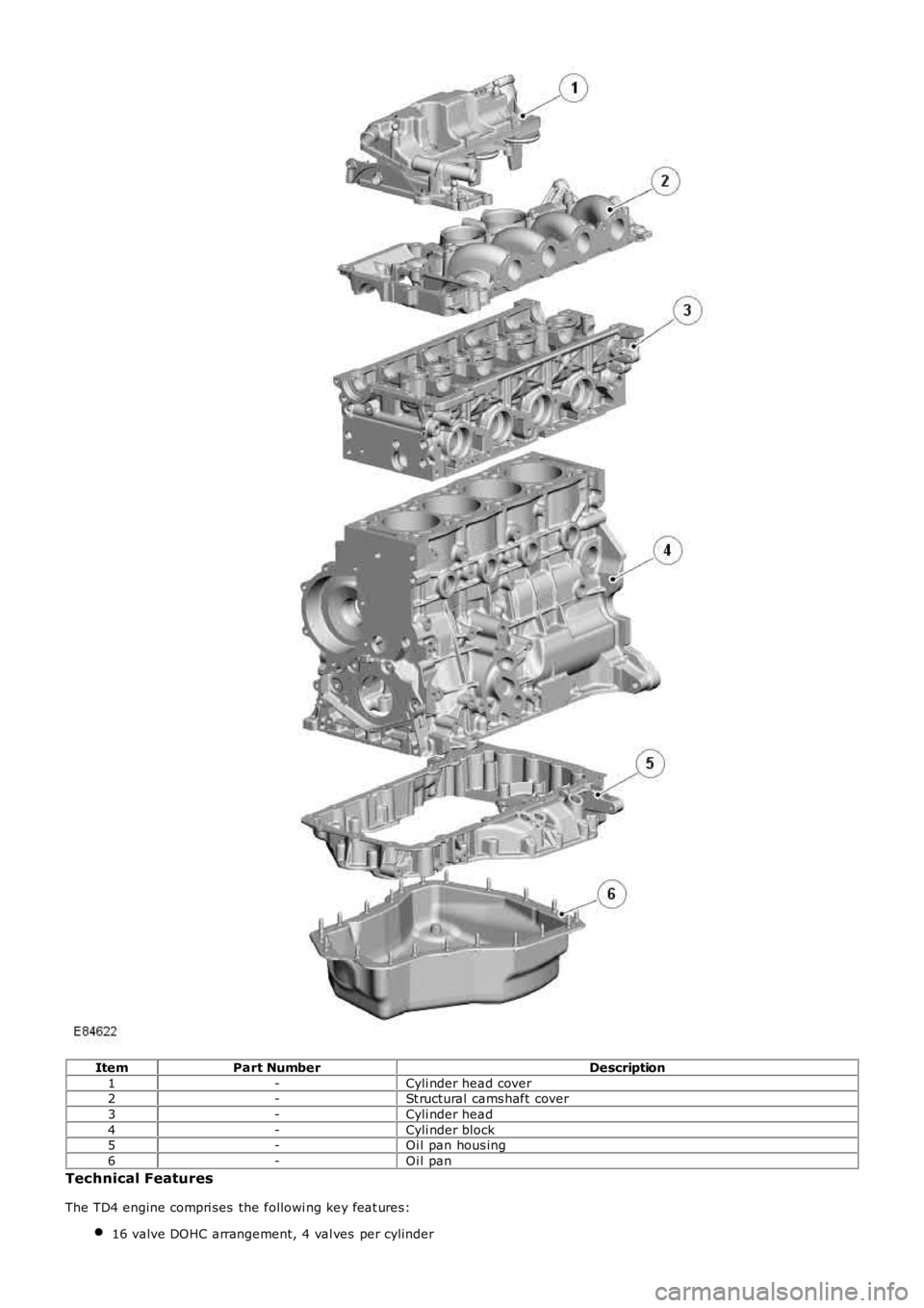
ItemPart NumberDescription
1-Cyli nder head cover2-St ructural cams haft cover
3-Cyli nder head
4-Cyli nder block5-Oi l pan hous ing
6-Oi l pan
Technical Features
The TD4 engine compri ses the followi ng key feat ures:
16 valve DOHC arrangement, 4 val ves per cylinder
Page 757 of 3229
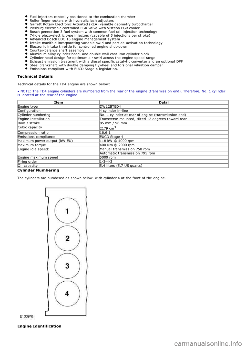
Fuel i njectors cent rall y posi ti oned to the combus ti on chamberRoll er finger rockers wi th hydraul ic l as h adjus t ersGarrett Rot ary Elect ronic Actuat ed (REA) vari abl e geometry t urbochargerPierburg electronic cont rol led EGR val ve wit h Vis t eon EGR cool erBosch generat ion 3 fuel sys t em wi th common fuel rai l i njecti on technol ogy7-hole piezo-electric t ype inject ors (capable of 5 inject ions per st roke)Advanced Bosch EDC 16 engi ne management s ys temInt ake manifold i ncorporati ng variable swi rl and port de-act ivati on t echnologyElectroni c int ake thrott le for cont roll ed engine s hut-downCount er-balance shaft as s emblyAlumi num all oy cyl inder head, and doubl e wall cas t-iron cyl inder bl ockCylinder head des i gn for opti mum ai r s wirl acros s t he engine s peed rangeExhaus t emis s ion t reat ment wit h a di esel s peci fi c cat alyti c convert er and an opti onal DPFSteel crankshaft wit h doubl e damping flywheel and tors i onal vibrat ion damperEmis s ions compli ant wit h EUCD St age 4 legis l at ion.
Technical Details
Technical det ail s for t he TD4 engine are s hown bel ow:
• NOTE: The TD4 engine cyli nders are numbered from t he rear of t he engi ne (t rans mi ssi on end). Therefore, No. 1 cyli nderis locat ed at t he rear of the engine.
ItemDetailEngine t ypeDW 12BTED4
Confi gurati on4 cylinder in-li ne
Cyli nder numberi ngNo. 1 cyl inder at rear of engi ne (t rans mi ss ion end)Engine i ns t allat ionTrans verse mounted, ti lt ed 12 degrees t oward rear
Bore / s troke85 mm / 96 mm
Cubic capaci ty2179 cm3
Compres s ion rati o16.6:1
Emi ss i ons compli anceEUCD St age 4Maximum power out put (kW EU)118 kW @ 4000 rpm
Maximum t orque400 Nm @ 2000 rpm
Engine i dl e s peed:Manual t rans mis s ion 750 rpmAutomat ic t rans mis s ion 795 rpm
Engine maximum s peed5000 rpm
Firing order1-3-4-2Oi l capaci ty5.4 lit ers (5.7 US quart s)
Cylinder Numbering
The cyl inders are numbered as s hown below, wi th cyl inder 4 at the front of t he engi ne.
Engine Identification
Page 758 of 3229

ItemPart NumberDescription
A-Front of engine1-Engine t ype
2-Engine vari ant (manual trans mi s si on)
3-Engine vari ant (automat ic trans mi ss i on)4-Engine s eri al number
Engi ne ident ifi cat ion det ails are l ocat ed on t he lower LH s ide (oil fil ter s ide) of the cyli nder bl ock.
CYLINDER BLOCK COMPONENTS
Page 759 of 3229
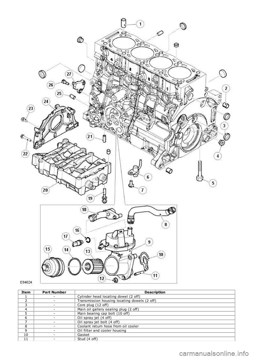
ItemPart NumberDescription
1-Cyli nder head l ocati ng dowel (2 off)2-Trans mi ss i on hous ing locat ing dowel s (2 off)
3-Core plug (12 off)
4-Mai n oil gall ery s ealing pl ug (2 off)5-Mai n bearing cap bolt (10 off)
6-Oi l spray jet (4 off)
7-Oi l spray jet bolt (4 off)8-Coolant ret urn hos e from oil cool er
9-Oi l fi lt er and cooler housi ng
10-Gas ket11-St ud (4 off)
Page 760 of 3229
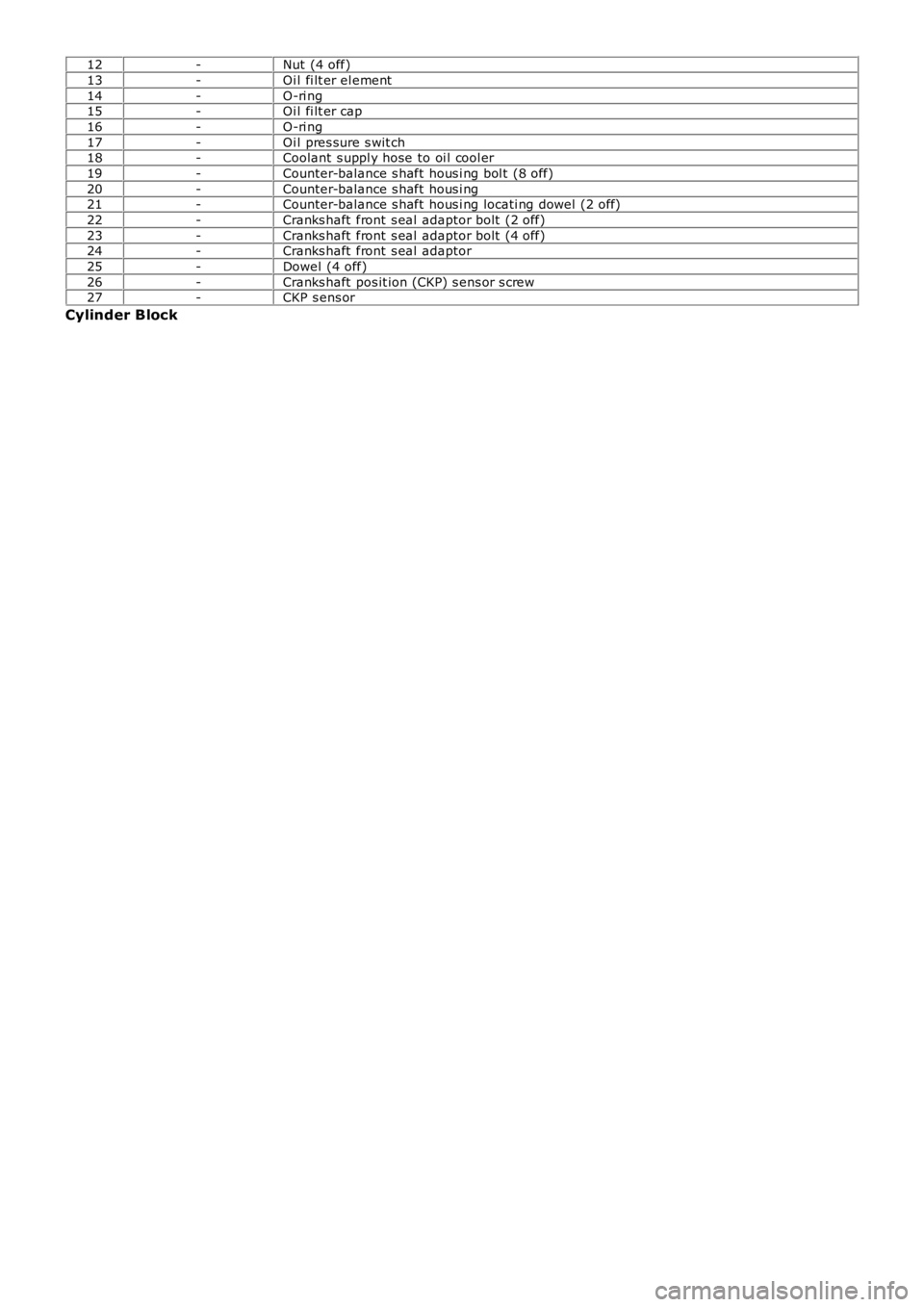
12-Nut (4 off)
13-Oi l fi lt er el ement
14-O-ri ng15-Oi l fi lt er cap
16-O-ri ng
17-Oi l pres sure s wit ch18-Coolant s uppl y hose to oi l cool er
19-Counter-balance s haft hous i ng bol t (8 off)
20-Counter-balance s haft hous i ng21-Counter-balance s haft hous i ng locati ng dowel (2 off)
22-Cranks haft front s eal adaptor bolt (2 off)
23-Cranks haft front s eal adaptor bolt (4 off)24-Cranks haft front s eal adaptor
25-Dowel (4 off)
26-Cranks haft pos it ion (CKP) s ens or s crew27-CKP s ens or
Cylinder Block