LEXUS LS430 2003 Factory Repair Manual
Manufacturer: LEXUS, Model Year: 2003,
Model line: LS430,
Model: LEXUS LS430 2003
Pages: 4500, PDF Size: 87.45 MB
LEXUS LS430 2003 Factory Repair Manual
LS430 2003
LEXUS
LEXUS
https://www.carmanualsonline.info/img/36/57050/w960_57050-0.png
LEXUS LS430 2003 Factory Repair Manual
Trending: mileage, change time, navigation update, B2776, damper, B2419 bean, fuel system
Page 1101 of 4500
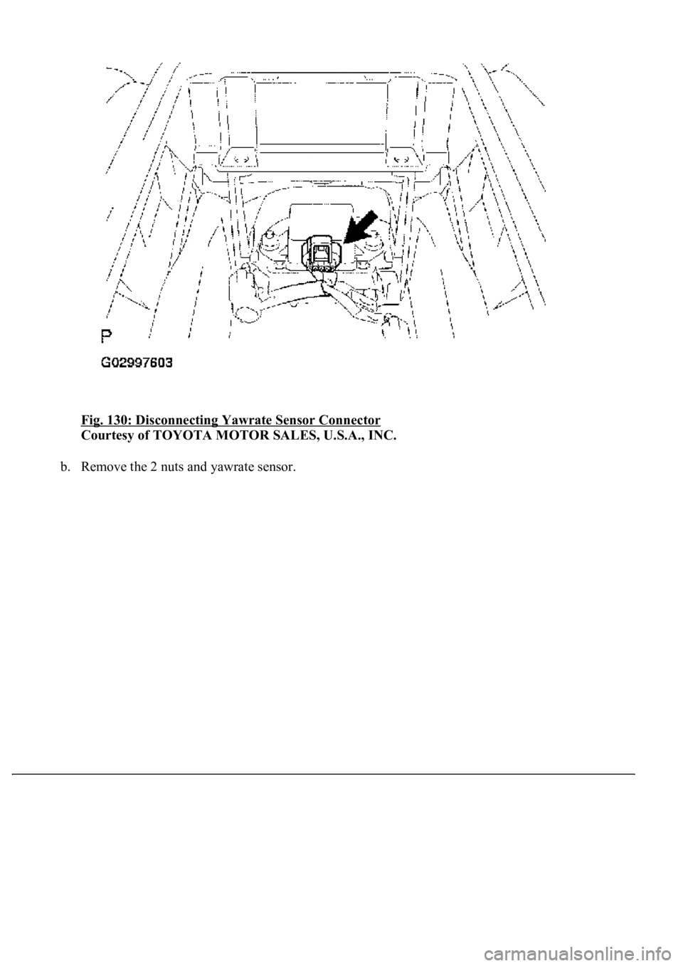
Fig. 130: Disconnecting Yawrate Sensor Connector
Courtesy of TOYOTA MOTOR SALES, U.S.A., INC.
b. Remove the 2 nuts and yawrate sensor.
Page 1102 of 4500
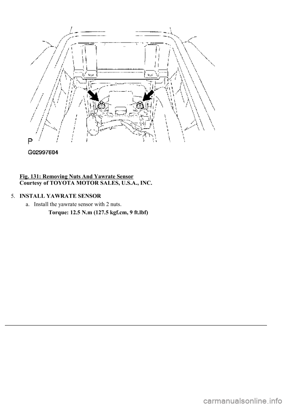
Fig. 131: Removing Nuts And Yawrate Sensor
Courtesy of TOYOTA MOTOR SALES, U.S.A., INC.
5.INSTALL YAWRATE SENSOR
a. Install the yawrate sensor with 2 nuts.
Torque: 12.5 N.m (127.5 kgf.cm, 9 ft.lbf)
Page 1103 of 4500
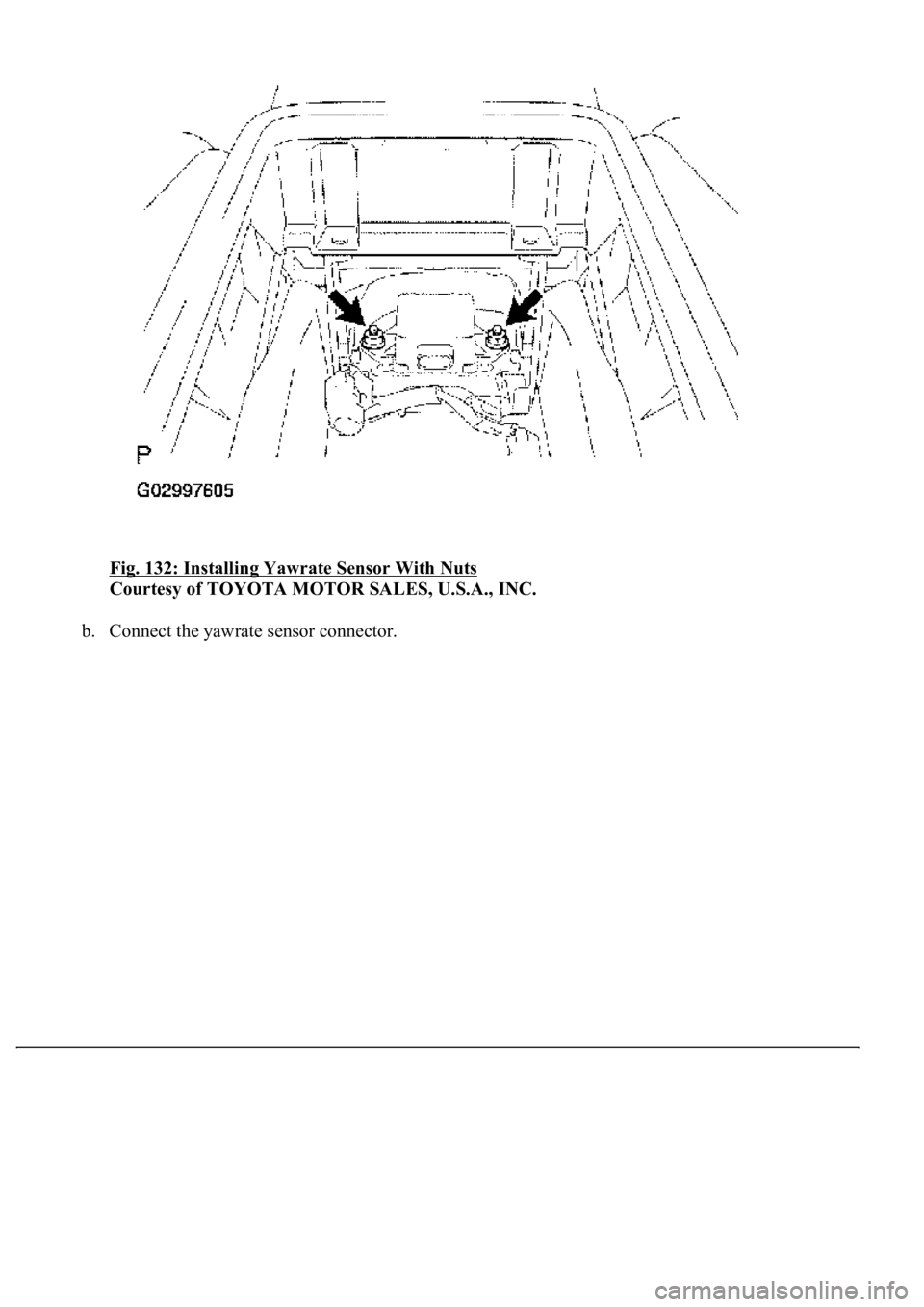
Fig. 132: Installing Yawrate Sensor With Nuts
Courtesy of TOYOTA MOTOR SALES, U.S.A., INC.
b. Connect the yawrate sensor connector.
Page 1104 of 4500
Fig. 133: Connecting Yawrate Sensor Connector
Courtesy of TOYOTA MOTOR SALES, U.S.A., INC.
6.INSTALL REAR CONSOLE ARMREST ASSY (SEE REPLACEMENT
)
7.INSTALL CONSOLE BOX CARPET
8.INSTALL CONSOLE UPPER REAR PANEL SUB-ASSY (SEE REPLACEMENT
)
9.PERFORM YAWRATE SENSOR ZERO POINT CALIBRATION (SEE CALIBRATION
)
REPLACEMENT
1.(SEE PRECAUTION
)
2.SEPARATE BATTERY NEGATIVE TERMINAL (SEE PRECAUTION
)
3.PLACE FRONT WHEELS FACING STRAIGHT AHEAD
4.REMOVE HORN BUTTON ASSY (SEE OVERHAUL
)
5.REMOVE STEERING WHEEL ASSY (SEE OVERHAUL
)
<00360036003700030013001c001c001800130010001800130013001400160003000b0013001c001c00180014001000130018001300140013000f00030013001c001c00180015001000130018001300140013000f00030013001c001c001800160010001300
18001300150013000f00030013001c001c0018001700100013[5021)
6.REMOVE STEERING COLUMN COVER (SEE OVERHAUL
)
Page 1105 of 4500
7.REMOVE SPIRAL CABLE SUB-ASSY (SEE REPLACEMENT )
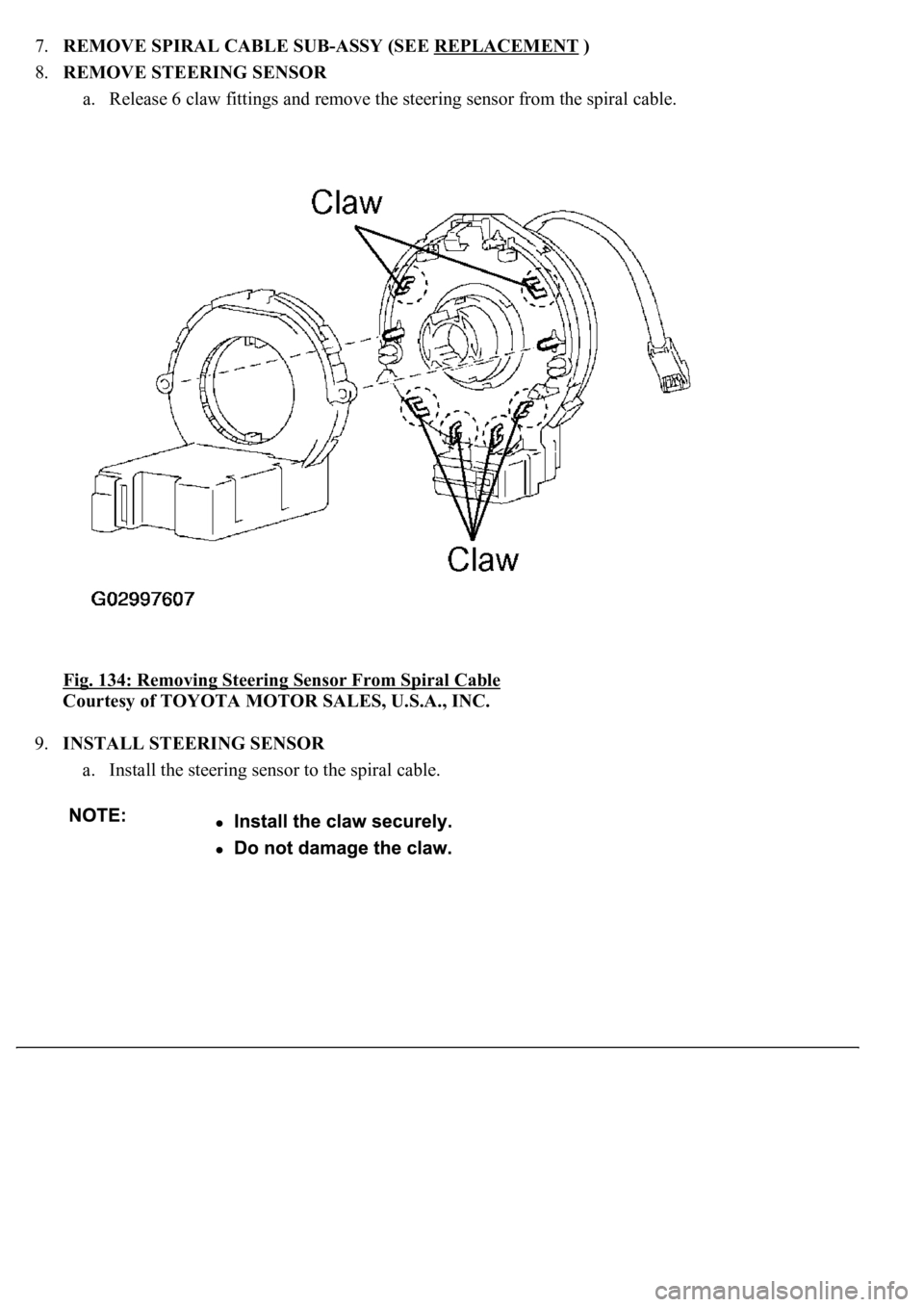
8.REMOVE STEERING SENSOR
a. Release 6 claw fittings and remove the steering sensor from the spiral cable.
Fig. 134: Removing Steering Sensor From Spiral Cable
Courtesy of TOYOTA MOTOR SALES, U.S.A., INC.
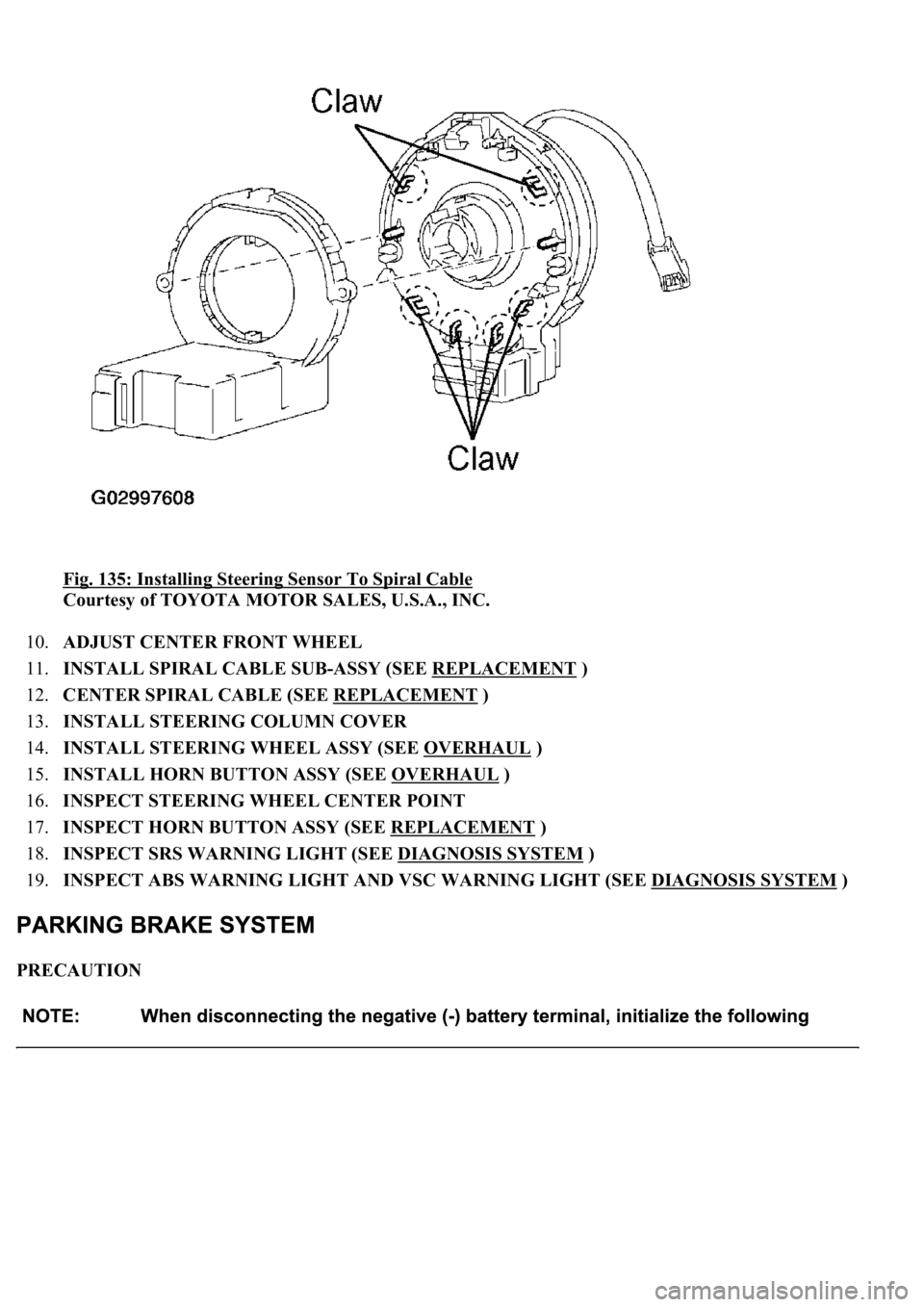
9.INSTALL STEERING SENSOR
a. Install the steering sensor to the spiral cable.
Page 1106 of 4500
Fig. 135: Installing Steering Sensor To Spiral Cable
Courtesy of TOYOTA MOTOR SALES, U.S.A., INC.
10.ADJUST CENTER FRONT WHEEL
11.INSTALL SPIRAL CABLE SUB-ASSY (SEE REPLACEMENT
)
12.CENTER SPIRAL CABLE (SEE REPLACEMENT
)
13.INSTALL STEERING COLUMN COVER
14.INSTALL STEERING WHEEL ASSY (SEE OVERHAUL
)
15.INSTALL HORN BUTTON ASSY (SEE OVERHAUL
)
16.INSPECT STEERING WHEEL CENTER POINT
17.INSPECT HORN BUTTON ASSY (SEE REPLACEMENT
)
18.INSPECT SRS WARNING LIGHT (SEE DIAGNOSIS SYSTEM
)
19.INSPECT ABS WARNING LIGHT AND VSC WARNING LIGHT (SEE DIAGNOSIS SYSTEM
)
PRECAUTION
Page 1107 of 4500
SYSTEM INDEX
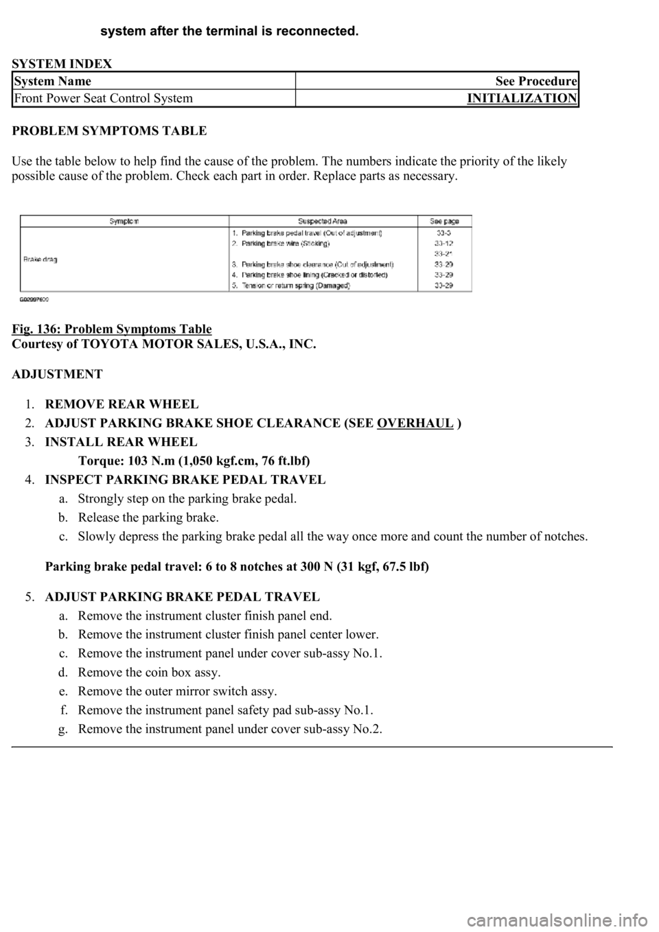
PROBLEM SYMPTOMS TABLE
<00380056004800030057004b00480003005700440045004f0048000300450048004f0052005a0003005700520003004b0048004f005300030049004c0051004700030057004b004800030046004400580056004800030052004900030057004b0048000300
53005500520045004f00480050001100030037004b00480003[numbers indicate the priority of the likely
possible cause of the problem. Check each part in order. Replace parts as necessary.
Fig. 136: Problem Symptoms Table
Courtesy of TOYOTA MOTOR SALES, U.S.A., INC.
ADJUSTMENT
1.REMOVE REAR WHEEL
2.ADJUST PARKING BRAKE SHOE CLEARANCE (SEE OVERHAUL
)
3.INSTALL REAR WHEEL
Torque: 103 N.m (1,050 kgf.cm, 76 ft.lbf)
4.INSPECT PARKING BRAKE PEDAL TRAVEL
a. Strongly step on the parking brake pedal.
b. Release the parking brake.
c. Slowly depress the parking brake pedal all the way once more and count the number of notches.
Parking brake pedal travel: 6 to 8 notches at 300 N (31 kgf, 67.5 lbf)
5.ADJUST PARKING BRAKE PEDAL TRAVEL
a. Remove the instrument cluster finish panel end.
b. Remove the instrument cluster finish panel center lower.
c. Remove the instrument panel under cover sub-assy No.1.
d. Remove the coin box assy.
e. Remove the outer mirror switch assy.
f. Remove the instrument panel safety pad sub-assy No.1.
g. Remove the instrument panel under cover sub-assy No.2.
System NameSee Procedure
Front Power Seat Control SystemINITIALIZATION
Page 1108 of 4500
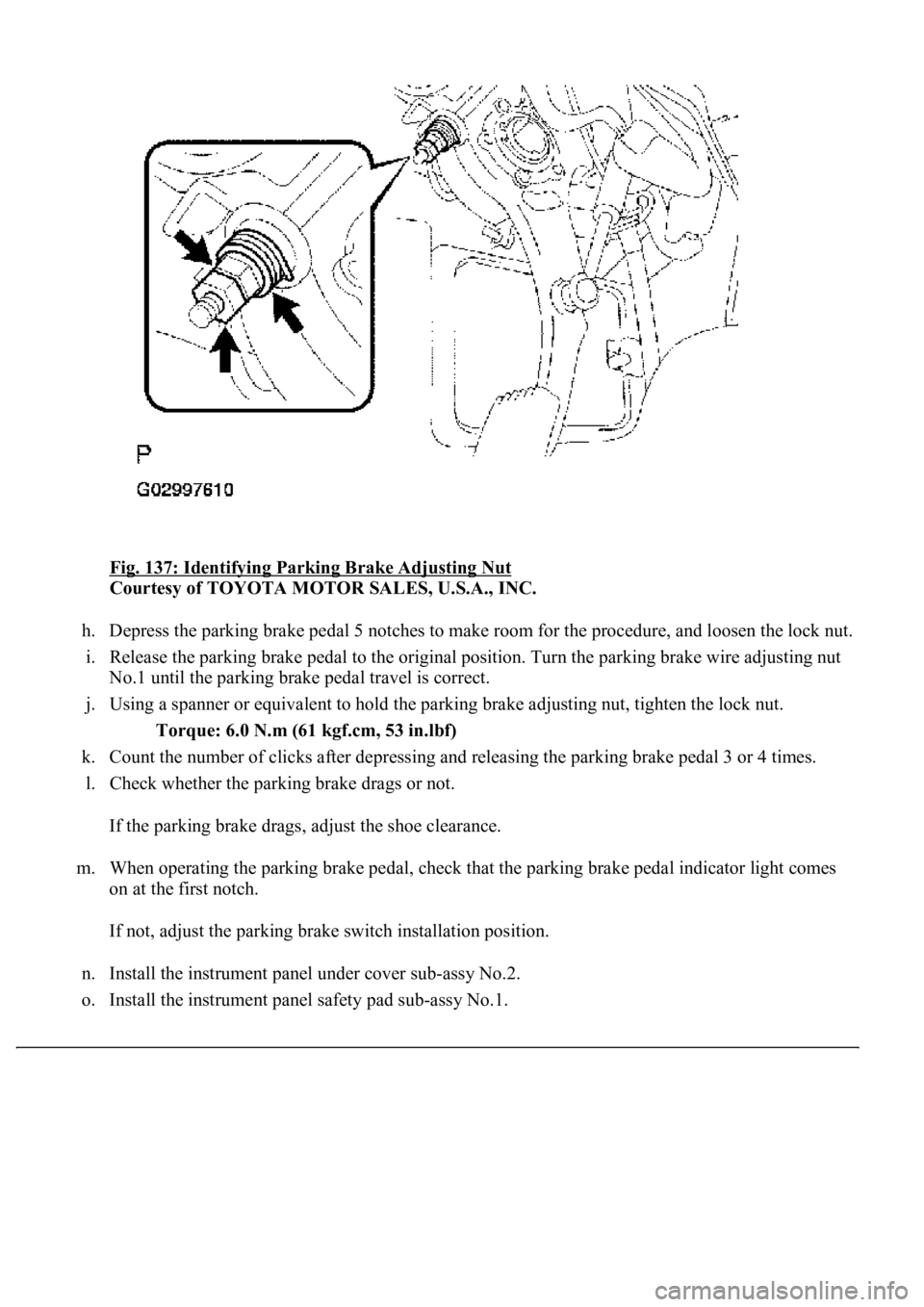
Fig. 137: Identifying Parking Brake Adjusting Nut
Courtesy of TOYOTA MOTOR SALES, U.S.A., INC.
h. Depress the parking brake pedal 5 notches to make room for the procedure, and loosen the lock nut.
i. Release the parking brake pedal to the original position. Turn the parking brake wire adjusting nut
<00310052001100140003005800510057004c004f00030057004b00480003005300440055004e004c0051004a0003004500550044004e004800030053004800470044004f000300570055004400590048004f0003004c005600030046005200550055004800
460057001100030003[
j. Using a spanner or equivalent to hold the parking brake adjusting nut, tighten the lock nut.
Torque: 6.0 N.m (61 kgf.cm, 53 in.lbf)
k. Count the number of clicks after depressing and releasing the parking brake pedal 3 or 4 times.
l. Check whether the parking brake drags or not.
If the parking brake drags, adjust the shoe clearance.
m. When operating the parking brake pedal, check that the parking brake pedal indicator light comes
on at the first notch.
If not, adjust the parking brake switch installation position.
n. Install the instrument panel under cover sub-assy No.2.
o. Install the instrument panel safet
y pad sub-assy No.1.
Page 1109 of 4500
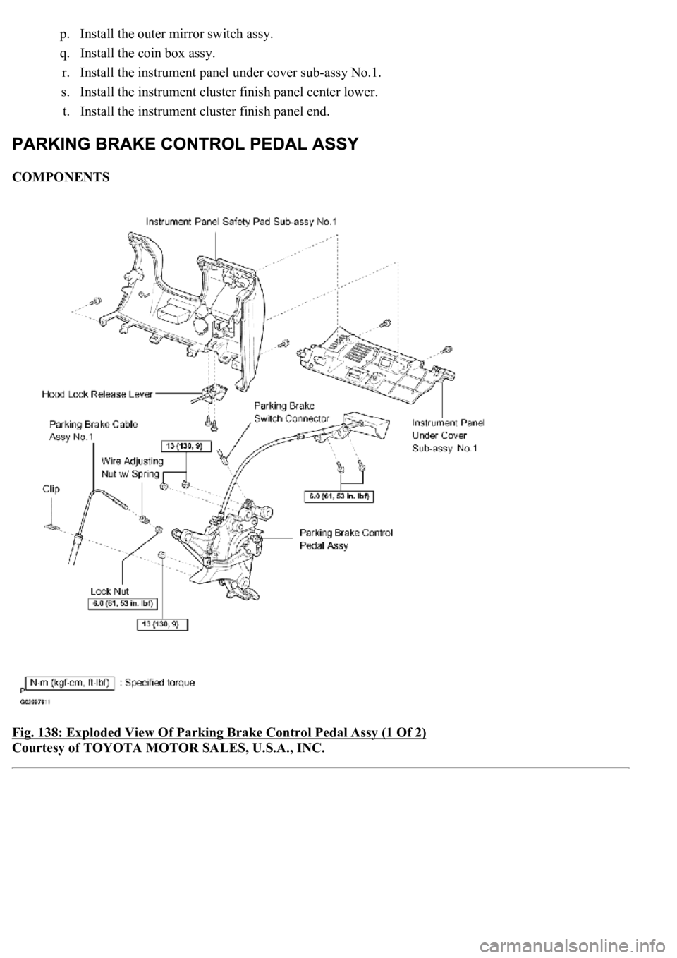
p. Install the outer mirror switch assy.
q. Install the coin box assy.
r. Install the instrument panel under cover sub-assy No.1.
s. Install the instrument cluster finish panel center lower.
t. Install the instrument cluster finish panel end.
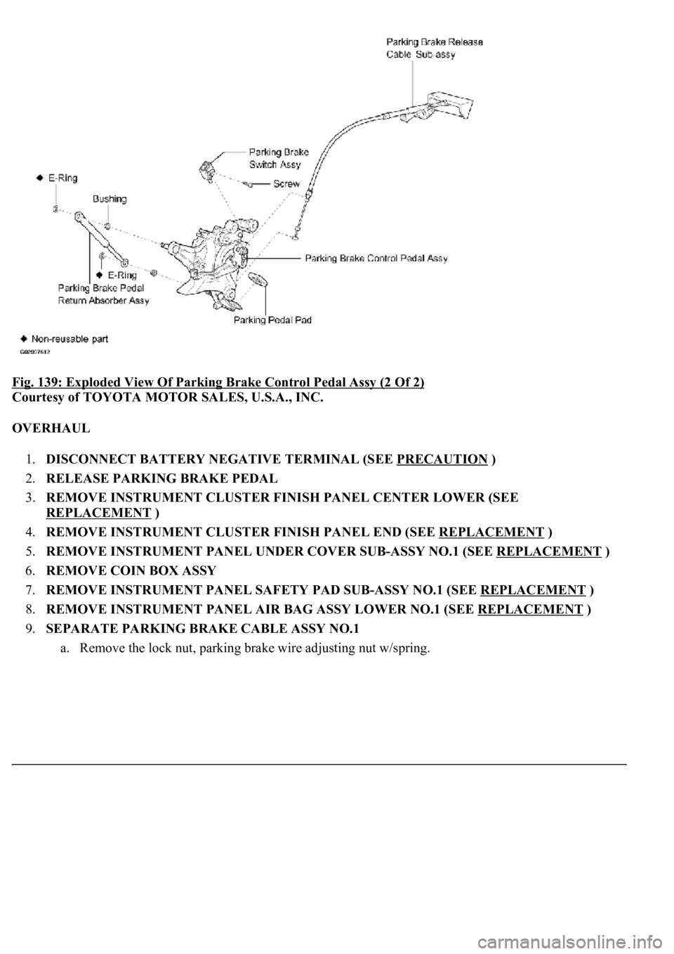
COMPONENTS
Fig. 138: Exploded View Of Parking Brake Control Pedal Assy (1 Of 2)
Courtesy of TOYOTA MOTOR SALES, U.S.A., INC.
Page 1110 of 4500
Fig. 139: Exploded View Of Parking Brake Control Pedal Assy (2 Of 2)
Courtesy of TOYOTA MOTOR SALES, U.S.A., INC.
OVERHAUL
1.DISCONNECT BATTERY NEGATIVE TERMINAL (SEE PRECAUTION
)
2.RELEASE PARKING BRAKE PEDAL
3.REMOVE INSTRUMENT CLUSTER FINISH PANEL CENTER LOWER (SEE
REPLACEMENT
)
4.REMOVE INSTRUMENT CLUSTER FINISH PANEL END (SEE REPLACEMENT
)
5.REMOVE INSTRUMENT PANEL UNDER COVER SUB-ASSY NO.1 (SEE REPLACEMENT
)
6.REMOVE COIN BOX ASSY
7.REMOVE INSTRUMENT PANEL SAFETY PAD SUB-ASSY NO.1 (SEE REPLACEMENT
)
8.REMOVE INSTRUMENT PANEL AIR BAG ASSY LOWER NO.1 (SEE REPLACEMENT
)
9.SEPARATE PARKING BRAKE CABLE ASSY NO.1
a. Remove the lock nut, parkin
g brake wire adjusting nut w/spring.
Trending: Air Conditioning Compressor, zero point calibration, water pump, garage door opener, roof, Door lock actuator, ESP
