LEXUS LS430 2003 Factory Repair Manual
LS430 2003
LEXUS
LEXUS
https://www.carmanualsonline.info/img/36/57050/w960_57050-0.png
LEXUS LS430 2003 Factory Repair Manual
Page 907 of 4500
Fig. 85: Installing 20 Bolts
Courtesy of TOYOTA MOTOR SALES, U.S.A., INC.
8.INSTALL TRANSMISSION WIRE
a. Coat a new O-ring of the ATF temperature sensor with ATF.
b. Connect the 9 connectors to the solenoid valves.
c. Install the 2 clamps with the 2 bolts.
Torque: 10 N.m (100 kgf.cm, 7 ft.lbf)
d. Install the ATF temperature sensor and lock plate with the bolt.
Torque: 10 N.m (100 kgf.cm, 7 ft.lbf)
Page 908 of 4500
Fig. 86: Installing ATF Temperature Sensor And Lock Plate With Bolt
Courtesy of TOYOTA MOTOR SALES, U.S.A., INC.
9.INSTALL VALVE BODY OIL STRAINER ASSY
a. Coat a new O-ring with ATF.
b. Install the O-ring.
Page 913 of 4500
6.REMOVE INSTRUMENT PANEL SAFETY PAD SUB-ASSY NO.1 (SEE REPLACEMENT )
7.REMOVE INSTRUMENT PANEL CUP HOLDER ASSY (SEE REPLACEMENT
)
8.REMOVE CONSOLE UPPER REAR PANEL SUB-ASSY (SEE REPLACEMENT
)
9.REMOVE CONSOLE BOX CARPET (SEE REPLACEMENT
)
10.REMOVE REAR CONSOLE ARMREST ASSY (SEE REPLACEMENT
)
11.REMOVE INSTRUMENT PANEL FINISH PANEL LOWER CENTER (SEE REPLACEMENT
)
12.REMOVE INSTRUMENT CLUSTER FINISH PANEL SUB-ASSY CENTER (SEE
REPLACEMENT
)
13.REMOVE CONSOLE PANEL SUB-ASSY UPPER (SEE REPLACEMENT
)
14.REMOVE CONSOLE BOX (SEE REPLACEMENT
)
15.SEPARATE OXYGEN SENSOR (SEE REPLACEMENT
)
16.REMOVE EXHAUST PIPE ASSY (SEE REPLACEMENT
)
17.REMOVE PROPELLER W/CENTER BEARING SHAFT ASSY (SEE OVERHAUL
)
18.DRAIN AUTOMATIC TRANSMISSION FLUID
a. Remove the drain plug, gasket and drain the ATF.
b. Install a new gasket and the drain plug.
Torque: 20 N.m (205 kgf.cm, 15 ft.lbf)
19.REMOVE AUTOMATIC TRANSMISSION FLANGE YOKE ASSY
a. Using SST and a hammer, loosen the staked part of the nut.
SST 09930-00010
HINT:
Move the shift lever to the P position.
Page 1084 of 4500
18.INSTALL FRONT WHEEL
19.CONNECT ENGINE ROOM NO.3 R/B
a. Install the engine room No.3 R/B and bolt.
20.INSTALL ENGINE ROOM SIDE COVER
21.PERFORM YAWRATE SENSOR ZERO POINT CALIBRATION AND TEST MODE
COMPONENTS
Page 1085 of 4500
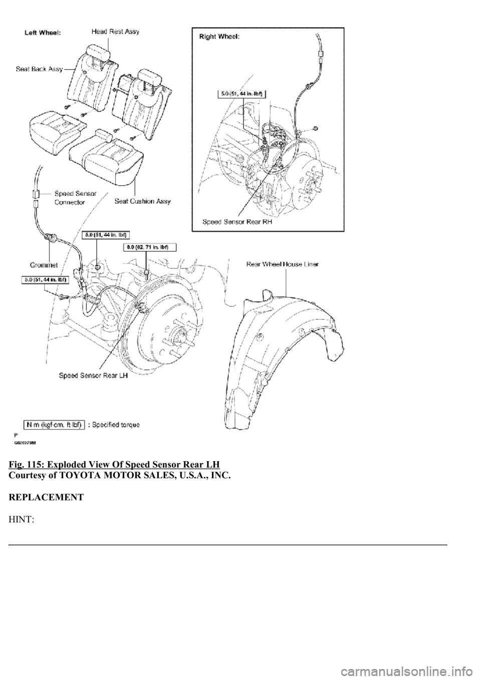
Fig. 115: Exploded View Of Speed Sensor Rear LH
Courtesy of TOYOTA MOTOR SALES, U.S.A., INC.
REPLACEMENT
HINT:
Page 1086 of 4500
Replace the RH side by using the same procedures as for the LH side.
The procedures listed below are for the LH side.
1.REMOVE REAR SEAT CUSHION ASSY (SEE OVERHAUL
- FIXED TYPE or OVERHAUL -
POWER ADJUSTER TYPE
)
2.REMOVE REAR SEAT HEAD REST ASSY (SEE OVERHAUL
- FIXED TYPE or OVERHAUL -
POWER ADJUSTER TYPE )
3.REMOVE REAR SEATBACK ASSY (SEE OVERHAUL
- FIXED TYPE or OVERHAUL -
POWER ADJUSTER TYPE
)
4.REMOVE REAR WHEEL
5.REMOVE REAR WHEEL HOUSE LH LINER
6.REMOVE SPEED SENSOR REAR LH
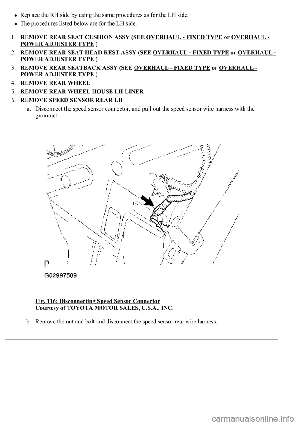
a. Disconnect the speed sensor connector, and pull out the speed sensor wire harness with the
grommet.
Fig. 116: Disconnecting Speed Sensor Connector
Courtesy of TOYOTA MOTOR SALES, U.S.A., INC.
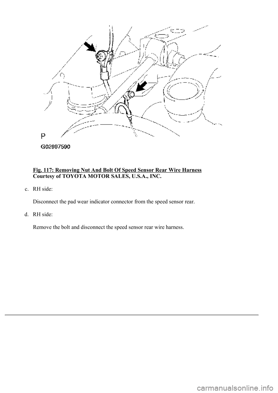
b. Remove the nut and bolt and disconnect the speed sensor rear wire harness.
Page 1087 of 4500
Fig. 117: Removing Nut And Bolt Of Speed Sensor Rear Wire Harness
Courtesy of TOYOTA MOTOR SALES, U.S.A., INC.
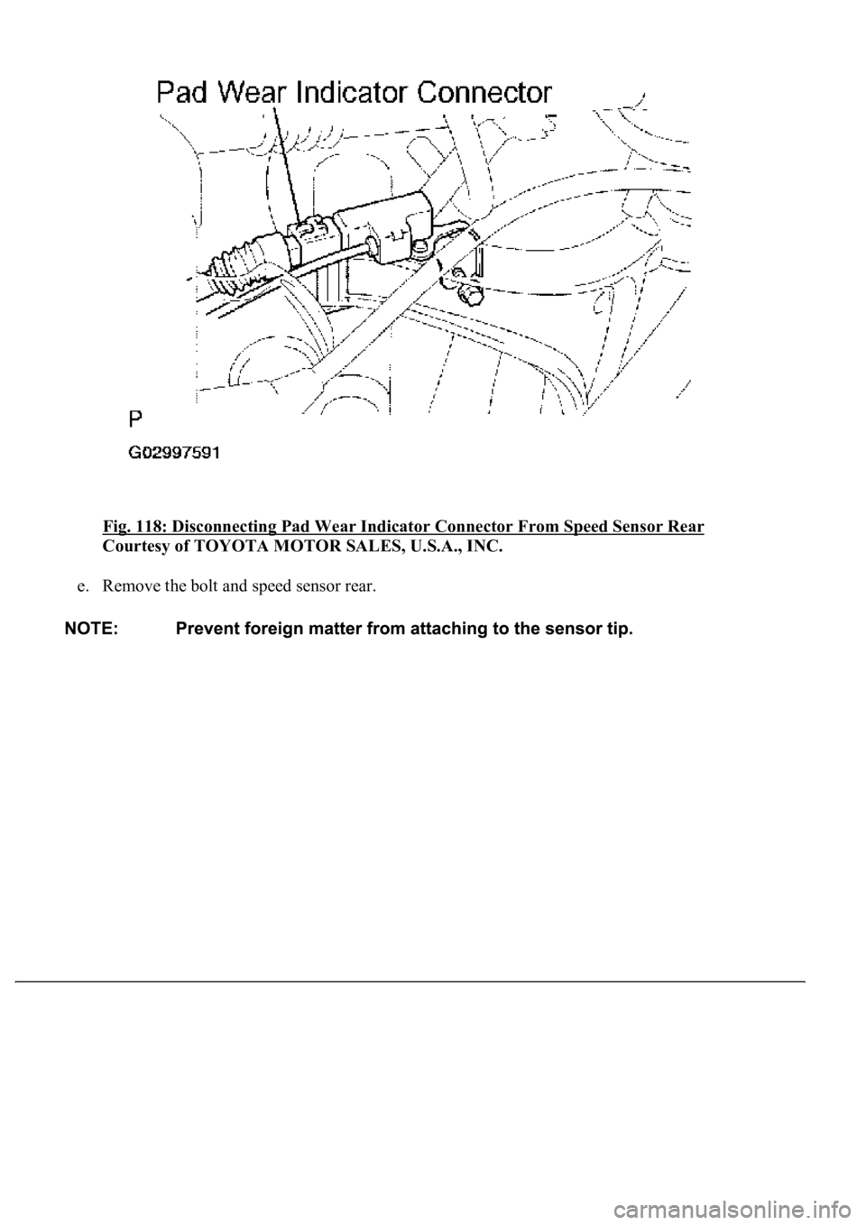
c. RH side:
Disconnect the pad wear indicator connector from the speed sensor rear.
d. RH side:
Remove the bolt and disconnect the speed sensor rear wire harness.
Page 1088 of 4500
Fig. 118: Disconnecting Pad Wear Indicator Connector From Speed Sensor Rear
Courtesy of TOYOTA MOTOR SALES, U.S.A., INC.
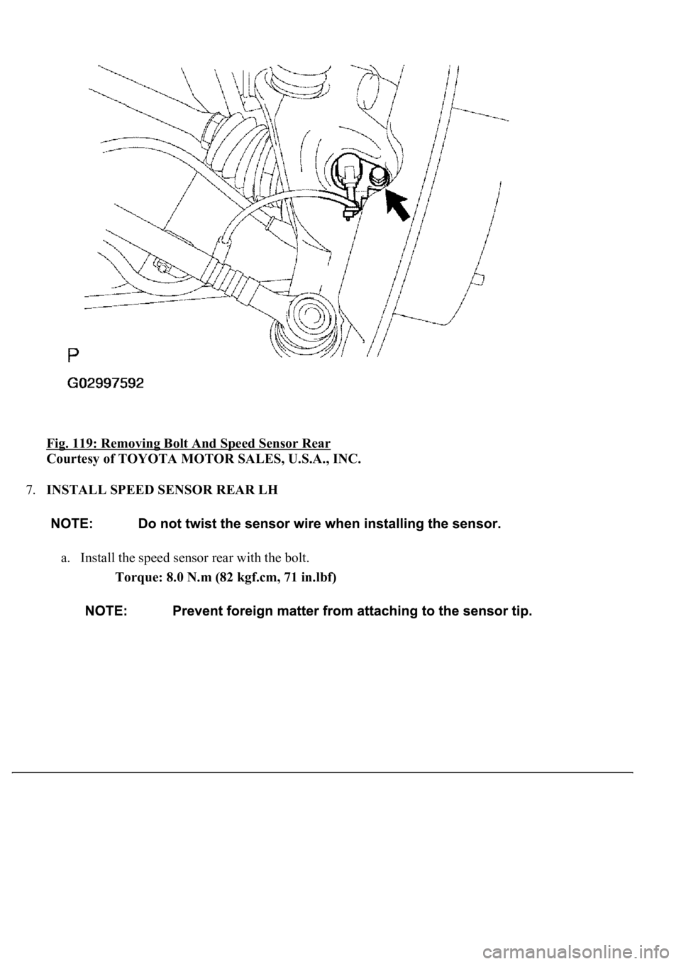
e. Remove the bolt and speed sensor rear.
Page 1089 of 4500
Fig. 119: Removing Bolt And Speed Sensor Rear
Courtesy of TOYOTA MOTOR SALES, U.S.A., INC.
7.INSTALL SPEED SENSOR REAR LH
a. Install the speed sensor rear with the bolt.
Torque: 8.0 N.m (82 kgf.cm, 71 in.lbf)
Page 1090 of 4500
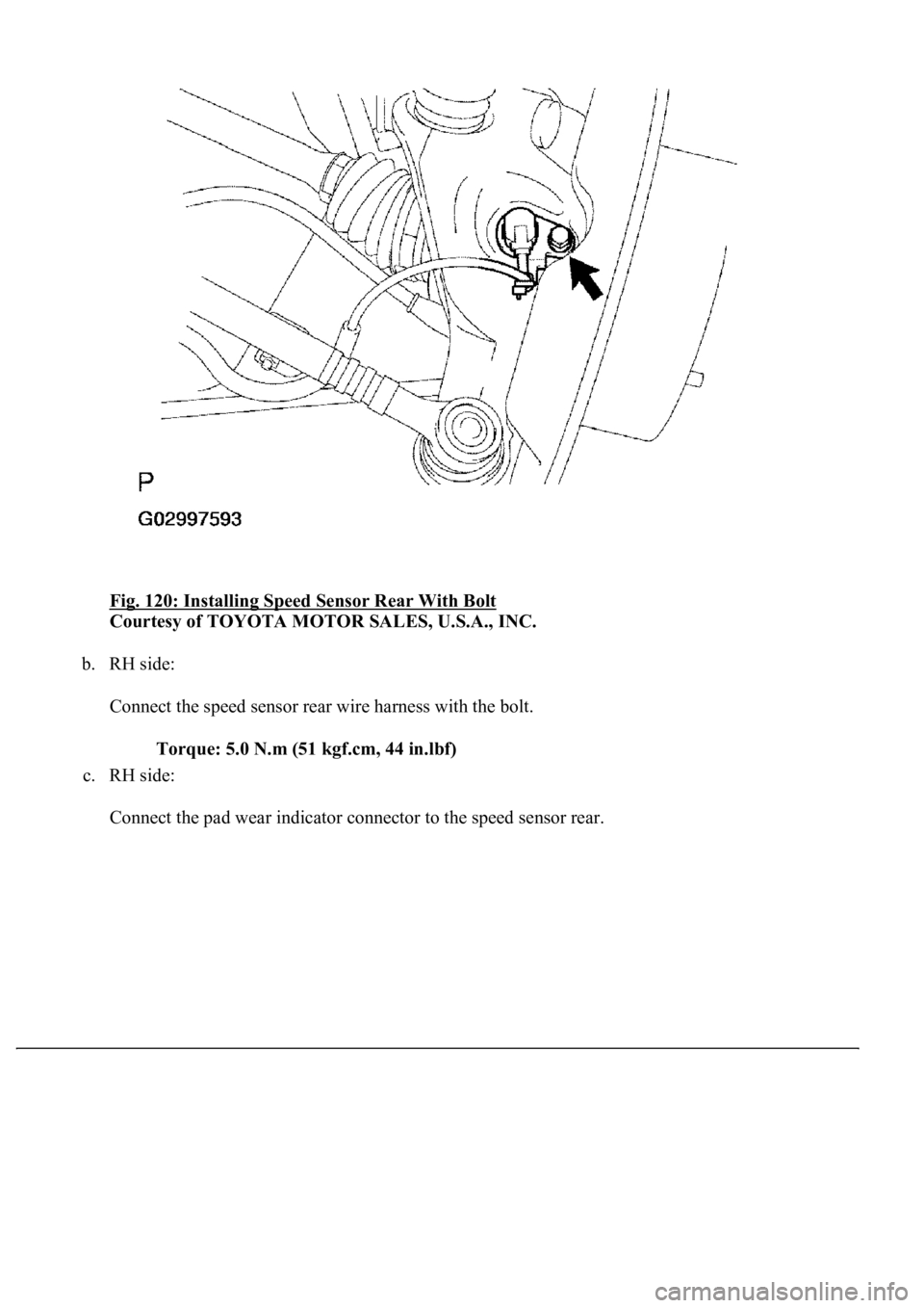
Fig. 120: Installing Speed Sensor Rear With Bolt
Courtesy of TOYOTA MOTOR SALES, U.S.A., INC.
b. RH side:
Connect the speed sensor rear wire harness with the bolt.
Torque: 5.0 N.m (51 kgf.cm, 44 in.lbf)
c. RH side:
Connect the pad wear indicator connector to the speed sensor rear.


