LEXUS LS430 2003 Factory Repair Manual
Manufacturer: LEXUS, Model Year: 2003,
Model line: LS430,
Model: LEXUS LS430 2003
Pages: 4500, PDF Size: 87.45 MB
LEXUS LS430 2003 Factory Repair Manual
LS430 2003
LEXUS
LEXUS
https://www.carmanualsonline.info/img/36/57050/w960_57050-0.png
LEXUS LS430 2003 Factory Repair Manual
Trending: coolant, Navi, airbag, check transmission fluid, heating, Conditioner, checking oil
Page 2971 of 4500
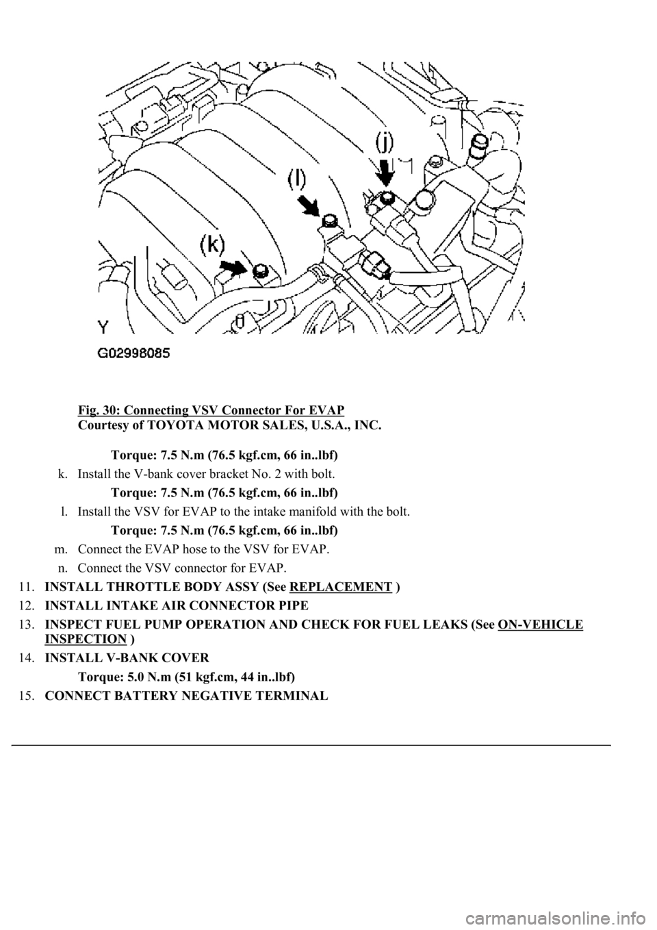
Fig. 30: Connecting VSV Connector For EVAP
Courtesy of TOYOTA MOTOR SALES, U.S.A., INC.
Torque: 7.5 N.m (76.5 kgf.cm, 66 in..lbf)
k. Install the V-bank cover bracket No. 2 with bolt.
Torque: 7.5 N.m (76.5 kgf.cm, 66 in..lbf)
l. Install the VSV for EVAP to the intake manifold with the bolt.
Torque: 7.5 N.m (76.5 kgf.cm, 66 in..lbf)
m. Connect the EVAP hose to the VSV for EVAP.
n. Connect the VSV connector for EVAP.
11.INSTALL THROTTLE BODY ASSY (See REPLACEMENT
)
12.INSTALL INTAKE AIR CONNECTOR PIPE
13.INSPECT FUEL PUMP OPERATION AND CHECK FOR FUEL LEAKS (See ON
-VEHICLE
INSPECTION )
14.INSTALL V-BANK COVER
Torque: 5.0 N.m (51 kgf.cm, 44 in..lbf)
15.CONNECT BATTERY NEGATIVE TERMINAL
Page 2972 of 4500
16.REFILL ENGINE COOLANT (See ENGINE COOLANT )
17.CHECK FOR ENGINE COOLANT LEAKS (See ON
-VEHICLE INSPECTION )
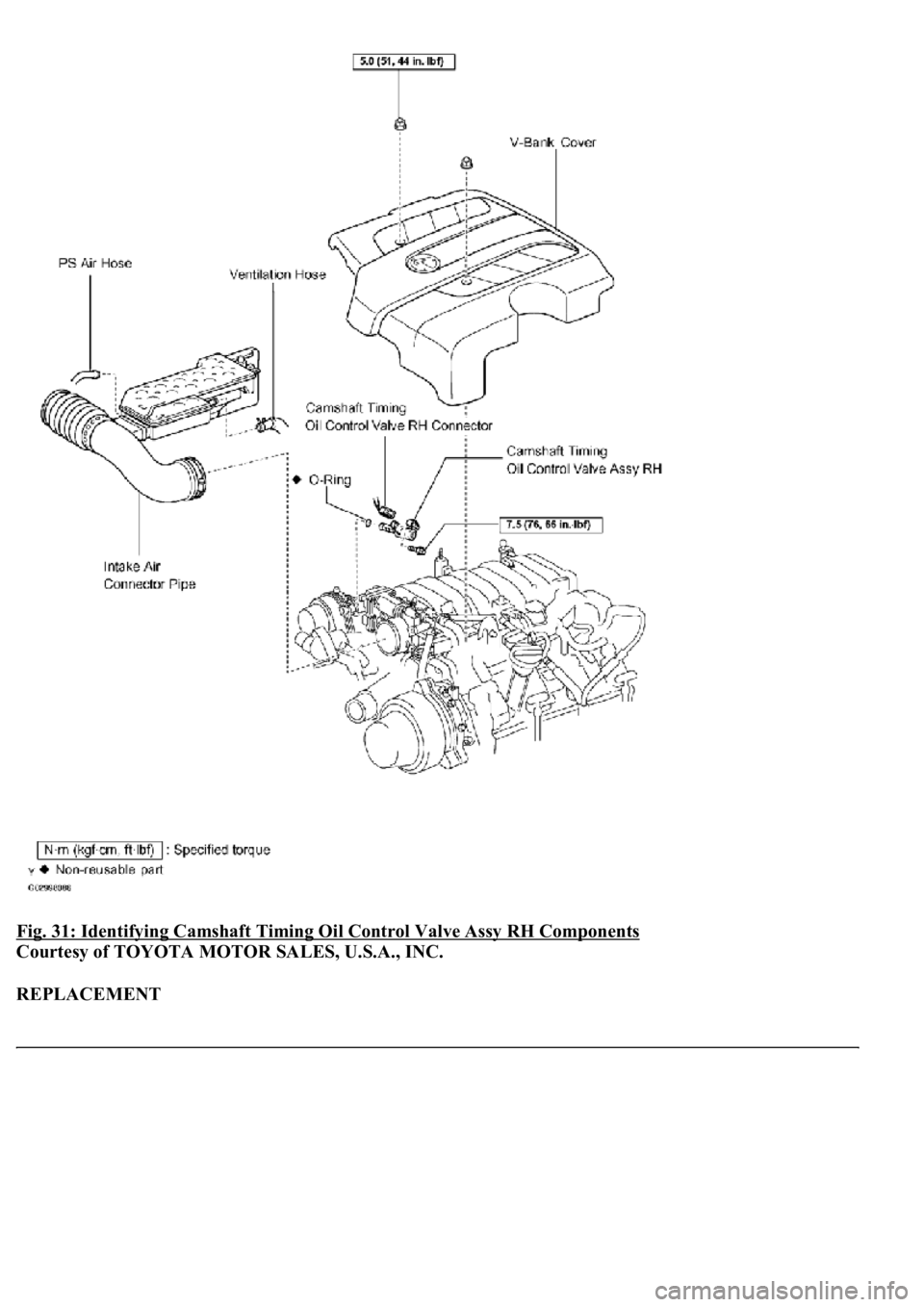
COMPONENTS
Page 2973 of 4500
Fig. 31: Identifying Camshaft Timing Oil Control Valve Assy RH Components
Courtesy of TOYOTA MOTOR SALES, U.S.A., INC.
REPLACEMENT
Page 2974 of 4500
1.REMOVE V-BANK COVER
a. Remove the 2 nuts and V-bank cover.
2.REMOVE AIR CLEANER INLET NO.1
3.REMOVE INTAKE AIR CONNECTOR PIPE
a. Disconnect the air hose and ventilation hose.
b. Remove the bolt.
c. Loosen the 2 hose clamps and remove the intake air connector pipe.
4.REMOVE CAMSHAFT TIMING OIL CONTROL VALVE ASSY RH
a. Disconnect the oil control valve connector.
b. Remove the bolts and oil control valve.
5.INSTALL CAMSHAFT TIMING OIL CONTROL VALVE ASSY RH
a. Install the oil control valve with the bolt.
Torque: 7.5 N.m (76 kgf.cm, 66 in..lbf)
b. Connect the oil control valve connector.
6.INSTALL INTAKE AIR CONNECTOR PIPE
a. Install the intake air connector pipe with the bolt and 2 hose clamps.
Torque:
4.0 N.m (41 kgf.cm, 35 in..lbf) for hose clamp
5.0 N.m (51 kgf.cm, 44 in..lbf) for bolt
7.INSTALL AIR CLEANER INLET NO.1
8.INSTALL V-BANK COVER
Torque: 5.0 N.m (51 kgf.cm, 44 in..lbf)
COMPONENTS
Page 2975 of 4500
Fig. 32: Identifying Camshaft Timing Oil Control Valve Assy LH Components
Courtesy of TOYOTA MOTOR SALES, U.S.A., INC.
REPLACEMENT
Page 2976 of 4500
1.REMOVE V-BANK COVER
a. Remove the 2 nuts and V-bank cover.
2.REMOVE CAMSHAFT TIMING OIL CONTROL VALVE ASSY LH
a. Disconnect the oil control valve connector.
b. Remove the bolts and oil control valve.
3.INSTALL CAMSHAFT TIMING OIL CONTROL VALVE ASSY LH
a. Install the oil control valve with the bolt.
Torque: 7.5 N.m (76 kgf.cm, 66 in..lbf)
b. Connect the oil control valve connector.
4.INSTALL V-BANK COVER
Torque: 5.0 N.m (51 kgf.cm, 44 in..lbf)
COMPONENTS
Page 2977 of 4500
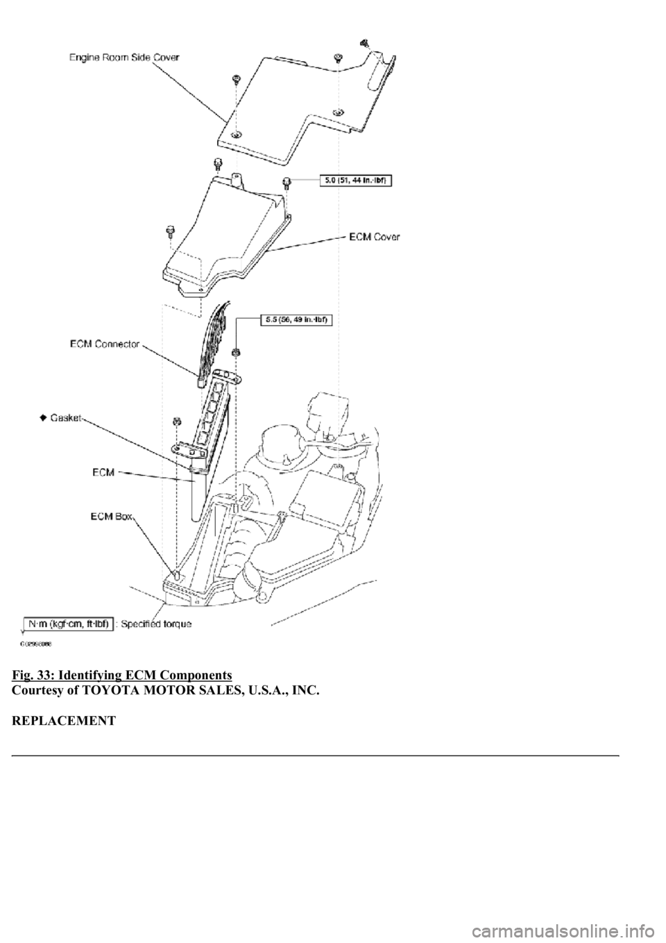
Fig. 33: Identifying ECM Components
Courtesy of TOYOTA MOTOR SALES, U.S.A., INC.
REPLACEMENT
Page 2978 of 4500
1.DISCONNECT BATTERY NEGATIVE TERMINAL
2.REMOVE ENGINE ROOM SIDE COVER
a. Remove the 3 clips and engine room side cover.
3.REMOVE ECM COVER
a. Remove the 3 bolts and ECM cover.
4.REMOVE ECM
a. Remove the 2 nuts.
b. Disconnect the connector and remove the ECM.
5.REMOVE ECM GASKET
Page 2979 of 4500
Fig. 34: Removing ECM Gasket
Courtesy of TOYOTA MOTOR SALES, U.S.A., INC.
a. Peel off the sponge part of the gasket.
b.Spray gasket remover or equivalent on the remaining tape of the gasket.
Page 2980 of 4500
Fig. 35: Spraying Gasket
Courtesy of TOYOTA MOTOR SALES, U.S.A., INC.
c. Use a cutter knife. to remove the tape of the gasket.
Trending: Manifold gasket, fuse, wipers, steering, wheel alignment, intake manifold inlet, fuel pump
