LEXUS LS430 2003 Factory Repair Manual
Manufacturer: LEXUS, Model Year: 2003,
Model line: LS430,
Model: LEXUS LS430 2003
Pages: 4500, PDF Size: 87.45 MB
LEXUS LS430 2003 Factory Repair Manual
LS430 2003
LEXUS
LEXUS
https://www.carmanualsonline.info/img/36/57050/w960_57050-0.png
LEXUS LS430 2003 Factory Repair Manual
Trending: seats, driver seat adjustment, damper, tail light replacement, airbag off, boot, height adjustment
Page 2981 of 4500
Fig. 36: Removing Taping Gasket Using Cutter
Courtesy of TOYOTA MOTOR SALES, U.S.A., INC.
6.INSTALL ECM GASKET
a. Clean the ECM's seal surface to the gasket with non-reside solvent.
b. Attach the gasket on the ECM.
7.INSTALL ECM
a. Connect the connector and install the ECM with the 2 nuts.
Page 2982 of 4500
Torque: 5.5 N.m (55 kgf.cm, 48 in..lbf)
8.INSTALL ECM COVER
a. Install the ECM cover with the 3 bolts.
Torque: 5.0 N.m (51 kgf.cm, 44 in..lbf)
9.INSTALL ENGINE ROOM SIDE COVER
a. Install the engine room side cover with the 3 clips.
10.CONNECT BATTERY NEGATIVE TERMINAL
11.CONFIGURE ECM FOR OPTIONAL DYNAMIC RADAR/LASER CRUISE CONTROL
a. Be sure to perform the following procedures after replacing the ECM.
1. Turn the ignition switch ON.
2. Turn the cruise main switch ON.
3. With the brake pedal depressed, set the cruise control main switch to RES/ACC 3 times within 3
seconds. Check that the VSC buzzer sounds at this time.
4. Turn the ignition switch OFF.
5. Connect the intelligent tester II to the DLC3.
6. Turn the ignition switch ON and push the intelligent tester II main switch ON.
7. Select the item "L/C Option Flag" in the Data List.
8. Check that YES is displayed.
12.POWER WINDOW CONTROL SYSTEM INITIALIZE (See INITIALIZATION
)
13.FRONT POWER SEAT CONTROL SYSTEM INITIALIZE (See INITIALIZATION
)
REPLACEMENT
1.REMOVE ACCELERATOR PEDAL ROD ASSY
Page 2983 of 4500
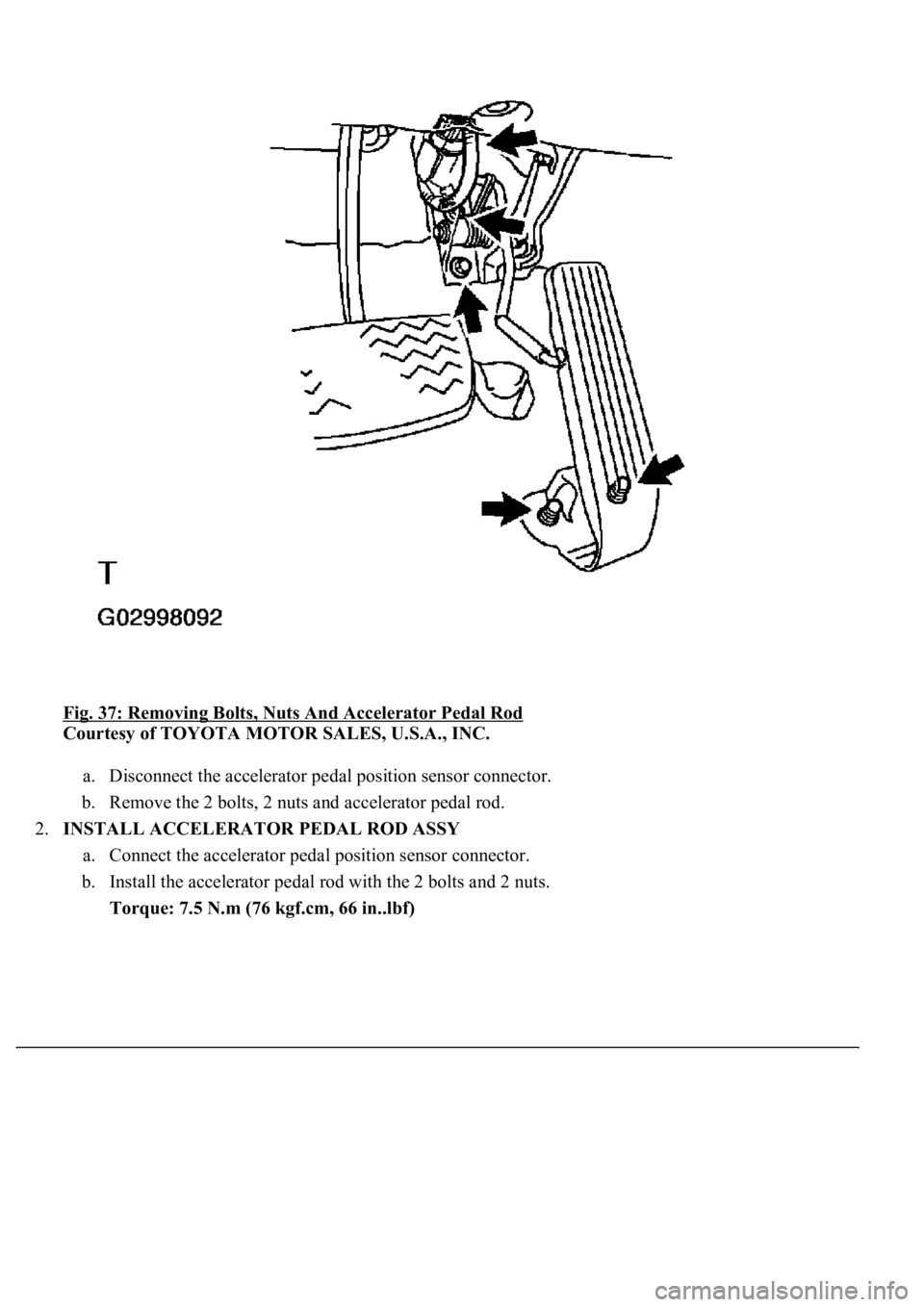
<0029004c004a001100030016001a001d000300350048005000520059004c0051004a000300250052004f00570056000f00030031005800570056000300240051004700030024004600460048004f0048005500440057005200550003003300480047004400
4f0003003500520047[
Courtesy of TOYOTA MOTOR SALES, U.S.A., INC.
a. Disconnect the accelerator pedal position sensor connector.
b. Remove the 2 bolts, 2 nuts and accelerator pedal rod.
2.INSTALL ACCELERATOR PEDAL ROD ASSY
a. Connect the accelerator pedal position sensor connector.
b. Install the accelerator pedal rod with the 2 bolts and 2 nuts.
Torque: 7.5 N.m (76 kgf.cm, 66 in..lbf)
Page 2984 of 4500
Page 2985 of 4500
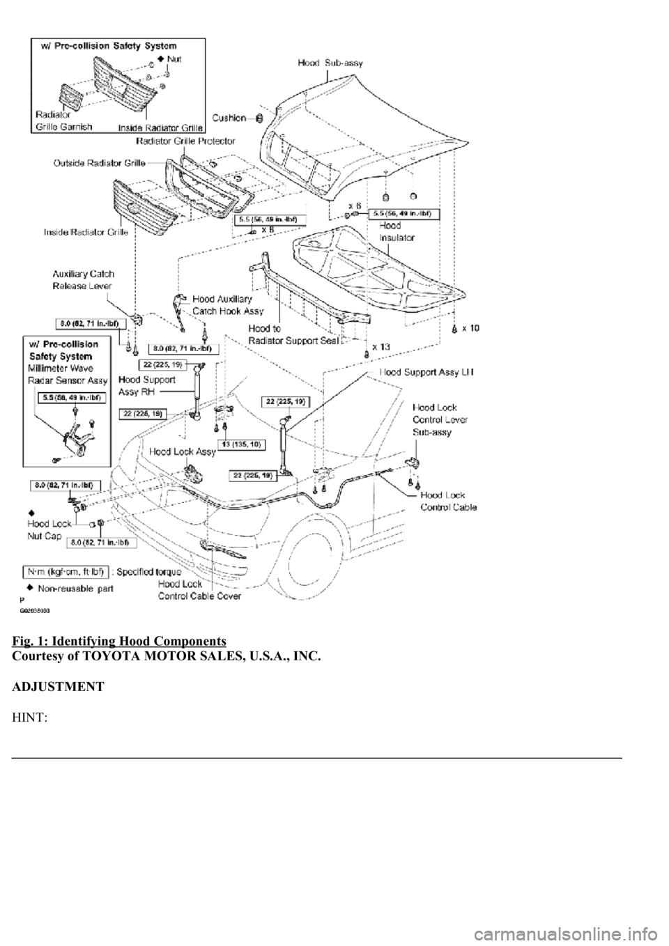
Fig. 1: Identifying Hood Components
Courtesy of TOYOTA MOTOR SALES, U.S.A., INC.
ADJUSTMENT
HINT:
Page 2986 of 4500
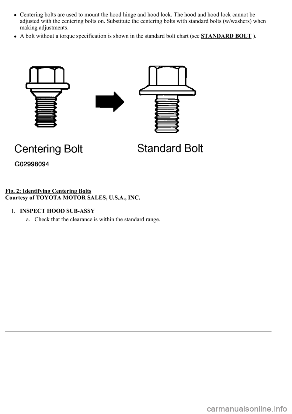
Centering bolts are used to mount the hood hinge and hood lock. The hood and hood lock cannot be
adjusted with the centering bolts on. Substitute the centering bolts with standard bolts (w/washers) when
making adjustments.
A bolt without a torque specification is shown in the standard bolt chart (see STANDARD BOLT ).
Fig. 2: Identifying Centering Bolts
Courtesy of TOYOTA MOTOR SALES, U.S.A., INC.
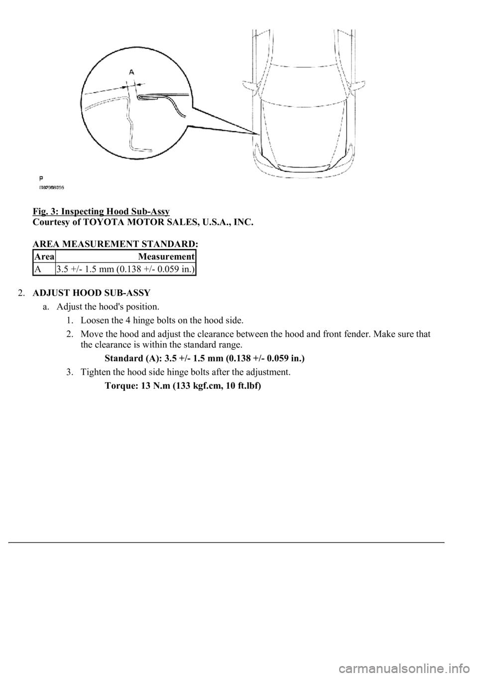
1.INSPECT HOOD SUB-ASSY
a. Check that the clearance is within the standard range.
Page 2987 of 4500
Fig. 3: Inspecting Hood Sub-Assy
Courtesy of TOYOTA MOTOR SALES, U.S.A., INC.
AREA MEASUREMENT STANDARD:
2.ADJUST HOOD SUB-ASSY
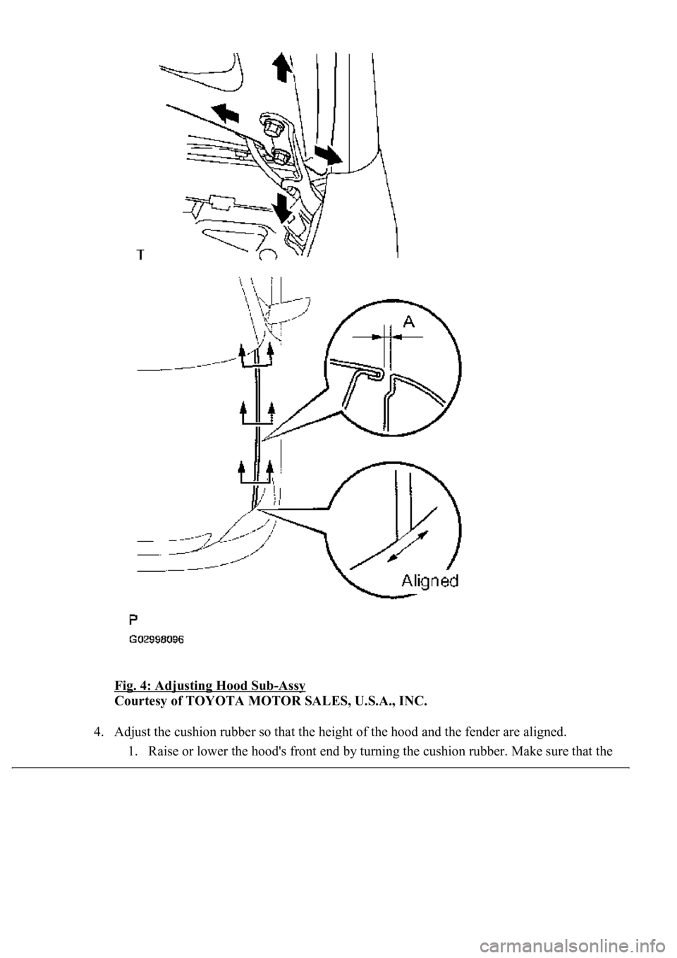
a. Adjust the hood's position.
1. Loosen the 4 hinge bolts on the hood side.
2. Move the hood and adjust the clearance between the hood and front fender. Make sure that
the clearance is within the standard range.
Standard (A): 3.5 +/- 1.5 mm (0.138 +/- 0.059 in.)
3. Tighten the hood side hinge bolts after the adjustment.
Torque: 13 N.m (133 kgf.cm, 10 ft.lbf)
AreaMeasurement
A3.5 +/- 1.5 mm (0.138 +/- 0.059 in.)
Page 2988 of 4500
Fig. 4: Adjusting Hood Sub-Assy
Courtesy of TOYOTA MOTOR SALES, U.S.A., INC.
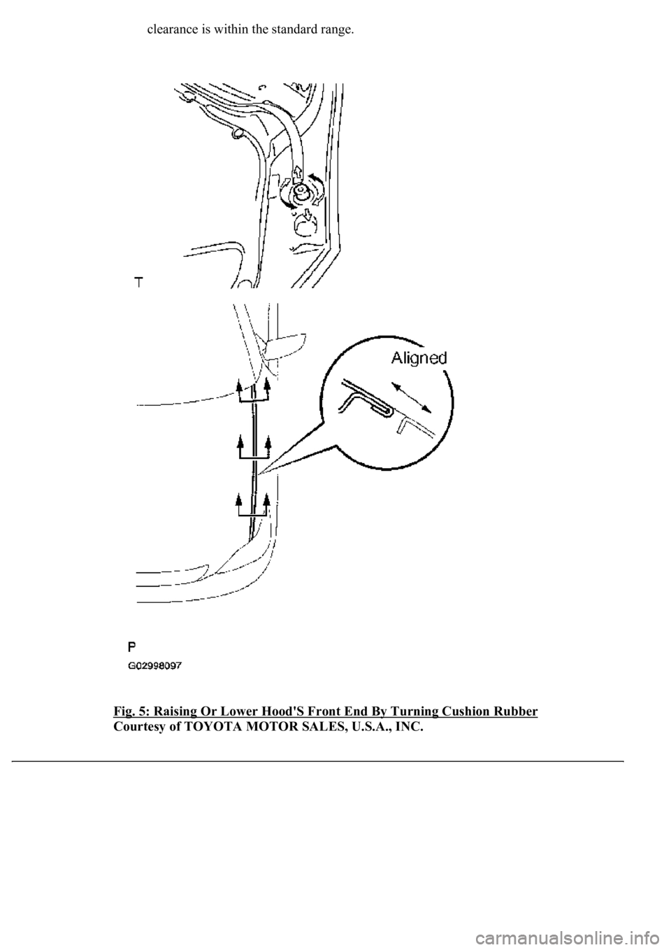
4. Adjust the cushion rubber so that the height of the hood and the fender are aligned.
1. Raise or lower the hood's front end b
y turning the cushion rubber. Make sure that the
Page 2989 of 4500
clearance is within the standard range.
Fig. 5: Raising Or Lower Hood'S Front End By Turning Cushion Rubber
Courtesy of TOYOTA MOTOR SALES, U.S.A., INC.
Page 2990 of 4500
5. Adjust the hood lock.
1. w/ Pre-collision safety system:
Disconnect the cable from the battery negative (-) terminal.
2. w/ Pre-collision safety system:
Disconnect the connector.
3. w/ Pre-collision safety system:
Remove the 3 bolts and millimeter wave radar sensor.
Fig. 6: Removing Bolts And Millimeter Wave Radar Sensor
Courtesy of TOYOTA MOTOR SALES, U.S.A., INC.
4. Remove the cap (see OVERHAUL
).
5. Loosen the 2 bolts and nut.
6. Ad
just the hood lock position so that the striker can enter it smoothly.
Trending: Absorber suspension, airbag, mirror, fuses, transmission fluid, head, spark plugs
